Aluminum T Bracket Engineering for Solid Aluminium Rainscreen Cladding Systems
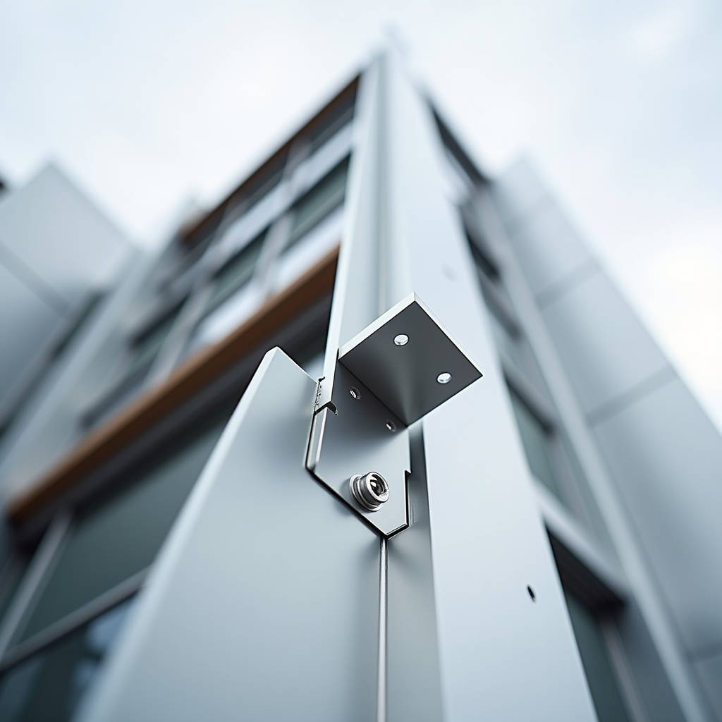
In the world of rainscreen cladding and curtain wall engineering, the conversation typically revolves around panel flatness, PVDF coating integrity, and wind load performance. But every facade engineer who has spent time on a scaffold knows that the difference between a straight sightline and a call-back nightmare often comes down to a single piece of hardware: the Aluminum T Bracket. This component, a deceptively simple L-shaped or T-shaped connector fabricated from solid aluminium, serves as the primary load-transfer point between the cladding panel and the building's structural substrate. When a 3.0mm solid aluminium panel weighing upwards of 18 kilograms per square meter catches a 2.0 kPa wind gust, the entire tensile and shear load channels through these brackets. Getting the alloy selection, anodizing thickness, and slot geometry right is not a matter of hardware catalog shopping. It is a matter of structural due diligence that separates a 30-year facade from one that develops stress cracks within five.
Why the Aluminum T Bracket Is Not Just Another Extrusion
Walk through any industrial supply catalog and you will find thousands of T-slot brackets, gussets, and joining plates. The McMaster-Carr and TSLOTS ecosystems have built entire framing industries around modular aluminium extrusions. But a bracket designed for a machine guard or a workstation frame operates under a fundamentally different set of constraints than one buried inside a ventilated rainscreen on a 40-story tower. The Aluminum T Bracket used in solid aluminium cladding applications must handle cyclic thermal expansion, continuous dead load, intermittent wind suction, and decades of moisture exposure without galvanic corrosion at the fastener interface.
Three engineering distinctions separate a cladding-grade bracket from a general-purpose T-slot connector:
- Alloy grade specificity. Industrial framing brackets are often extruded from 6105-T5 or 6063-T6, which offer good extrudability but moderate strength. Cladding brackets, particularly those specified for high-wind zones or heavy 3.0mm solid panels, should be machined or extruded from 6061-T6, which delivers a minimum tensile strength of 290 MPa versus 6063-T6 at roughly 240 MPa. That 50 MPa difference becomes significant when you calculate the bending moment at the bracket's heel under negative wind pressure.
- Coating compatibility. A bracket hidden behind a PVDF-coated panel still needs corrosion protection. Mill-finish aluminium in contact with stainless steel fasteners and alkaline cementitious substrates will develop pitting corrosion within the first wet-dry cycle. The bracket requires either a minimum 15-micron anodized layer (AA-M12C22A31 per AAMA 611) or a chromate conversion coating prior to installation.
- Slot tolerance and thermal movement accommodation. Unlike a rigid machine frame, a cladding bracket must permit differential movement. A 3-meter solid aluminium panel will expand approximately 2.0mm across a 50°C temperature swing. The bracket's slotted hole geometry must absorb this movement without transferring stress into the panel or the fastener.
Load Path Analysis: What Happens When Wind Hits a Solid Aluminium Panel
Understanding the Aluminum T Bracket requires tracing the load path from the panel face to the building structure. A solid 2.5mm aluminium panel spanning 1,200mm between vertical supports, subjected to a design wind pressure of 1.8 kPa (typical for a mid-rise building in a suburban exposure category), generates a uniformly distributed load that resolves into point loads at each bracket location.
The calculation is straightforward but often overlooked during procurement. For a panel measuring 1.2m wide by 3.0m tall, the tributary area per bracket (assuming four brackets per panel, two per vertical rail) is roughly 0.9 square meters. At 1.8 kPa, each bracket sees a service load of approximately 1.62 kN in tension or compression, depending on wind direction. Add a safety factor of 2.0 for cladding components per ASCE 7-22 Chapter 30, and the bracket must sustain 3.24 kN without yielding.
This is where the 6061-T6 requirement becomes non-negotiable. A bracket fabricated from 6063-T5 might hold under static load but will creep under sustained tension. Creep in aluminium alloys becomes measurable above 100°C in most grades, but in the context of a facade, the concern is not thermal creep. It is the micro-yielding that accumulates over thousands of wind cycles. The fatigue limit for 6061-T6 at 5×10⁸ cycles is approximately 96 MPa. For 6063-T5, it drops to roughly 70 MPa. A bracket designed too close to the yield margin in 6063-T5 will eventually develop a crack at the inside corner radius, where stress concentration factors peak.
Geometry and Fabrication: Cast, Extruded, or Machined from Plate
The Aluminum T Bracket in cladding applications comes from three distinct manufacturing routes, each with implications for cost, lead time, and structural reliability.
Extruded brackets dominate the T-slot framing world. The die cost for a custom extrusion profile runs between $1,500 and $3,000, with a minimum order quantity typically starting at 500 kilograms. For a project requiring 2,000 identical brackets, extrusion offers the lowest per-unit cost. But the extrusion process limits the alloy selection. 6061 extrudes poorly compared to 6063, so many extruders will push the customer toward 6063-T6, which hits the tensile number but lacks the fatigue performance of 6061-T6.
Machined-from-plate brackets start with a 6061-T6 plate, typically 6mm to 10mm thick, laser-cut or waterjet-cut to the T-shape profile, then drilled and tapped. This route eliminates the die cost and allows precise control over the inside corner radius, a critical detail for fatigue resistance. A sharp internal corner acts as a stress riser. A radius of at least 3mm, or 0.5 times the material thickness, whichever is greater, reduces the stress concentration factor significantly. Machined brackets cost more per unit than extruded ones but make sense for projects under 500 units or when the engineering specification demands 6061-T6 with documented mill test reports.
Cast brackets appear in some architectural hardware catalogs, often in zinc-aluminium alloys or A356 aluminium. Casting allows complex geometries but introduces porosity. A cast bracket with 2% internal porosity can lose 10-15% of its tensile capacity. For a rainscreen application where the bracket is hidden and inaccessible for 30 years, the risk of a casting defect propagating into a fatigue crack argues against cast components unless each bracket undergoes X-ray inspection, which erases the cost advantage.
Futeng® has supplied machined 6061-T6 T brackets for multiple high-rise cladding projects in Southeast Asia and the Middle East, where the combination of coastal salt spray and typhoon-level wind loads made the fatigue argument decisive. The brackets were specified with a 20-micron anodized finish and 316 stainless steel fasteners with nylon isolating washers to prevent galvanic coupling.
Galvanic Corrosion: The Hidden Degradation Mechanism
Every Aluminum T Bracket in a facade assembly sits at the intersection of at least two, and often three, dissimilar metals. The bracket itself is aluminium. The fastener is typically stainless steel. The panel may be attached with a steel rivet or a stainless bolt. The substrate rail could be galvanized steel or aluminium. In the presence of an electrolyte (rainwater, condensation, or even high humidity in coastal environments), this assembly becomes a galvanic cell.
The galvanic series in seawater places aluminium at approximately -0.75V, while 304 stainless steel sits at about -0.05V. The potential difference of 0.70V is more than enough to drive corrosion of the aluminium, which acts as the anode. The rate of material loss depends on the surface area ratio. A large aluminium bracket connected to a small stainless steel fastener experiences relatively slow corrosion because the anodic current density is low. But a small aluminium bracket connected to a large galvanized steel substrate rail will corrode rapidly.
Three mitigation strategies apply:
- Isolation. Nylon or EPDM washers and bushings between the bracket and the substrate, and between the bracket and the fastener, break the electrical circuit. This is mandatory when the substrate is galvanized steel.
- Coating. Anodizing the bracket to at least AA15 (15 microns) creates a dielectric barrier. Note that anodizing is not a perfect insulator; it is porous at the microscopic level. A hot-water seal or a PTFE-infused seal improves the dielectric performance.
- Material selection. Where possible, use 6061-T6 aluminium for the substrate rail as well, eliminating the galvanic couple entirely. When steel must be used, specify hot-dip galvanizing to ISO 1461 rather than electroplated zinc, which is too thin for long-term facade service.
Thermal Bridging and Condensation Risk
A Aluminum T Bracket that connects a cold external cladding panel to a warm internal substrate creates a thermal bridge. Aluminium's thermal conductivity of approximately 160 W/m·K means that a bracket with a cross-sectional area of 200mm² and a length of 80mm will conduct heat at a rate that can drop the interior surface temperature at the fastener location below the dew point in cold climates.
The consequence is not just energy loss. Condensation at the bracket-to-substrate interface leads to corrosion, freeze-thaw damage in masonry substrates, and mold growth inside the cavity. The solution is a thermal break pad, typically a 5mm to 10mm thick pad of PVC, nylon, or a proprietary glass-fiber-reinforced thermoset, placed between the bracket and the substrate. The pad reduces the thermal transmittance of the connection by a factor of 10 to 20, depending on material and thickness.
For projects in ASHRAE climate zones 5 and above, the thermal break is not optional. It should be specified in the bracket submittal package along with the U-value calculation for the point thermal bridge, calculated per ISO 10211 or ASHRAE Standard 90.1 Appendix A.
Slot Geometry and Adjustability: Getting the Panel Line Right
On paper, the facade is perfectly flat. On site, the concrete slab edges deviate by ±15mm from the design plane. The Aluminum T Bracket must provide enough adjustability in three axes to absorb substrate tolerances while delivering a panel plane flat to within 3mm over any 3-meter straightedge, per AAMA 609.1 and CWCT standards.
The three-axis adjustment system works as follows:
- Vertical adjustment (Z-axis). A slotted hole in the bracket's vertical leg, typically 30mm to 50mm long, allows the bracket to slide up or down on the substrate rail before tightening. This accommodates floor-to-floor height variations.
- Horizontal adjustment (X-axis, in-out). A threaded rod or a serrated interface between the bracket and the panel carrier allows the panel plane to be adjusted outward or inward. The serration pitch, typically 2mm to 3mm, sets the adjustment resolution.
- Lateral adjustment (Y-axis, left-right). A horizontal slot in the bracket's foot, or a sliding connection between the bracket and the panel rail, allows the panel to shift left or right to align with adjacent panels.
The slot dimensions must be engineered for the fastener size. An M8 bolt in a 9mm-wide slot provides 1mm of clearance, which is adequate for adjustment but tight enough to prevent slip under load. The slot length should be at least 3 times the bolt diameter to provide meaningful adjustment range. A 30mm slot for an M8 bolt is a common specification.
One failure mode that field engineers encounter: the serrated washer under the bolt head strips the anodized coating off the bracket face during adjustment, creating a corrosion initiation site. A stainless steel flat washer between the serrated washer and the bracket face distributes the contact pressure and preserves the coating.
Comparative Analysis: Bracket Types for Solid Aluminium Cladding
The table below provides a practical comparison of the three primary bracket types encountered in solid aluminium rainscreen specifications. The data reflects typical values for a bracket supporting a 2.5mm to 3.0mm solid panel in a mid-rise application.
| Parameter | Extruded 6063-T6 | Machined 6061-T6 Plate | Cast A356-T6 |
|---|---|---|---|
| Tensile Strength (MPa) | 240 | 290 | 230 |
| Fatigue Limit at 5×10⁸ Cycles (MPa) | ~70 | ~96 | ~60 |
| Corrosion Resistance (Uncoated, 1,000hr Salt Spray) | Moderate pitting | Moderate pitting | Severe pitting (porosity) |
| Tooling Cost (USD) | $1,500–$3,000 (die) | $0 (nesting-based) | $2,000–$5,000 (mold) |
| Unit Cost at 500 pcs (USD) | $3.50–$5.00 | $6.00–$9.00 | $4.00–$6.00 |
| Unit Cost at 5,000 pcs (USD) | $1.80–$2.50 | $4.50–$6.50 | $2.50–$3.50 |
| Internal Corner Radius Control | Die-dependent (≥1.5mm) | CNC-controlled (≥3mm recommended) | Mold-dependent (≥2mm) |
| Thermal Break Compatibility | Good | Excellent | Limited |
| Lead Time (Custom Spec) | 6–8 weeks | 2–3 weeks | 8–10 weeks |
The numbers tell a clear story. For low-volume, high-performance applications, machined 6061-T6 brackets justify their cost premium through superior fatigue performance, faster lead times, and the elimination of die investment. For high-volume standardized systems, extruded brackets become economical once the die cost is amortized. Cast brackets occupy a middle ground that rarely makes engineering sense for exterior cladding unless the geometry is too complex to machine or extrude.
Specification Language: What to Write in the Submittal
A properly specified Aluminum T Bracket for solid aluminium cladding should reference the following minimum requirements in the project specification or procurement document:
"Aluminium T brackets shall be fabricated from 6061-T6 aluminium alloy per ASTM B209 for plate or ASTM B221 for extruded shapes. Minimum material thickness shall be 6mm for brackets supporting panels up to 2.5mm thickness and 8mm for panels 3.0mm and above. All brackets shall receive a chromate conversion coating per MIL-DTL-5541 Type I Class 3, or an anodized finish per AAMA 611 Class I (AA-M12C22A31, 15 microns minimum). Fasteners shall be 316 stainless steel with nylon isolating washers at all aluminium-to-steel interfaces. Slot dimensions shall provide a minimum of ±15mm vertical adjustment and ±20mm horizontal adjustment. Brackets shall be designed for a service load of [insert project-specific value] with a safety factor of 2.0 per ASCE 7-22. Manufacturer shall submit mill test reports for each heat of aluminium and coating thickness certificates for each batch."
This language, or a close variant, gives the contractor a clear compliance path and gives the engineer a defensible basis for approval. Vague specifications that call for "aluminium brackets" without alloy, thickness, or coating requirements invite substitution with low-cost 6063-T5 extrusions that may meet the letter of the spec but not the intent.
Installation Sequence and Quality Control
Even the best-engineered Aluminum T Bracket performs poorly if installed incorrectly. The installation sequence for a typical rainscreen bracket system follows a logical order:
- Substrate survey. Laser scan or total-station survey the substrate to map deviations from the design plane. This data informs the bracket shim schedule.
- Bracket layout. Mark bracket locations on the substrate per the approved shop drawings. Tolerance for bracket position: ±3mm horizontally, ±5mm vertically.
- Thermal break installation. Place thermal break pads between the bracket and the substrate. Do not compress the pad beyond 50% of its original thickness, as this reduces its thermal performance.
- Bracket fixing. Install the bracket with the specified fastener. Torque to the manufacturer's value. Under-torquing leads to slip; over-torquing strips threads or crushes the thermal break.
- Plane alignment. Using a laser plane or string lines, adjust each bracket's in-out position. Lock the adjustment mechanism. Verify the plane with a 3-meter straightedge.
- Panel hanging. Hang the panel onto the brackets. Verify the joint gap (typically 10mm to 20mm for a rainscreen) and panel alignment.
- Final inspection. Check panel flatness, joint width consistency, and fastener torque on a random sample of 10% of brackets.
One common field error deserves attention: installers sometimes omit the nylon isolating washer between the stainless steel fastener and the aluminium bracket, either because it is fiddly to position or because they believe the anodized coating provides sufficient isolation. It does not, particularly after the fastener threads cut through the anodized layer during installation. The washer is the last line of defense against galvanic corrosion, and its omission should be treated as a non-conformance in the inspection report.
Supply Chain Considerations for International Projects
For a general contractor or facade subcontractor sourcing Aluminum T Bracket components for a project in the Middle East, Southeast Asia, or North America, the supply chain decision involves more than unit price. Lead time, documentation quality, and compliance with local standards drive the total procurement cost.
Chinese manufacturers, including Futeng®, have invested heavily in CNC machining centers and anodizing lines that can produce 6061-T6 brackets to ASTM and AAMA standards. The lead time advantage is real: a machined bracket order of 5,000 pieces can ship in 3-4 weeks from a Chinese factory versus 6-8 weeks from many Western suppliers. But the contractor must verify that the mill test reports are genuine and traceable to the heat number. Third-party inspection by a firm like SGS or Bureau Veritas, at a cost of roughly $1,500 to $2,500 per inspection visit, provides assurance that the material in the box matches the paperwork.
For projects in the European Union, the brackets must carry CE marking under EN 1090-1 if they are considered structural components. This requires factory production control certification and, for brackets in Execution Class 2 and above, welding procedure qualification if any welding is involved in the bracket assembly. The contractor should clarify during the tender phase whether the brackets fall under EN 1090 scope, as this affects both supplier qualification and cost.
Fatigue Life and Long-Term Durability
Facade components are subject to wind-induced vibration that accumulates millions of cycles over a 30-year service life. The Aluminum T Bracket experiences fluctuating stress at the heel, where the vertical leg meets the horizontal foot. The stress range, not the peak stress, drives fatigue damage.
Miner's rule provides a framework for estimating cumulative fatigue damage. If the bracket experiences 10,000 cycles per year at a stress range of 50 MPa, and the S-N curve for 6061-T6 indicates a fatigue life of 2×10⁶ cycles at that stress range, the bracket consumes 0.5% of its fatigue life per year. Over 30 years, it consumes 15%, leaving a comfortable margin. But if the same bracket is fabricated from 6063-T5 with a sharp internal corner radius, the stress concentration factor can double the local stress range, and the lower fatigue limit of the alloy reduces the cycles to failure. What looked like a cost-saving substitution becomes a latent defect that manifests as a crack in year 15.
The engineering community has access to extensive fatigue data for aluminium alloys through sources like the Aluminum Association's Aluminum Design Manual and the European standard EN 1999-1-3 (Eurocode 9: Design of Aluminium Structures, Fatigue). Specifying brackets with reference to these standards shifts the conversation from "it looks strong enough" to "it has a documented fatigue life."
Making the Right Engineering Decision
The Aluminum T Bracket is a component that rewards attention to detail. The alloy choice, the fabrication method, the coating specification, the thermal break detail, and the installation quality control all contribute to a facade system that performs predictably for decades. The cost difference between a properly specified 6061-T6 machined bracket and a generic 6063-T5 extrusion is perhaps $3 to $5 per bracket. On a project with 10,000 brackets, that is $30,000 to $50,000, a fraction of one percent of the total facade package. The cost of a bracket failure, in terms of access, replacement, and reputational damage, is orders of magnitude higher.
For the facade engineer writing the specification, the recommendation is straightforward: specify the alloy, the coating, the fatigue performance, and the thermal break requirement explicitly. For the contractor sourcing the brackets, the recommendation is to audit the supplier's material certificates and coating quality, not just the unit price. For the installer, the recommendation is to treat every bracket as a structural connection, not a piece of hardware to be rushed into place. The panel that the public sees is only as secure as the bracket they never see.