Aluminum Transom Connector Engineering for Curtain Wall Load Path and Thermal Movement
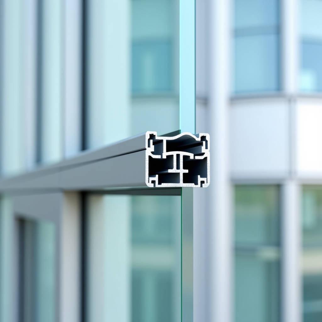
When a curtain wall contractor faces a transom-to-mullion connection that must handle 4.2 kPa wind loads while maintaining a 15 mm thermal movement tolerance, the Aluminum Transom Connector stops being a catalogue item and becomes a calculation point. The connector sits at the intersection of structural load path, water management, and thermal expansion — three systems that can work against each other if the connector design does not account for all of them simultaneously. This piece examines the engineering logic behind aluminum transom connections in stick-built curtain wall systems, specifically how connector geometry, alloy selection, and installation sequencing affect long-term facade performance. The focus is on solid aluminum extruded connectors used with 2.0–3.0 mm solid aluminium cladding panels, not composite materials, and the discussion draws on field data from high-rise projects in Southeast Asia and the Middle East where thermal cycling and monsoon-driven water penetration test connector designs to their limits.
What an Aluminum Transom Connector Actually Does in a Unitized System
In stick-built curtain wall construction, the transom — the horizontal framing member — transfers dead load from glass or solid aluminium panels to the vertical mullions. The Aluminum Transom Connector is the mechanical link that makes this transfer possible. It is typically a T-shaped or L-shaped aluminum extrusion that slides into the mullion pocket and receives the transom end, secured by screws or shear pins. The connector handles three distinct forces: vertical shear from panel weight, bending moment from wind pressure on the transom span, and axial force from thermal expansion restraint.
A common misunderstanding on site is treating the connector as a simple bracket. It is not. The connector must allow controlled slip in the longitudinal direction while resisting rotation and vertical displacement. If the connector is over-tightened or undersized, the transom cannot expand freely, and the resulting thermal stress can buckle mullions or crack glass. If the connector is too loose, the transom rattles under wind gusts and the water seal at the transom-mullion joint fails. Getting this balance right starts with understanding the alloy and temper.
Alloy Selection: Why 6063-T6 Dominates Transom Connector Extrusions
Most Aluminum Transom Connector profiles in commercial facades are extruded from 6063-T6 or 6005A-T61. The choice is not arbitrary. 6063-T6 offers a yield strength of approximately 170 MPa with elongation around 8%, which provides enough ductility for the connector to absorb thermal movement without fracturing. 6005A-T61 pushes yield strength to 200 MPa but sacrifices some extrudability, making it harder to achieve tight tolerance on complex connector geometries with integrated drainage channels.
The critical parameter that facade engineers check is the shear capacity of the connector tongue — the portion that inserts into the mullion. For a typical connector with a 4 mm tongue thickness and 50 mm engagement length, the shear capacity in 6063-T6 runs around 8.2 kN, assuming a safety factor of 2.0 against ultimate. This is sufficient for transom spans up to 1,800 mm carrying 6 mm tempered glass plus 2.5 mm solid aluminium spandrel panels. Beyond 2,400 mm spans, the connector tongue thickness typically increases to 6 mm, or the design switches to a double-tongue configuration.
ASTM B221 governs dimensional tolerances for aluminum extruded bars and shapes, including transom connector profiles. Specifiers should reference ASTM B221-20 for straightness, twist, and cross-section tolerance requirements.
Load Path Analysis: Where Connectors Fail First
Forensic investigation of failed curtain wall connections reveals a pattern: the Aluminum Transom Connector rarely fails in the aluminum itself. The failure chain usually starts at the screw connection. When a transom experiences cyclic wind loading, the screw holes in the connector elongate over time. This is a fretting fatigue mechanism — micro-motion between the stainless steel screw and the aluminum connector wall gradually erodes the aluminum, increasing the hole diameter until the connection develops play.
Field measurements from a 42-storey tower in Kuala Lumpur showed that after five years of service, connector screw holes in windward transoms had elongated by an average of 0.3 mm. This was enough to cause visible transom sag of 2–4 mm at mid-span, which in turn opened the horizontal pressure-equalization gaps and allowed water ingress during monsoon rains. The fix required replacing connectors with a revised design that included stainless steel threaded inserts pressed into the aluminum body, eliminating direct aluminum-to-screw contact.
The lesson for specifiers: when reviewing connector submittals, check whether the screw connection uses a bearing sleeve or threaded insert. A bare aluminum hole with a self-tapping screw is acceptable for low-rise applications with design wind loads below 1.5 kPa. For anything above 2.0 kPa, a reinforced connection point is necessary.
Thermal Movement: The Hidden Design Driver
Aluminum expands at approximately 23.4 × 10⁻⁶ per °C. For a 3,000 mm transom in a Middle Eastern facade where the temperature swing between night and midday can reach 45°C, the thermal elongation is 3.16 mm. The Aluminum Transom Connector must accommodate this movement without binding and without compromising the air seal.
There are two common approaches. The first uses a slotted screw hole in the connector, allowing the transom to slide relative to the screw. The slot length is calculated as the expected thermal movement plus a 2 mm tolerance. The second approach uses a fixed screw at one end of the transom and a sliding connector at the other end, with the sliding connector incorporating a low-friction pad — typically PTFE or EPDM — between the connector and the mullion pocket.
The sliding connector approach is more expensive to fabricate but provides more reliable long-term performance. Data from accelerated thermal cycling tests conducted per AAMA 501.5 show that slotted-hole connectors develop 30–40% more resistance to sliding after 5,000 cycles compared to the PTFE pad design, due to aluminum oxide buildup in the slot. For projects in high-temperature-range climates, the PTFE pad design is recommended despite the cost premium.
Water Management Integration
The Aluminum Transom Connector sits directly in the path of any water that penetrates the facade face. In a properly designed pressure-equalized system, the connector should be located in the "dry zone" behind the pressure-equalization chamber. But in practice, driving rain can reach the connector during extreme weather events, and condensation can form on the connector surface in high-humidity climates.
Connector corrosion is rarely a problem with 6063-T6 aluminum, but galvanic corrosion between the aluminum connector and stainless steel screws is a real concern in coastal environments. The standard mitigation is to isolate the two metals with a nylon washer or to specify screws with a proprietary anti-seize coating. AAMA 2604-compliant PVDF coating on the connector — the same coating system used on Futeng® solid aluminium cladding panels — adds an additional barrier, though the coating thickness on connectors is typically 25–30 microns rather than the 35–40 microns used on exposed panel faces.
Some connector designs now incorporate an integrated drainage path — a small channel in the connector body that directs any water reaching the connector down into the mullion drainage system. This is a detail worth specifying for projects in monsoon regions or anywhere with annual rainfall exceeding 1,500 mm.
Comparative Analysis: Connector Types by Application
The table below summarizes the key performance characteristics of four common Aluminum Transom Connector configurations. The data is based on typical extruded 6063-T6 profiles with standard mill finish unless otherwise noted.
| Connector Type | Max Transom Span | Shear Capacity (kN) | Thermal Movement Accommodation | Typical Cost Index (per unit) | Best Application |
|---|---|---|---|---|---|
| Standard T-connector, slotted hole | 1,800 mm | 8.2 | ±2.5 mm via slot | 1.0 | Low to mid-rise, temperate climate |
| Double-tongue T-connector | 2,400 mm | 14.5 | ±3.0 mm via slot | 1.6 | High-rise, moderate wind loads |
| Sliding connector with PTFE pad | 2,400 mm | 8.2 | ±5.0 mm via sliding | 2.2 | High thermal range, desert climate |
| Integrated drainage connector, threaded insert | 2,100 mm | 10.1 | ±2.5 mm via slot | 1.8 | Coastal, monsoon, high humidity |
Cost indices are normalized to the standard T-connector. Actual pricing varies by region, order volume, and finish specification. The values above reflect typical Asian manufacturing costs for mill-finish 6063-T6 extrusions and should be used for preliminary budgeting only.
Installation Sequencing and Its Impact on Connector Performance
Even the best-designed Aluminum Transom Connector will underperform if installed in the wrong sequence. The correct order is: mullion erection and alignment, connector insertion into mullion pocket, transom placement onto connector, screw fastening to specified torque, and finally panel installation. The common site error is installing panels before fully tightening transom connections, which pre-loads the connector with panel weight before the screw takes the load.
Torque control on connector screws is another area where site practice often diverges from engineering intent. Over-torquing a stainless steel screw into an aluminum connector can strip the threads or, in a slotted-hole design, crush the slot walls and eliminate the thermal movement allowance. The recommended torque for M6 stainless steel screws into 6063-T6 aluminum with a threaded insert is 4.5–5.5 N·m. Without an insert, the maximum torque drops to 3.0–3.5 N·m. Quality assurance protocols should include torque checks on a random sample of connections per floor, with results documented against the approved shop drawing values.
Material Compatibility with Solid Aluminium Cladding Panels
When the transom supports solid aluminium cladding panels — typically 2.0 mm, 2.5 mm, or 3.0 mm thick sheets with PVDF or FEVE coating — the connector must be detailed to avoid direct contact between the panel edge and the connector body. This is not a corrosion concern; both are aluminum. The issue is differential thermal expansion between the panel and the framing system. A 2.5 mm solid aluminium panel can expand independently of the transom, and if the panel edge bears against the connector, the panel can buckle or the connector can be subjected to unanticipated lateral loads.
The standard detail maintains a 6–8 mm gap between the panel edge and the connector, filled with a silicone weather seal that accommodates differential movement. The sealant must be compatible with the panel's PVDF coating — neutral-cure silicone is standard, as acetoxy-cure formulations can attack certain coating systems over time. ASTM C920 Class 25 sealants are commonly specified for this application.
For projects using Futeng® solid aluminium panels with a 3.0 mm thickness and PVDF coating, the panel weight per square meter is approximately 8.1 kg. Over a 1,200 mm × 3,000 mm transom grid, the dead load per connector is roughly 14.6 kg, well within the capacity of any connector type listed in the table above. The controlling design factor is wind load, not dead load, for all but the largest panel configurations.
Quality Verification: What to Inspect on Site
A practical inspection checklist for the Aluminum Transom Connector should cover five points. First, verify the alloy and temper marking on the extrusion — 6063-T6 should be stamped or labeled on the packaging. Second, measure the tongue thickness with a caliper at three points along the engagement length; variation should not exceed ±0.15 mm. Third, check the slot length against the thermal movement calculation in the shop drawings. Fourth, confirm the presence of nylon isolation washers at all stainless steel screw connections. Fifth, for coated connectors, measure the PVDF coating thickness with a calibrated gauge; the minimum acceptable reading is 25 microns per AAMA 2604.
One often-overlooked check is the alignment of the connector within the mullion pocket. If the connector is not seated squarely, the transom will be misaligned, and the resulting eccentric loading can reduce the connector's effective shear capacity by up to 15%. A simple go/no-go gauge that matches the connector profile can speed up this inspection on large projects.
Supply Chain Considerations for International Projects
For contractors sourcing Aluminum Transom Connector profiles for projects outside their home market, three supply chain factors deserve attention. First, extrusion die lead times: a custom connector profile requires a new die, which typically takes 3–4 weeks to manufacture and trial. Rush orders can compress this to 2 weeks but at a 30–50% premium. Second, minimum order quantities: most extrusion mills set MOQs at 300–500 kg per profile, which translates to roughly 2,000–4,000 connector pieces depending on size. Third, finish consistency: if connectors are to be anodized or PVDF-coated to match the facade, the entire batch should be processed in one run to avoid color variation.
Shipping aluminum extrusions internationally requires attention to packaging. Connectors are small, high-value items that are easily damaged in transit if not properly secured. The industry standard is to pack connectors in corrugated plastic trays with individual compartments, stacked on pallets with edge protectors. Sea freight from Asian manufacturing hubs to Middle Eastern or European ports typically adds 4–6 weeks to the lead time, which must be factored into the construction schedule.
Code References and Standards Compliance
Specifying an Aluminum Transom Connector requires reference to several standards. The Aluminum Design Manual (ADM) published by the Aluminum Association provides the basis for allowable stress design of aluminum structural components. ASTM E283 and E331 govern air leakage and water penetration testing of curtain wall assemblies, respectively, and the connector is a critical element in both test protocols. AAMA 501.5 covers thermal cycling, and connectors in high-movement applications should be validated against this standard. For projects in seismic zones, AAMA 501.4 provides guidance on inter-story drift accommodation, which the connector-mullion interface must handle without disengagement.
European projects typically reference EN 1999-1-1 (Eurocode 9) for aluminum structural design, which uses a different partial safety factor approach than the ADM. The connector capacity values calculated under ADM and Eurocode 9 can differ by 5–10%, so specifiers working across jurisdictions should confirm which code governs and ensure the connector supplier's calculations match.
The Aluminum Transom Connector is a small component in the facade assembly, but its design and specification ripple through the entire curtain wall system. Getting the alloy, geometry, thermal accommodation, and installation sequence right prevents problems that are expensive to fix after glazing. For engineers and contractors, the time spent on connector submittal review pays back in reduced callbacks and a facade that performs as calculated through decades of thermal cycles and storm events.