Aluminum Mullion Splice Engineering Internal Sleeve Design Load Transfer and Thermal Slip Detailing
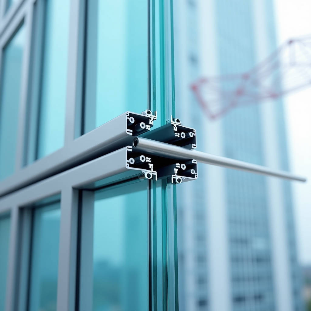
When a curtain wall spans multiple floors, the aluminum mullion cannot run as one continuous piece from foundation to roof. Material handling constraints, thermal expansion, and structural logic all demand breaks in the vertical extrusion. The Aluminum Mullion Splice is the engineered connection that bridges these breaks, transferring axial load, accommodating movement, and maintaining the visual alignment that architects specify. A poorly detailed splice introduces three problems at once: water ingress through misaligned joint gaps, stress concentration that cracks glass, and visible stepping at the facade plane that no amount of silicone can hide. This article focuses on the structural mechanics of internal sleeve splices, the most common approach in stick-built curtain wall systems, and examines how splice length, bolt configuration, and clearance tolerances interact with wind load, live load deflection, and thermal cycling. For project managers and facade engineers evaluating shop drawings, understanding what happens inside that hidden sleeve is the difference between a 30-year watertight facade and a warranty claim waiting to happen.
What Actually Happens Inside a Mullion Splice
The internal sleeve splice works on a deceptively simple principle: a smaller aluminum tube slides inside the hollow mullion extrusion, bridging the joint between upper and lower sections. The sleeve is bolted to one side — typically the lower mullion — while the upper mullion slides over the sleeve and rests on it without rigid fastening. This detail matters. The unfastened side allows the mullion to expand and contract along its length without transferring thermal strain into the anchor points. When the sun hits the south elevation at 2 p.m. in August, a 4.2-meter aluminum mullion can grow by roughly 2.5 mm. If both sides of the splice were bolted solid, that movement would find another path — usually through the glass or the anchor brackets.
The sleeve itself is typically fabricated from 6063-T6 or 6061-T6 aluminum, with wall thickness ranging from 3.0 mm to 6.0 mm depending on the mullion's moment of inertia and the design wind load. The critical dimension is the engagement length: how far the sleeve penetrates into each mullion segment. Engineering judgment and testing data from ASTM E330 (uniform load deflection) and AAMA 501.4 (interstory drift) have established that engagement length should be no less than 1.5 times the mullion depth for standard applications, and up to 2.0 times for high-wind zones or seismic categories D and above.
Load Transfer: Not Just Gravity
Many contractors assume the splice only carries the dead load of the mullion above. That assumption is wrong and dangerous. The splice must resist a combination of loads simultaneously:
- Axial compression from the self-weight of mullions, glass, and horizontal framing stacked above
- Bending moment induced by wind pressure and suction acting on the facade surface, which tries to rotate the splice joint open
- Shear from interstory drift during seismic events, where the floor slab moves laterally relative to the mullion axis
- Torsion in corner mullions where wind loads hit two adjacent faces at different pressure coefficients
In a typical 4.2-meter floor-to-floor span with a 1.5 kPa design wind pressure (approximately 145 mph wind speed per ASCE 7), the bending moment at mid-span can reach 3.3 kN·m for a mullion spaced at 1.5 meters on center. The splice, located at the point of lateral support (the floor slab anchor), sees near-zero bending moment — but this is only true if the anchor bracket is properly detailed. If the anchor allows rotation, the splice inherits moment that the sleeve was never designed to carry.
Sleeve Geometry and Bolt Configuration
The internal sleeve is not a generic rectangular tube. It must match the internal profile of the mullion extrusion, accounting for screw ports, thermal break pockets, and gasket raceways. A sleeve that is too loose rattles and allows the upper mullion to rotate under wind suction. A sleeve that is too tight binds during installation and prevents the thermal slip that the detail depends on. The industry standard clearance is 0.5 mm to 1.0 mm per side, achieved either by machining the sleeve from a solid billet or by specifying a custom extrusion with reduced external dimensions.
Bolt placement follows a consistent logic. The lower mullion receives two or four stainless steel bolts — typically M8 or M10 in metric projects, or 5/16-inch or 3/8-inch in imperial — passing through both the mullion wall and the sleeve. The bolts are positioned near the top of the lower mullion segment, leaving the majority of the sleeve projecting upward into the upper mullion. The upper mullion is not bolted through; instead, it receives a slotted hole or an oversized clearance hole that allows the bolt shank to pass without clamping the mullion wall. This detail is frequently missed in fabrication drawings, and the result is a locked splice that defeats the thermal expansion allowance.
Material Selection: Why 6063-T6 Dominates
Aluminum mullion splices are almost exclusively produced from 6063-T6 alloy. The T6 temper provides a minimum ultimate tensile strength of 215 MPa and yield strength of 170 MPa, which is sufficient for most curtain wall applications when combined with appropriate safety factors. For high-load conditions — mullions exceeding 200 mm in depth, spans over 5 meters, or wind pressures above 2.5 kPa — 6061-T6 may be specified for its higher yield strength of 240 MPa. The trade-off is extrudability: 6061 is harder to push through complex die profiles, which limits the sleeve geometry options and increases cost.
Corrosion protection is rarely a concern for the sleeve itself, since it sits inside the mullion cavity and is shielded from direct weather exposure. However, the stainless steel bolts that secure the sleeve create a galvanic couple with the aluminum. In coastal or industrial environments, the bolt holes should receive a wet-install sealant or an isolating bushing to prevent crevice corrosion. AAMA 2604 and 2605 coating standards do not apply to internal splice components, but the bolt specification should reference ASTM A193 (stainless steel bolting) or ISO 3506 for metric fasteners.
Thermal Performance and Condensation Risk
An aluminum sleeve bridging two mullion segments creates a continuous metal path through the joint. In a thermally broken curtain wall system, this represents a potential thermal bridge that can drop the interior surface temperature at the splice location below the dew point. The result is condensation on the interior mullion face during cold weather, which leads to occupant complaints and, over time, corrosion of steel anchor brackets and fastener heads inside the cavity.
The severity depends on the thermal break design. In a pour-and-debridge system, where the interior and exterior aluminum profiles are separated by a polyurethane thermal barrier, the splice sleeve typically sits entirely within the interior (warm-side) cavity. The thermal break is continuous across the splice joint, and the sleeve does not compromise the thermal performance. In a pressure-plate system without a true thermal break, the sleeve acts as a direct conductor between the cold exterior face and the warm interior face, and condensation is almost inevitable in climates where the January design temperature drops below -5°C.
The following table compares thermal performance outcomes for different splice configurations across climate zones:
| Splice Configuration | Climate Zone (ASHRAE) | Interior Surface Temp at Splice | Condensation Risk | Recommended Mitigation |
|---|---|---|---|---|
| Internal sleeve, thermally broken mullion | Zone 4-5 (Mixed/Cool) | 14.2°C at -10°C exterior | Low | None required |
| Internal sleeve, non-thermal mullion | Zone 4-5 (Mixed/Cool) | 8.7°C at -10°C exterior | Moderate | Interior gasket at splice joint |
| Internal sleeve, non-thermal mullion | Zone 6-7 (Cold/Very Cold) | 3.1°C at -25°C exterior | High | Insulated sleeve wrap + vapor barrier |
| External fishplate splice | Zone 6-7 (Cold/Very Cold) | -2.4°C at -25°C exterior | Severe | Not recommended for cold climates |
| Internal sleeve, triple-glazed, thermal mullion | Zone 8 (Subarctic) | 12.8°C at -35°C exterior | Low-Med | Supplemental cavity insulation |
Field Adjustment and Installation Realities
Shop drawings show the splice as a neat, orthogonal assembly. The construction site rarely cooperates. Floor slabs are poured with camber, anchor embeds are misplaced by 10 mm, and mullions arrive from the extruder with a slight bow from the cooling process. The splice must absorb these deviations without transmitting stress into the glass or the anchor system.
The US Patent 6,598,361 (Mullion splice joint design) describes a system where the splice connector allows field adjustability while limiting mullion and curtain wall deflections to tolerable levels. The key insight from this design is the open-gap joint: a deliberate separation between the upper and lower mullion ends that accommodates vertical adjustment and thermal movement. The gap is typically 10 mm to 15 mm, covered by a silicone-sealed exterior pressure plate or a snap-on cover that hides the joint from view while allowing water to drain to the exterior.
Installation sequence matters. The lower mullion is anchored to the floor slab first, with the splice sleeve pre-bolted and projecting upward. The upper mullion is lowered onto the sleeve from above. If the upper mullion binds on the sleeve, installers are tempted to hammer it down — an action that can gall the aluminum surfaces, create a permanent interference fit, and destroy the slip joint function. The correct approach is to verify sleeve straightness and mullion internal clearance before lifting, and to use a lubricant-free dry fit with a controlled insertion force.
Common Fabrication Errors
Based on field observations across dozens of projects, the following errors appear with troubling frequency in aluminum mullion splice fabrication:
- Undersized engagement length: Sleeves cut to 150 mm when the mullion depth demands 250 mm minimum. This happens when fabricators optimize material yield from standard 6-meter bar stock without checking the engineering requirements.
- Through-bolting both sides: The upper mullion is drilled and bolted solid to the sleeve, eliminating the thermal expansion joint. This error is often discovered during the first hot season when mullions bow outward between anchor points.
- Mismatched alloy: Sleeves fabricated from 6063-T5 instead of T6, reducing yield strength by approximately 25%. The T5 temper (cooled from extrusion and artificially aged) does not achieve the full strength of T6 (solution heat-treated and artificially aged).
- Missing drain slots: The sleeve blocks the internal drainage path of the mullion cavity. Without a weep hole drilled through the sleeve at the joint, water trapped in the upper mullion has no exit path and eventually finds its way into the building through fastener holes.
Designing for Seismic Drift
In seismic design categories D, E, and F, the curtain wall must accommodate interstory drift without losing structural integrity or glass retention. The mullion splice is a critical node in this performance chain. A rigid splice that cannot accommodate the relative displacement between floors will fracture at the bolt holes or tear the anchor bracket out of the slab edge.
The AAMA 501.4 test standard requires a dynamic racking test that simulates the design earthquake displacement. The splice must allow the upper and lower mullion segments to rotate relative to each other without binding, and the sleeve must remain engaged on both sides of the joint throughout the full drift cycle. This demands a longer engagement length than static design alone would suggest — typically 2.0 to 2.5 times the mullion depth for seismic applications, with a slotted bolt hole in the upper mullion that provides at least 15 mm of vertical travel.
For projects in high-seismic regions, some engineers specify an external fishplate splice instead of an internal sleeve. The fishplate — a flat aluminum plate bolted to the exterior face of both mullion segments — provides easier inspection and replacement after a seismic event. The trade-off is aesthetics: the fishplate is visible on the exterior unless concealed behind a projecting cover cap, and it creates a thermal bridge that is difficult to insulate. Internal sleeves remain the preferred solution for most architectural applications, with the seismic performance achieved through careful detailing of the bolt slotted holes and the sleeve engagement length.
Water Management at the Splice Joint
The splice joint is a discontinuity in the mullion's exterior face, and water driven by wind pressure will find it. The defense strategy follows the rainscreen principle: the outer seal stops most water, the internal drainage cavity collects and redirects what penetrates, and the air seal on the interior side prevents pressure equalization that would suck water inward.
At the splice, the exterior gasket or silicone seal must bridge the gap between upper and lower mullion segments. A continuous gasket is preferred over a butt joint, which opens under thermal contraction and creates a direct path for water entry. The internal drainage cavity must remain open across the splice — the sleeve should not block the vertical drainage path. A weep hole of 6 mm minimum diameter should be drilled through the sleeve at the low point of the joint, aligned with the exterior weep slots in the mullion face.
For projects specifying solid aluminum cladding panels integrated with the curtain wall, the panel joint layout should be coordinated with the mullion splice locations. A panel joint that aligns with a mullion splice creates a double discontinuity that is difficult to seal reliably. Offset the panel joints from the mullion splices by at least 150 mm to maintain a continuous air and water barrier behind the cladding plane. Suppliers such as Futeng® provide solid aluminum panels in custom lengths up to 4 meters, which helps reduce the number of panel joints and simplifies coordination with the mullion splice grid.
Specifying Splice Components Correctly
A proper specification for an aluminum mullion splice addresses material, dimensions, fasteners, and testing. The following checklist covers the essential parameters that should appear in every curtain wall specification section referencing mullion splices:
- Alloy and temper: 6063-T6 minimum, with 6061-T6 permitted for high-stress applications. Mill finish acceptable for internal components; anodized finish per AAMA 611 if the sleeve is exposed to view.
- Engagement length: Minimum 1.5 times mullion depth for standard conditions; 2.0 times for wind zones exceeding 2.0 kPa design pressure; 2.5 times for seismic design categories D and above.
- Fastener specification: Stainless steel grade 304 or 316 per ASTM A193. Bolt diameter minimum 8 mm (M8) or 5/16 inch. Two bolts per splice minimum; four bolts for mullions exceeding 150 mm depth.
- Clearance tolerance: 0.5 mm to 1.0 mm per side between sleeve and mullion internal profile. Verify with go/no-go gauge at fabrication.
- Drainage provision: 6 mm minimum weep hole through sleeve, aligned with mullion exterior weep slots.
- Thermal break continuity: Sleeve must not bridge the thermal break. Verify with thermal analysis for climate zones 5 and above.
- Testing reference: ASTM E330 for structural performance under uniform load; AAMA 501.4 for interstory drift accommodation; ASTM E331 for water penetration resistance at the splice joint.
Cost Implications of Splice Design Decisions
The cost of a mullion splice is not in the sleeve itself — a typical machined aluminum sleeve costs $15 to $45 depending on size and complexity. The real cost drivers are in the labor to install, the risk of rework if the detail fails, and the long-term liability of water damage or glass breakage. A well-detailed splice that takes an extra 5 minutes to install correctly saves hours of remedial work when the building envelope is tested for water penetration at practical completion.
For a 10,000-square-meter curtain wall project with mullions spaced at 1.5 meters on center and floor-to-floor heights of 4.2 meters, the total number of splices is approximately 1,600 (assuming splices at every floor level and mullions in two-span configuration). At $30 per splice for materials and 15 minutes of additional labor per splice at $80/hour, the splice-related cost is roughly $80,000 — about 2% to 3% of the total curtain wall package. The cost of a single water penetration failure that requires scaffolding, sealant removal, and reinstallation can exceed $50,000. The math favors getting the splice right the first time.
For project teams evaluating solid aluminum cladding panels alongside the curtain wall system, the panel attachment method should be reviewed for compatibility with the mullion splice locations. Panels that span across splice joints can restrict access for inspection and maintenance. A panel layout that aligns panel edges with mid-span mullion locations — away from the splices — simplifies both installation sequencing and long-term maintenance access. For further technical guidance on panel and mullion coordination, the American Architectural Manufacturers Association (AAMA) publishes installation standards that address this interface.
The Aluminum Mullion Splice is a detail that rewards engineering attention and penalizes shortcuts. The difference between a facade that performs for 30 years and one that leaks in the first storm is often hidden inside a 200-millimeter sleeve that nobody will ever see again after the cover cap snaps into place. For specifiers and contractors, the priority is clear: verify the engagement length, confirm the thermal slip detail, check the drainage path, and never assume that the fabricator's standard detail matches the project's specific wind and seismic demands.