Aluminum C Channel Selection for Facade Subframes Alloy Comparison and Engineering Data
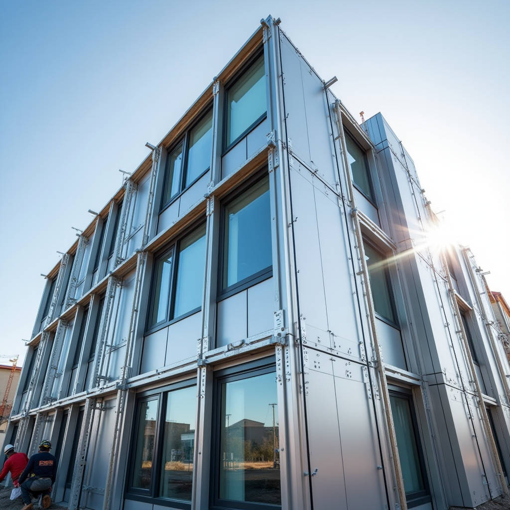
Structural framing in modern facade engineering demands components that balance weight, strength, and long-term corrosion resistance. Among the available profiles, the Aluminum C Channel has become a standard section for curtain wall substructures, perimeter stiffening frames, and adjustable bracket assemblies. Unlike hot-rolled steel channels that add dead load and require galvanizing, extruded aluminum C channels offer a predictable strength-to-weight ratio and integrate cleanly with solid aluminium cladding panels. This article examines how 6061-T6 and 6063-T5 aluminum C channels perform in ventilated facade systems, focusing on deflection limits, thermal movement accommodation, and the fabrication decisions that separate a durable installation from one that requires remedial work within five years. Every data point draws from ASTM B221 tolerances, AAMA 508 testing protocols, and documented project experience with 2.0mm to 3.0mm PVDF-coated solid aluminium sheets.
Why Aluminum C Channel Dominates Facade Subframe Design
The geometry of a C channel provides three flat surfaces for fastening: the web accepts bolt-through connections to primary structure, while the two flanges offer parallel bearing planes for panel attachment brackets or continuous support rails. This three-sided access makes the Aluminum C Channel fundamentally more versatile than rectangular hollow sections or angles when field adjustments are required. A crew can slide T-bolts along the channel slot, reposition brackets by 10mm increments, and lock everything down without drilling additional holes on site.
Weight comparisons tell the practical story. A 100mm deep C channel in 6061-T6 extruded aluminum with a 6mm web thickness weighs approximately 3.8 kg per linear meter. The equivalent steel channel in S275 grade weighs 10.5 kg/m before galvanizing. Across a 20,000-square-meter facade with vertical mullions at 1,200mm centers, that difference amounts to roughly 28 metric tons of dead load removed from the primary structure. Architects working on lightweight steel-frame buildings or retrofits where existing foundations cannot accept additional load find this reduction decisive.
Corrosion performance removes the protective coating variable. Hot-dip galvanized steel channels in coastal or industrial environments develop zinc carbonate patina over time, and any field-cut edge becomes a corrosion initiation point. Aluminum C channel extrusions in 6063-T5 alloy carry their corrosion resistance through the entire cross-section. Mill finish 6063 can serve in C3 environments per ISO 12944-2 classification. For C4 and C5 conditions, anodized or PVDF-coated aluminum channels eliminate the periodic maintenance burden that steel subframes impose on building owners.
6061-T6 vs 6063-T5: Selecting the Right Alloy for Facade Channels
The choice between 6061 and 6063 aluminum for C channel extrusions is not a simple matter of "stronger is better." Each alloy serves distinct roles in facade engineering, and misapplication leads to either unnecessary cost or inadequate performance.
6061-T6 delivers a minimum tensile strength of 260 MPa and yield strength of 240 MPa per ASTM B221. These numbers make it the default choice for primary load-bearing channels: vertical mullions carrying panel weight and wind load, horizontal transoms spanning between floor slabs, and cantilevered bracket arms that offset the cladding plane by 300mm or more from the structural wall. The higher magnesium and silicon content in 6061 also provides better fatigue resistance for channels subjected to cyclic wind loading in high-rise applications.
6063-T5, with a minimum tensile strength of 150 MPa and yield strength of 110 MPa, serves a different purpose. Its lower alloy content allows faster extrusion speeds and more complex cross-sectional geometries. Architects specifying custom C channel profiles with integrated gasket grooves, drainage slots, or aesthetic shadow lines will find 6063-T5 more economical and capable of holding tighter dimensional tolerances. The alloy also accepts anodizing with superior color consistency compared to 6061, which matters when channels remain visible as architectural features rather than being hidden behind cladding panels.
A practical rule from project experience: specify 6061-T6 for any channel that carries calculated bending stress exceeding 55 MPa under service loads. Below that threshold, 6063-T5 provides adequate capacity with roughly 15-20% lower material cost. The Futeng® engineering team routinely applies this distinction when advising on solid aluminium cladding projects where the channel specification directly impacts the overall facade budget.
| Property | 6061-T6 Aluminum C Channel | 6063-T5 Aluminum C Channel | Typical Application |
|---|---|---|---|
| Minimum Tensile Strength (MPa) | 260 | 150 | Structural vs. Architectural |
| Minimum Yield Strength (MPa) | 240 | 110 | Load-bearing capacity |
| Elongation (%) | 8-10 | 8-12 | Ductility for forming |
| Extrusion Complexity | Moderate | High (complex profiles) | Custom geometries |
| Anodizing Response | Good (slight yellow tint) | Excellent (clear silver) | Visible architectural channels |
| Relative Cost per kg | Base | Approx. 15-20% lower | Budget optimization |
| Weldability | Excellent | Good | Fabrication requirements |
| Typical Facade Role | Primary mullions, transoms, brackets | Secondary framing, trim, gasket carriers | Load classification |
Deflection Limits and Wind Load Performance
Facade engineers specify aluminum C channel sections based on two governing criteria: ultimate strength under peak wind pressure and serviceability deflection under frequent wind conditions. The second criterion almost always controls the design. A channel that carries the load without yielding but deflects 25mm at mid-span will telegraph visible waves across the cladding surface, compromise panel joint seals, and create the appearance of a failing facade even when structurally sound.
Industry standards provide clear deflection limits. The AAMA TIR-A9 recommends L/175 for aluminum-framed cladding components, where L is the span between supports. For a typical 3,600mm floor-to-floor mullion span, this translates to a maximum allowable deflection of 20.6mm. European practice under EN 13830 often tightens this to L/200 or 18mm for the same span, particularly when the facade incorporates large-format solid aluminium panels where any substrate curvature becomes immediately visible.
Calculating the required section modulus for a given wind load is straightforward. For a simply supported C channel with uniformly distributed wind load, the moment of inertia (I) required to meet deflection limits follows the formula I = (5 × w × L⁴) / (384 × E × δ), where w is the load per unit length, L is span, E is the elastic modulus of aluminum (approximately 69,000 MPa), and δ is the allowable deflection. A 100mm deep C channel with 50mm flange width and 6mm web thickness typically provides an I-value around 1,200,000 mm⁴, sufficient for wind pressures up to 2.0 kPa at 3,600mm span when combined with appropriate bracket spacing.
Thermal movement introduces a parallel consideration. Aluminum expands at approximately 0.024mm per meter per degree Celsius. A 3,600mm C channel mullion experiencing a 60°C temperature swing from winter night to summer afternoon will elongate by 5.2mm. The channel connection details must accommodate this movement without transferring stress to the solid aluminium cladding panels. Slotted connections at channel ends, with the slot length calculated as 1.5 times the predicted thermal movement, prevent the subframe from buckling or pulling fasteners loose.
Fabrication Tolerances and Quality Control
ASTM B221 governs the dimensional tolerances for extruded aluminum C channels. The standard specifies allowable variation in web thickness, flange width, straightness, and twist. For a channel with a 100mm nominal depth, the allowable straightness deviation is 1.5mm per 1,000mm of length. Twist is limited to 0.5° per 300mm of width, measured as the angular deviation of one flange relative to the other.
These numbers matter because facade subframe alignment directly determines panel flatness. A C channel mullion with 3mm of bow over its length, when installed at 1,200mm centers, will create a visible undulation across the cladding surface. The human eye detects deviations of 3mm over a 2-meter gauge length under raking light conditions. Quality-conscious fabricators straighten extrusions after aging using roller straightening machines that bring the product within 0.5mm per 1,000mm, well inside the ASTM minimum.
Cutting accuracy is equally critical. C channels cut for facade subframes require squareness within 0.5° and length tolerance of ±1.0mm. CNC saws with automatic material feed achieve this routinely. Manual cutting with a chop saw introduces variability that accumulates across the facade grid. On a 50-meter building elevation, cumulative cutting errors of just 0.5mm per channel across 40 vertical mullions produce a 20mm drift at the top corner—enough to misalign panel fastening points and require field rework.
End finishing of cut channels deserves attention. Raw saw-cut edges on aluminum C channels create two problems: sharp burrs that cut installers' hands and damage gaskets, and exposed aluminum that oxidizes differently from the extruded surface. A quick deburring pass with a rotary tool and application of a clear touch-up coating at cut ends prevents both issues. The ISO 12944 corrosion protection framework classifies this as part of the fabrication quality plan for any aluminum component in C3 or higher environments.
Connection Design: Brackets, Fasteners, and Galvanic Isolation
The interface between aluminum C channel and the primary building structure demands careful material pairing. Direct contact between aluminum and carbon steel in the presence of moisture creates a galvanic cell where the aluminum acts as the anode and corrodes preferentially. The standard solution is a physical barrier: either a nylon or EPDM isolation pad between the aluminum channel and steel bracket, or stainless steel fasteners throughout the connection assembly.
AISI 316 stainless steel fasteners provide the most reliable isolation. The electrochemical potential difference between 316 stainless and 6061/6063 aluminum is negligible in atmospheric exposure, and the stainless fastener's higher hardness prevents thread galling during installation. For budget-sensitive projects, hot-dip galvanized steel brackets with a 0.5mm EPDM isolation strip between the bracket and the aluminum C channel back face represent a proven alternative, provided the isolation strip extends 5mm beyond all edges of the steel bracket to prevent water bridging.
Bracket spacing along the C channel follows the bending moment diagram of the wind load. For a simply supported channel, the maximum bending moment occurs at mid-span, so bracket spacing should be uniform rather than concentrated at ends. Typical practice places brackets at 600mm to 900mm centers along the channel length, with the first bracket positioned no more than 150mm from each end to control end rotation.
Thermal expansion joints in long channel runs require a different connection approach. Where two C channel sections meet, a sliding sleeve connection—typically a 200mm long aluminum insert that fits inside both channel ends—maintains axial alignment while permitting 10mm to 15mm of longitudinal movement. One side of the sleeve is fixed with stainless steel screws; the other side has slotted holes that allow the second channel to slide. This detail prevents the clicking and popping noises that building occupants report when fixed connections bind and release under thermal cycling.
Surface Treatment Options for Aluminum C Channel in Facades
Mill finish aluminum C channel carries a natural oxide layer approximately 0.005mm thick. For interior applications or protected cavities within ventilated facades, this provides adequate durability. Exterior exposure demands more.
Anodizing to AA-M10C22A31 (Class I, architectural) builds an oxide layer 0.018mm to 0.025mm thick with hardness approaching 300 HV on the Vickers scale. The anodic coating is integral to the aluminum surface—it cannot peel or delaminate like a paint film. For C channels that remain visible as architectural elements, anodizing in clear, bronze, or black tones provides a consistent metallic appearance that ages gracefully. The limitation is color range: anodizing cannot match the specific RAL or Pantone colors that architects specify for solid aluminium cladding panels.
PVDF (polyvinylidene fluoride) liquid coating bridges this gap. Applied as a two-coat or three-coat system with a total dry film thickness of 30-40 microns, PVDF coatings on aluminum C channels match the color and gloss of adjacent cladding panels exactly. The AAMA 2605 specification governs high-performance PVDF coatings and requires a minimum of 70% PVDF resin in the color coat. Channels coated to this standard withstand 10 years of South Florida exposure with color change (Delta E) below 5 units, per AAMA testing protocols.
Powder coating offers a middle ground. Polyester powder coatings applied at 60-80 microns thickness provide good color retention and mechanical durability at roughly 40% of the cost of PVDF liquid coating. The trade-off is weathering performance: powder coatings typically meet AAMA 2604 rather than AAMA 2605, meaning they are suitable for 5-7 years of exterior exposure before noticeable fading occurs. For C channels in partially protected locations—behind open-joint cladding panels, for example—powder coating represents a rational cost-performance choice.
Integration with Solid Aluminium Cladding Panels
The Aluminum C Channel subframe and the solid aluminium cladding panel form a system, not a collection of independent components. Panel attachment methods divide into two categories: face-fixed and concealed.
Face-fixed systems use stainless steel screws or rivets through the panel face into the C channel flange. The fasteners remain visible, creating a technical aesthetic that some architects embrace for industrial or transportation buildings. The engineering advantage is direct load transfer: wind pressure on the panel travels straight through the fastener into the channel flange with no intermediate components. The disadvantage is that every fastener penetration through the panel creates a potential water entry point, requiring EPDM washers under each screw head and periodic inspection of seal integrity.
Concealed systems use extruded aluminum carriers or cassettes that clip onto the C channel grid. The solid aluminium panel is fabricated with folded returns on all four edges, and these returns engage with the carrier system. From the exterior, only the panel face and the open joints between panels are visible. This approach dominates commercial and institutional facade work because it eliminates exposed fasteners and allows individual panel removal for access to the cavity behind. The C channel grid must be installed to tighter tolerances—typically ±2mm in plane across any 3-meter gauge length—because the concealed clip engagement range is limited to about 5mm of adjustment.
Panel thickness interacts with channel spacing. A 2.0mm solid aluminium panel with stiffening ribs welded to the rear face can span 600mm between C channel supports without visible oil-canning under thermal load. A 3.0mm panel can span 900mm to 1,200mm depending on panel dimensions and rib pattern. The Futeng® manufacturing range includes both thicknesses with PVDF coating applied after forming, ensuring edge coverage that shop-applied coatings on pre-fabricated sheets cannot match.
Cost Structure and Procurement Strategy
The cost of aluminum C channel for facade work breaks down into material, fabrication, surface treatment, and logistics components. Material cost tracks the London Metal Exchange (LME) aluminum price plus an extrusion premium that varies with alloy and profile complexity. As of current market conditions, 6063-T5 C channel in standard architectural sizes ranges from $4.50 to $6.80 per kg depending on quantity and profile complexity. 6061-T6 adds approximately $0.80 to $1.20 per kg.
Fabrication costs—cutting to length, drilling, notching, and deburring—add $1.50 to $3.00 per kg for typical facade subframe packages. Surface treatment costs vary widely: anodizing adds $2.00 to $4.00 per kg, powder coating $3.00 to $5.00, and PVDF liquid coating $6.00 to $10.00. The wide range reflects the difference between processing standard stock lengths and custom-cut pieces where the surface area-to-weight ratio is higher.
Procurement strategy should account for these variables. Ordering full 6,000mm stock lengths and performing fabrication in a local workshop reduces per-unit cost but requires investment in cutting and handling equipment. Ordering fabricated-to-length channels from the extrusion mill or a specialist fabricator costs more per piece but eliminates on-site cutting waste and quality variability. For projects exceeding 5,000 kg of aluminum channel, mill-direct ordering with fabrication included typically yields the best combination of price and quality assurance.
ASTM B221 remains the foundational specification for extruded aluminum channel tolerances. Engineers should reference the current edition for allowable dimensional variation, mechanical properties by alloy and temper, and quality documentation requirements. The standard is available through ASTM International.
Common Failure Modes and How to Avoid Them
Experience across multiple facade projects reveals recurring problems with aluminum C channel subframes. The most damaging is galvanic corrosion at the interface between aluminum channels and steel building structure. The fix is straightforward—isolation pads and stainless fasteners—but the failure occurs when value engineering removes these items from the specification. The resulting corrosion products (white, powdery aluminum oxide) expand with enough force to distort the C channel flange and crack adjacent panel joints. Remediation requires removing cladding panels, cutting out corroded channel sections, and reinstalling with proper isolation—at roughly five times the cost of doing it correctly the first time.
Inadequate allowance for thermal movement ranks second. Fixed connections at both ends of a long C channel run will cause the channel to buckle laterally when temperature rises. The buckling force is substantial: a 100mm × 50mm C channel constrained at both ends develops approximately 18 kN of axial force for a 50°C temperature rise. This force can shear fasteners or deform steel support brackets. The solution is sliding connections at one end of every channel run longer than 6 meters, with the sliding capacity calculated for the expected temperature range at the project location.
Third is fastener pull-through in thin channel flanges. A C channel with a 3mm flange thickness can experience pull-through failure when a screw in tension loads a small area. The solution is either specifying channels with thicker flanges (5mm minimum for structural connections) or using stainless steel backing plates that spread the fastener load across a larger area of the aluminum flange. The Aluminum Association design manual provides pull-through capacity calculations for various flange thicknesses and fastener types.
Fourth is fatigue cracking at notch locations. When C channels are notched to fit around structural obstructions, the sharp corner of the notch creates a stress concentration. Under cyclic wind loading, cracks initiate at the notch root and propagate across the flange. The preventive measure is a minimum 6mm radius at all notch corners, specified on fabrication drawings and verified during incoming inspection. A radius tool gauge costing less than $20 prevents a failure that can cost tens of thousands to remediate.
Specification Writing for Aluminum C Channel in Facade Packages
A tight specification prevents substitution of inappropriate material. The key elements to include:
- Alloy and temper: Specify 6061-T6 or 6063-T5 per ASTM B221, with the choice tied to the structural engineer's calculations. Do not accept "architectural aluminum" as a generic description.
- Dimensional tolerances: Reference ASTM B221 for extrusion tolerances. Add project-specific flatness requirements: 0.5mm per 1,000mm straightness, 0.5° maximum twist.
- Surface treatment: State the applicable AAMA standard (2604 or 2605) for coatings, or AA-M10C22A31 for anodizing. Include the required coating thickness and the color reference standard.
- Fabrication accuracy: Length tolerance ±1.0mm, end squareness within 0.5°, hole position tolerance ±0.5mm.
- Isolation requirements: Mandate physical separation between aluminum channels and dissimilar metals. Specify isolation pad material, thickness, and edge overhang dimensions.
- Quality documentation: Require mill test certificates showing chemical composition and mechanical properties for each heat of aluminum. Require coating thickness measurements and adhesion test results for finished channels.
The specification should also address handling and storage. Aluminum C channels stored in contact with wet ground or uncovered in rain will develop water staining that, while not structurally significant, creates aesthetic issues if channels are visible. Storage on timber dunnage under cover, with channels separated by spacers to allow air circulation, prevents this problem at negligible cost.
For projects where the aluminum C channel subframe supports solid aluminium cladding panels, the specification should require a mock-up installation. A 3-meter by 3-meter mock-up, built using the actual channel sections, brackets, fasteners, and panels specified for the project, reveals fit issues, tolerance stack-ups, and installation sequence problems before they propagate across the full facade. The mock-up cost—typically $3,000 to $8,000—is a fraction of the rework cost on a large elevation.
Selecting and specifying aluminum C channel for facade subframes is fundamentally an exercise in matching the component to the mechanical and environmental demands of the specific project. The alloy choice, surface treatment, connection detailing, and fabrication accuracy all contribute to a system that either performs quietly for decades or generates callbacks within the first two years. The technical data, standards references, and practical guidance assembled here provide a framework for making those decisions with confidence.