Aluminum U Channel Thermal and Structural Design for Curtain Wall Facades
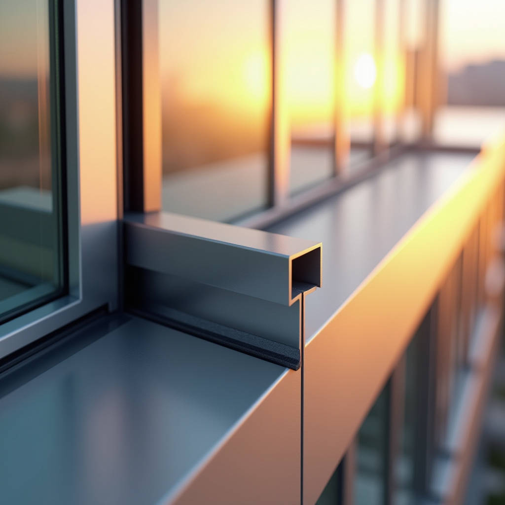
When a curtain wall contractor specifies an Aluminum U Channel as a perimeter trim, stiffener, or glazing pocket, the decision usually comes down to alloy grade, wall thickness, and finish compatibility. But what gets overlooked — and what causes the most callbacks — is the thermal expansion behavior of the aluminum itself. A 3-meter length of 6063-T5 Aluminum U Channel will grow by roughly 1.8 mm for every 25°C temperature swing. Multiply that across a 40-meter building elevation, and the cumulative movement can exceed 20 mm if the joints are not engineered correctly. This article focuses on the structural and thermal design considerations that determine whether an Aluminum U Channel performs as a reliable component in high-rise facade systems or becomes a source of chronic cracking, sealant failure, and water ingress. We draw on real project data, ASTM standards, and field observations from projects where Futeng® supplied custom-extruded aluminum profiles for curtain wall applications across Southeast Asia and the Middle East.
Why Aluminum U Channel Shows Up in Curtain Wall Design
An Aluminum U Channel serves multiple roles in a unitized or stick-built curtain wall. It acts as a receptor for glass panels, a horizontal or vertical stiffener behind perforated panels, a perimeter closure at slab edges, or a shadow box frame. The open cross-section — two parallel legs connected by a web — makes it easy to assemble, fasten, and integrate with gaskets and pressure plates. But the simplicity of the profile masks the complexity of the engineering. Unlike a closed box section, a U-shaped channel has asymmetric torsional stiffness. When loaded off-axis, the legs can twist. When restrained at both ends and subjected to solar radiation, compressive stresses can buckle the web. These failure modes are well-documented in facade engineering literature, yet they recur on job sites because the Aluminum U Channel is often treated as a commodity item rather than a designed structural element.
The alloy selection alone dictates how the channel behaves under cyclic thermal loads. 6063-T5 is the most common architectural grade, offering good extrudability and a smooth surface finish suitable for anodizing. 6061-T6 provides higher tensile strength — approximately 310 MPa versus 185 MPa for 6063-T5 — but is harder to extrude into thin-walled profiles and costs more. For a typical 50 x 25 x 2.5 mm Aluminum U Channel used as a glazing bead, 6063-T5 is adequate. For a 100 x 50 x 4 mm channel functioning as a mullion stiffener in a high-wind zone, 6061-T6 becomes the safer choice. The table below summarizes the key mechanical properties that drive these decisions.
| Property | 6063-T5 | 6063-T6 | 6061-T6 |
|---|---|---|---|
| Tensile Strength (MPa) | 185 | 240 | 310 |
| Yield Strength (MPa) | 145 | 215 | 276 |
| Elongation (%) | 12 | 8 | 10 |
| Thermal Expansion (10⁻⁶/°C) | 23.4 | 23.4 | 23.6 |
| Typical Wall Thickness Range (mm) | 1.2–3.0 | 1.5–3.0 | 2.0–6.0 |
| Anodizing Response | Excellent | Good | Fair (slight yellow tint) |
Thermal Movement: The Silent Design Variable
Aluminum expands at roughly 23.4 × 10⁻⁶ per degree Celsius. For an Aluminum U Channel fixed between two anchor points, the linear expansion follows a simple formula: ΔL = α × L₀ × ΔT. A 6-meter length subjected to a 40°C temperature rise (from 10°C at dawn to 50°C on a dark PVDF-coated surface under direct sun) elongates by approximately 5.6 mm. If the channel is rigidly fastened at both ends without an expansion joint, the induced compressive stress can reach 130 MPa — enough to buckle a 2 mm web in 6063-T5. This is not a theoretical edge case. We have seen it on projects in Dubai and Riyadh, where mid-summer surface temperatures on dark-colored aluminum cladding routinely exceed 80°C.
The solution involves three strategies, often used in combination. First, slotted connections: the Aluminum U Channel is fastened through elongated holes that permit longitudinal movement while restraining the channel laterally. Second, segmented lengths: instead of a single continuous 6-meter piece, the channel is broken into 2.5–3 meter segments with 8–10 mm gaps, covered by a sliding splice sleeve. Third, material pairing: using a stainless steel or aluminum slip connector inside the channel that allows differential movement. The American Architectural Manufacturers Association (AAMA) publishes guidelines on thermal movement accommodation in its TIR-A14 document, which is worth consulting for any facade project exceeding 20 meters in height.
Joint Design for Movement Accommodation
The joint gap between two adjacent Aluminum U Channel segments must be sized for the worst-case thermal scenario. A common rule of thumb is 1.5 mm per meter of channel length, but this oversimplifies the problem. The actual gap should account for the maximum expected temperature range at the project location, the surface color (dark PVDF absorbs more solar radiation), and the installation temperature. If the channel is installed at 35°C, it will contract when temperatures drop to 5°C, pulling the joint open. If installed at 15°C, it will expand and close the gap. The joint sealant must accommodate both extremes without cohesive failure. Silicone sealants with ±50% movement capability are standard; hybrid polyurethane sealants with ±25% capability are riskier for this application.
Finish Compatibility with Aluminum U Channel Geometry
The U-shaped cross-section creates challenges for surface finishing that flat panels do not face. The inside corners where the legs meet the web are difficult to clean, etch, and coat uniformly. In anodizing, the electrical field distribution inside a U-channel is non-uniform, leading to thinner oxide layers in the interior corners — sometimes 30–40% below the specified minimum. This matters because those corners are precisely where condensation collects and corrosion initiates. For architectural applications exposed to weather, we specify a minimum of 20 microns of anodic coating (AA-M12C22A31 per The Aluminum Association standards) and require the extruder to provide cross-section micrographs of corner coating thickness as part of the first-article inspection.
PVDF (polyvinylidene fluoride) coatings — typically 70% PVDF resin with 30% acrylic, applied at 25–35 microns dry film thickness — offer better corrosion resistance than anodizing for coastal and industrial environments. But the application process for an Aluminum U Channel requires careful racking. If the channel is hung with the open side facing away from the spray nozzles, the interior surfaces receive insufficient coating. The standard specification from AAMA 2605 requires a minimum of 25 microns on all significant surfaces, which includes the interior of a U-channel if it is visible or exposed. For channels used as interior stiffeners within a closed panel assembly, AAMA 2604 (minimum 20 microns) may be acceptable, but this must be confirmed in the project specification.
| Finish Type | Standard | Min. Thickness | Coastal Suitability | Relative Cost |
|---|---|---|---|---|
| Clear Anodized | AA-M12C22A31 | 20 μm | Moderate (≥3 km from coast) | 1.0× |
| PVDF (2-coat) | AAMA 2604 | 20 μm | Good | 1.8× |
| PVDF (3-coat) | AAMA 2605 | 30 μm | Excellent | 2.3× |
| Powder Coated | Qualicoat Class 2 | 60 μm | Moderate | 1.3× |
| Mill Finish | N/A | N/A | Not recommended for exterior | 0.7× |
Structural Design Checks for Aluminum U Channel in Facades
An Aluminum U Channel used as a secondary structural member in a curtain wall must satisfy three design checks: bending strength, deflection, and local buckling. The bending check follows the standard formula M / S ≤ Fₐ, where M is the applied moment, S is the section modulus, and Fₐ is the allowable bending stress (typically 0.6 × yield strength for aluminum per the Aluminum Design Manual). The deflection limit for a channel supporting glass is usually L/175 or 19 mm, whichever is smaller, per ASTM E1300. Local buckling of the legs or web is governed by the width-to-thickness ratio. For a 6063-T5 Aluminum U Channel, the web slenderness limit (b/t) is approximately 35 for a simply supported edge condition. Exceeding this requires a reduced allowable stress or a stiffened design.
Wind load is the dominant lateral load for facade channels. On a 50-story building, the design wind pressure at the top corners can reach 3.5 kPa or more. A 50 × 25 × 2 mm Aluminum U Channel spanning 1.2 meters between mullions and supporting a 1.0 m² glass panel would experience a bending moment of roughly 0.63 kN·m under a 3.5 kPa wind load. The section modulus of this channel is about 1.2 cm³, giving a bending stress of 525 MPa — far exceeding the allowable for any aluminum alloy. This simple calculation explains why an Aluminum U Channel in a high-rise facade is rarely the primary load-bearing element; it works in concert with the mullion, transom, and pressure plate as part of a built-up section.
Connection Design and Fastener Selection
The connection between an Aluminum U Channel and the primary structure deserves as much attention as the channel itself. Stainless steel fasteners (A2 or A4 grade, equivalent to 304 or 316) are mandatory to avoid galvanic corrosion. The fastener spacing along the channel should not exceed 300 mm for wind-loaded applications, and edge distance should be at least 1.5 times the fastener diameter. For slotted connections that permit thermal movement, the slot length must equal the expected movement plus the fastener diameter, and a nylon or PTFE washer should be placed between the fastener head and the aluminum to reduce friction and prevent galling.
Supply Chain Considerations for Custom Aluminum U Channel
Procuring an Aluminum U Channel for a large facade project involves more than picking a standard size from a catalog. Custom extrusion dies cost between $1,500 and $4,000 depending on profile complexity and diameter. Lead times for die fabrication range from 2 to 6 weeks, followed by sample extrusion and quality approval. The minimum order quantity for a custom run is typically 300–500 kg, though some mills accept smaller runs at a premium. For projects in the Middle East, where we have sourced profiles through Futeng® for several high-rise cladding packages, the total lead time from die approval to delivery of finished, coated channels can be 10–14 weeks. This timeline must be built into the project schedule from day one.
Standard mill lengths are 6 meters (20 feet), but shipping containers are typically 5.9 meters internally, so 5.8-meter lengths are more practical for export. For channels longer than 3 meters, flatness tolerances become critical. The Aluminum Association specifies a maximum bow of 1.5 mm per 300 mm of length for architectural extrusions, but tighter tolerances — 0.8 mm per 300 mm — are achievable with post-extrusion straightening and are worth specifying for visible trim applications.
Quality Control and On-Site Verification
Before an Aluminum U Channel leaves the factory, the following checks should be documented in the mill test certificate: alloy composition (via optical emission spectrometry), tensile properties (per ASTM B221/B221M), dimensional tolerances (per ANSI H35.2), and coating thickness and adhesion (per AAMA 2605 or relevant standard). On site, the receiving inspection should verify the dimensions with a calibrated caliper — particularly the web thickness and leg height, which are the most common points of deviation. A simple go/no-go gauge made from a sample of the mating gasket or glass panel can catch fitment issues before installation begins.
One often-missed check is the straightness of long channels. A 5.8-meter length with a 12 mm bow will be impossible to align with the mullion grid, forcing the installer to either force-fit it (inducing permanent stress) or reject it on site (causing delays). A straightedge and feeler gauge check takes 30 seconds per piece and saves hours of rework.
Practical Recommendations for Specifiers and Contractors
Based on project experience across multiple climate zones, we offer the following guidance for anyone specifying or procuring an Aluminum U Channel for curtain wall and cladding applications:
- Alloy selection: Use 6063-T5 for interior trim, glazing beads, and non-structural applications. Use 6063-T6 or 6061-T6 for channels that carry glass weight or wind loads. Confirm the temper with the supplier — T4 material (naturally aged) is sometimes substituted and has significantly lower strength.
- Wall thickness: Never go below 1.5 mm for any channel exposed to wind or handling loads. For structural channels, 2.5–3.0 mm is the practical minimum. The cost difference between 2.0 mm and 2.5 mm is roughly 15–20% in material, but the stiffness gain is nearly 100%.
- Thermal movement: Calculate the expected movement for the project location and design the joint system accordingly. Do not rely on rules of thumb. Document the assumed installation temperature range in the method statement and verify it during installation.
- Finish specification: For coastal projects (within 3 km of salt water), specify PVDF 3-coat (AAMA 2605) or a marine-grade anodizing with minimum 25 microns. Include a requirement for corner coating thickness verification in the quality plan.
- Supplier qualification: Request cross-section micrographs of the anodizing or coating thickness, not just flat-panel test coupons. The geometry of a U-channel affects finish quality, and a supplier that cannot demonstrate control over this variable is a risk.
- On-site storage: Store Aluminum U Channel lengths horizontally on padded racks, protected from rain and construction dust. Interleaving with kraft paper prevents scratching. Channels stored vertically against a wall will develop permanent bow within days.
The Aluminum U Channel is a deceptively simple profile. Its performance in a high-rise facade depends on decisions made months before installation — alloy grade, temper, wall thickness, finish system, joint design, and fastener specification. Getting these right requires close coordination between the architect, facade engineer, and extrusion supplier. When the thermal and structural analysis is done properly, the channel disappears into the building envelope, doing its job without drawing attention. That is the mark of a well-engineered facade component.