Aluminum Hat Channel Engineering for Rainscreen Substructure Span and Thermal Performance
When a rainscreen facade system goes up on a commercial tower, the visible surface gets all the attention. Architects and clients focus on panel flatness, color consistency, and joint alignment. But behind every square meter of solid aluminum cladding panel sits a substructure that determines whether the facade will stay straight through decades of thermal cycling, wind gusts, and building movement. The Aluminum Hat Channel is the backbone of that substructure. Its job sounds simple: span between the primary structural frame and the back of the cladding panel, creating a ventilated cavity while transferring wind loads. In practice, the hat channel dictates installation speed, long-term flatness, and whether a project hits its thermal performance targets. Getting the profile geometry, alloy selection, and attachment method right matters more than most specifiers realize.
What Makes a Hat Channel Different from Other Sub-Girts
The name comes from the cross-section. Two horizontal flanges extend outward like a brim, two vertical legs rise from the flanges, and a flat top surface connects them. This shape creates a standoff from the structural substrate. Unlike a simple C-channel or Z-girt, the hat profile provides two parallel bearing surfaces: the flanges that fasten to the substrate and the top face that receives the cladding panel clip or rail. The open geometry also allows insulation to run continuously behind the channel without the thermal bridges that solid rectangular profiles create.
In aluminum rainscreen applications, the Aluminum Hat Channel typically comes in 6063-T6 or 6061-T6 extrusions. 6063-T6 offers a yield strength around 170 MPa with good corrosion resistance and anodizing quality. 6061-T6 pushes yield strength closer to 240 MPa, which matters when spans increase or wind loads climb. The choice between them should be driven by structural calculations, not habit. A project in coastal Florida with hurricane-level wind pressures will demand different section properties than a low-rise office park in inland Texas.
Alloy Decisions That Shape Performance
Extruded aluminum hat channels dominate the architectural market, but the alloy conversation goes deeper than 6063 versus 6061. Temper designation matters. T5 temper (cooled from an elevated temperature shaping process and artificially aged) provides adequate strength for most vertical cladding applications. T6 temper (solution heat-treated and artificially aged) delivers higher strength and better stress-corrosion resistance. For projects within 5 kilometers of saltwater, T6 becomes the safer specification regardless of calculated loads.
Some manufacturers also offer 6005A-T61 extrusions, which balance the extrudability of 6063 with strength approaching 6061. The profile's wall thickness typically ranges from 1.5mm to 3.0mm depending on the section depth and span. A 50mm-deep hat channel with 2.0mm wall thickness in 6063-T6 might span 1,200mm between supports at moderate wind loads. Push that span to 1,800mm and the section either needs to deepen or switch to 6061-T6. These are the calculations that keep facade engineers awake, and they are the reason generic "aluminum hat channel" pricing requests without span and load data rarely produce useful quotes.
Thermal Bridging and the Cavity Problem
The ventilated cavity behind solid aluminum cladding panels serves two purposes: it drains water that penetrates the panel joints, and it drives a chimney effect that pulls heat out of the wall assembly in summer. But every aluminum hat channel that bridges from the cold exterior to the warm interior structure creates a thermal short circuit. The thermal conductivity of aluminum runs around 160 W/m·K, which is roughly 1,000 times higher than the mineral wool insulation that fills the cavity.
Engineers address this with thermal breaks. A common approach uses a two-part hat channel: an aluminum outer section mechanically fastened to an aluminum inner section with a rigid PVC or polyamide thermal separator between them. The separator material has thermal conductivity below 0.3 W/m·K. The trade-off is structural. The thermal break reduces the composite section's moment of inertia, so either the profile must deepen or support spacing must tighten. A thermally broken Aluminum Hat Channel might add 15-25% to the substructure material cost while cutting thermal transmittance through the sub-girt by 40-60%. For projects targeting LEED or Passive House certification, that math usually works.
Wind Load Transfer Through the Hat Channel Assembly
Wind hitting a building facade creates positive pressure on the windward face and negative pressure (suction) on the leeward face and corners. The Aluminum Hat Channel transfers these loads from the cladding panel, through the panel clip or rail, into the hat channel top flange, down through the channel legs, and out through the base flanges into the structural substrate. Every connection point in that chain needs engineering attention.
The panel clip attachment to the hat channel top face typically uses stainless steel self-drilling screws or rivets. Screw spacing along the channel runs 300-600mm depending on panel size and wind zone. The hat channel's attachment to the substrate uses expansion anchors in concrete, screw anchors in steel studs, or through-bolts in structural steel. The base flange width matters here: a 40mm-wide flange gives more edge distance for anchors than a 30mm flange, which can be the difference between passing and failing pull-out calculations in cracked concrete.
A useful reference for wind load design is ASCE 7 Minimum Design Loads for Buildings, which provides the pressure coefficients that drive attachment spacing calculations. For aluminum member design, the Aluminum Design Manual from the Aluminum Association gives allowable stress values for extruded sections.
Corrosion Compatibility Across the Fastener Chain
Aluminum hat channels in exterior wall assemblies sit in a moist, sometimes salty environment. The aluminum itself resists corrosion through its natural oxide layer, but the fasteners that connect it to steel substrates create galvanic cells. Stainless steel fasteners (300-series) are the standard solution, but the grade matters. Type 304 works inland. Within 5 kilometers of coastline, Type 316 becomes necessary. The cost difference is modest—maybe $0.05 per fastener—but the failure cost of corroded connections inside a completed rainscreen is enormous.
The interface between the aluminum hat channel base flange and the substrate also needs isolation. A thin layer of bituminous paint or a PVC isolation pad prevents direct aluminum-to-steel contact. This detail appears in the AAMA 307 standard for voluntary performance requirements for aluminum curtain wall and storefront framing systems, which addresses galvanic corrosion prevention in exterior wall assemblies.
Hat Channel Dimensions and Their Structural Implications
Standard Aluminum Hat Channel sizes vary by manufacturer and region, but common depths range from 25mm to 100mm, with flange widths from 30mm to 60mm. The table below shows typical section properties for a range of hat channel sizes in 6063-T6, which specifiers can use for preliminary sizing before running full calculations.
| Channel Depth (mm) | Flange Width (mm) | Wall Thickness (mm) | Moment of Inertia Ix (cm⁴) | Section Modulus Sx (cm³) | Approx. Weight (kg/m) | Typical Max Span (mm)* |
|---|---|---|---|---|---|---|
| 25 | 35 | 1.8 | 2.1 | 1.7 | 0.45 | 800 |
| 40 | 40 | 2.0 | 5.8 | 2.9 | 0.72 | 1,100 |
| 50 | 45 | 2.0 | 9.4 | 3.8 | 0.88 | 1,300 |
| 60 | 50 | 2.5 | 18.2 | 6.1 | 1.35 | 1,600 |
| 80 | 55 | 2.5 | 35.6 | 8.9 | 1.75 | 2,000 |
| 100 | 60 | 3.0 | 68.4 | 13.7 | 2.45 | 2,400 |
*Maximum spans are indicative for vertical cladding support at moderate wind loads (1.5 kPa). Always verify with project-specific structural calculations.
These values assume the hat channel is oriented with the open face toward the substrate, which is the standard rainscreen installation. Flipping the channel changes the section properties and should only be done under explicit engineering direction.
Roll-Formed Versus Extruded Aluminum Hat Channels
Most architectural hat channels are extruded, but roll-formed aluminum hat channels exist in the market and deserve comparison. Roll forming starts with aluminum coil stock, typically 5052-H32 or 3003-H14, which is progressively bent through a series of rollers into the hat profile. The process is fast and produces consistent sections at lower cost than extrusion for high-volume runs.
The trade-offs matter. Roll-formed sections have uniform wall thickness set by the starting coil gauge, typically 0.040" to 0.125" (1.0mm to 3.2mm). Corner radii are larger than extrusions because the metal must bend rather than flow. More critically, roll-formed hat channels lack the integral stiffening ribs and screw bosses that extruded profiles can incorporate. The alloy selection is also narrower: 5052-H32 offers yield strength around 195 MPa, which sits between 6063-T6 and 6061-T6, but its magnesium content makes it less suitable for some coastal environments than 6063-T6.
For architectural rainscreen applications where the hat channel is visible at open joints or where precise dimensional tolerances matter, extrusion remains the preferred method. The AAMA 611 standard for anodized architectural aluminum provides tolerance guidelines that extruders follow for these profiles.
Installation Sequence and Quality Control Checkpoints
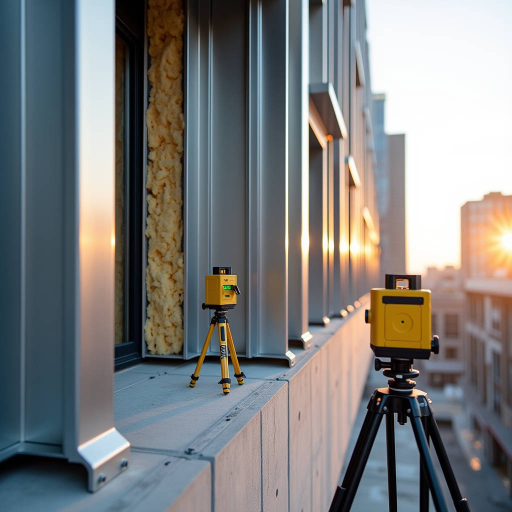
The Aluminum Hat Channel installation sequence on a typical rainscreen project follows a logical order, but the quality control checkpoints are where projects succeed or fail. The first step is substrate survey. Concrete slabs and steel studs are never perfectly flat, and the hat channel must accommodate deviations. Laser scanning the substrate before layout identifies areas where shimming will be required. Packing out a hat channel by more than 10mm with shims changes its effective span and introduces bending moments that the original calculation may not have considered.
Layout comes next. Hat channels typically run vertically on the substrate, with horizontal spacing matching the cladding panel module width. A 1,200mm-wide panel might use hat channels at 600mm centers, with each panel spanning across two channels. The layout must account for building movement joints, window openings, and the starting edge condition. A mistake in the first channel's position propagates across the entire elevation.
Fastening follows layout. Each base flange receives anchors at the calculated spacing, typically 400-600mm on center. The anchor must develop full pull-out capacity in the substrate, which means correct embedment depth and edge distance. On steel stud substrates, the screw must penetrate the stud by at least three thread pitches. On concrete, expansion anchors need minimum edge distances of 100mm or more depending on anchor diameter. These numbers come from anchor manufacturer data, not from the hat channel supplier.
Alignment verification is the checkpoint most often skipped. After fastening a row of hat channels, a straightedge across their top faces should show no more than 2mm deviation over any 3-meter length. This tolerance matters because the cladding panel clips or rails that attach to the hat channel top face will telegraph any misalignment directly into the visible panel surface. A 3mm deviation in the hat channel plane can produce visible waviness in a facade with tight joint tolerances. Suppliers like Futeng® who provide both solid aluminum cladding panels and compatible substructure profiles can offer integrated tolerance guidance, but the installer's quality control on the hat channel alignment ultimately determines the finished facade's flatness.
Thermal Movement Accommodation
Aluminum expands at roughly 0.024mm per meter per degree Celsius. A 3-meter length of Aluminum Hat Channel installed at 10°C will grow by about 2.9mm when the cavity temperature reaches 50°C on a summer afternoon. If both ends of the channel are rigidly fixed, that expansion turns into compressive stress in the channel and shear stress in the fasteners. Over thousands of thermal cycles, the fasteners can loosen or the channel can buckle between anchor points.
The solution is to treat one end of each hat channel length as a fixed point and the other as a sliding connection. Slotted holes in the base flange at the sliding end allow the channel to expand and contract without fighting the fasteners. The slot length should equal the calculated thermal movement at the project's design temperature range plus a safety margin. For a 3-meter channel with a 60°C temperature swing, a 4-5mm slot provides adequate relief. The sliding connection still needs to transfer wind loads in the out-of-plane direction, so the fastener must clamp the flange firmly against the substrate while allowing in-plane movement. Nylon washers under the fastener head reduce friction at the sliding interface.
Cost Structure and Value Engineering Considerations
The Aluminum Hat Channel itself represents a modest fraction of the total rainscreen assembly cost. Material costs for a standard 50mm x 45mm x 2.0mm extruded hat channel in 6063-T6 run roughly $8-15 per linear meter depending on volume and finish. The installed cost, including fasteners, shims, thermal isolation, and labor, typically lands between $25-45 per linear meter. On a facade with hat channels at 600mm centers, that translates to $40-75 per square meter of wall area just for the vertical sub-girt system.
Value engineering efforts often target the hat channel spacing first. Widening the spacing from 600mm to 900mm cuts the linear meter count by one-third, but it also increases the span that the cladding panel must handle between supports. The panel itself may need to thicken from 2.5mm to 3.0mm to maintain flatness at the wider span, which adds roughly $8-12 per square meter in panel material cost. The net savings depend on the specific panel and channel combination, and the calculation should account for the full system, not just the hat channel line item.
Another cost lever is the finish. Mill-finish aluminum hat channels work for concealed applications where the channel sits entirely behind the cladding. If the hat channel is visible at open joints or perforated panel areas, an anodized or PVDF-coated finish adds $3-8 per linear meter. The decision should be driven by aesthetics and corrosion requirements, not by default specification habits.
Specifying Hat Channels for International Projects
Projects that source Aluminum Hat Channel from international suppliers face additional complexity. Different markets use different alloy designation systems. The European EN 755 standard covers extruded aluminum profiles, with alloys like EN AW-6063 corresponding to the U.S. 6063. Japan uses JIS H4100 with alloy A6063S-T5. China's GB/T 5237 standard covers aluminum alloy building profiles. A specification that simply says "aluminum hat channel" without the alloy designation, temper, and reference standard is an invitation for substitution.
Dimensional tolerances also vary. The Aluminum Association publishes standard tolerances for extruded profiles in the U.S. market. European projects reference EN 12020 for precision extrusions. The differences are small—typically fractions of a millimeter—but they can affect fit-up when hat channels from one source must align with cladding clips from another.
Surface treatment specifications need equal precision. An anodized finish should reference the coating standard (AAMA 611 in the U.S., Qualanod in Europe), the anodizing class (Class I or Class II), and the coating thickness in microns. A PVDF coating should specify the resin system (70% PVDF minimum per AAMA 2605), the coating thickness (minimum 30 microns for a two-coat system, 40 microns for three-coat), and the color reference standard.
When the Hat Channel Becomes the Limiting Factor
Most facade failures that trace back to the substructure involve one of three mechanisms: fastener pull-out from the substrate, buckling of the hat channel under compression, or excessive deflection under wind load that causes visible panel movement. The first two are structural failures that building codes are designed to prevent. The third is a serviceability failure that codes may not directly address but that building occupants notice immediately when panels rattle in the wind or show visible waviness.
The deflection limit for Aluminum Hat Channel supporting cladding should be tighter than the typical L/360 used for floor joists. A limit of L/500 or even L/600 for the out-of-plane deflection under design wind load keeps the cladding panel plane stable and prevents joint sealant from overstressing. This tighter limit often controls the hat channel section size more than the strength calculation does. A channel that is strong enough at L/360 may need to be one size deeper to satisfy L/500.
The interaction between the hat channel and the cladding panel also deserves attention. A solid aluminum panel at 2.5mm or 3.0mm thickness has its own stiffness, and the panel can span between hat channel supports. But the panel's deflection under wind load adds to the hat channel's deflection. The total system deflection—panel plus channel—should stay within the architectural tolerance for the facade plane. This means the hat channel deflection limit may need to be even tighter than L/600 if the panel itself contributes significant deflection at the chosen support spacing.
Getting the substructure right is not glamorous work. It does not win design awards. But the Aluminum Hat Channel is where engineering discipline meets installation reality. The projects that look flat and stay flat for 20 years are the ones where someone took the time to calculate the hat channel spans, specify the right alloy and temper, detail the thermal breaks, and verify the alignment before the panels went up. The projects that develop waviness, rattles, and corrosion stains are the ones where the hat channel was an afterthought.