Aluminum L Profile Engineering for Solid Cladding Subframe Load Paths and Alloy Selection
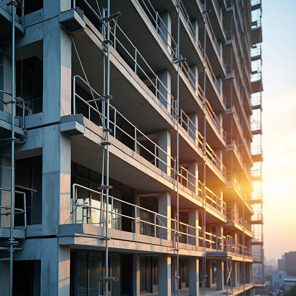
When a facade contractor calls about panel edge deformation on a 22-story curtain wall in Dubai, the post-mortem rarely points to the panel itself. The failure trace leads backward through the support system until it lands on one component that nobody bothered to spec properly: the Aluminum L Profile. These extruded aluminum angles operate as the quiet interface between the visible cladding surface and the building's structural skeleton. A 3.0mm solid aluminum panel might carry a wind load of 2.4 kPa without yielding, but if the L-profile subframe behind it twists under the same pressure, the entire assembly loses its design stiffness. The result is not catastrophic collapse but something more insidious: visible waviness across the facade, leaking gaskets, and a warranty claim that pits the installer against the extruder. This article examines how Aluminum L Profile selection intersects with solid aluminum cladding performance, specifically addressing alloy grade decisions, section modulus requirements, thermal movement accommodation, and the supply chain realities that determine whether a project stays on schedule or drifts into costly rework.
Why the Aluminum L Profile Matters More Than the Panel
Solid aluminum cladding panels in 2.5mm and 3.0mm thicknesses carry impressive span ratings when tested in isolation. A 5052-H32 panel at 3.0mm can clear a 1,200mm span under uniform wind load with deflection staying within L/60. But the panel never works alone. It attaches to a subframe grid, and that grid relies on Aluminum L Profile sections to transfer loads from the panel face into the building's primary structure. The load path is straightforward: wind hits the panel, the panel bears on the L-profile flange, the profile transfers shear and bending into the anchor system. When the profile is undersized, two failure modes emerge. The first is flange bending, where the outstanding leg of the L deflects under panel reaction, creating a soft spot in the support line. The second is torsional buckling of the entire section, which occurs because L-profiles have low torsional rigidity compared to closed sections like rectangular tubes.
The irony is that many project specifications run to 40 pages on panel flatness, PVDF coating thickness, and color consistency, then reduce the subframe to a single line: "Aluminum L Profile, 50x50x3mm, 6063-T5." That generic callout ignores the specific demands of the project's wind zone, the panel weight, and the fixing method. A 50x50x3mm equal-leg angle in 6063-T5 has a section modulus around 1.2 cm³ in the strong axis. Under a 2.0 kPa wind load on a 1.2m x 1.2m panel, the reaction at each intermediate support approaches 1.4 kN. The bending stress in that profile can exceed 160 MPa, which is above the allowable design stress for 6063-T5 per The Aluminum Association design guidelines. The math does not lie, but it does get ignored when value engineering trims the subframe budget.
Alloy Selection: 6063-T5 vs 6061-T6 and the Strength Gap
The aluminum extrusion market offers L-profiles in several alloys, but two dominate facade subframe work: 6063-T5 and 6061-T6. The numbers look similar on a datasheet, and that is precisely the trap. 6063-T5 delivers a minimum yield strength of 110 MPa and ultimate tensile strength around 150 MPa. It extrudes beautifully, takes anodizing with excellent color consistency, and costs less per kilogram. For interior applications or low-rise facades in mild wind zones, 6063-T5 performs adequately. The problem starts when the profile goes onto a high-rise in a coastal typhoon zone or anywhere with design wind pressures exceeding 1.5 kPa.
6061-T6 brings a minimum yield strength of 240 MPa and ultimate tensile strength of 260 MPa. That is more than double the yield strength of 6063-T5. The section modulus requirement drops proportionally, meaning a smaller, lighter profile can carry the same load. Alternatively, the same profile size provides a much larger safety margin. The trade-off is cost: 6061-T6 typically runs 15-25% more per kilogram than 6063-T5, and the extrusion process requires tighter die control because 6061 is less forgiving during quenching. Some extruders push back on tight-tolerance 6061-T6 L-profiles because the scrap rate climbs when the press speed is not dialed in perfectly. The procurement manager who only sees the per-kilogram price difference is making a decision based on incomplete data. When the alternative is a thicker 6063-T5 section that adds dead load to the building and requires larger anchors, the 6061-T6 option often nets out cheaper on total installed cost.
Futeng® and other established aluminum extrusion suppliers maintain dedicated 6061-T6 production runs specifically for facade subframe profiles, which reduces lead time variability compared to mills that only run 6061 on demand. The supply chain reality is that 6061-T6 L-profiles in custom sizes above 80mm leg length can carry 4-6 week lead times, while standard 6063-T5 angles in 50mm and below often ship from stock. Project scheduling needs to account for this gap early in the design phase.
Section Geometry and the Torsion Problem
An L-profile is an open section, which means its torsional constant is roughly proportional to the cube of the thickness times the sum of the leg lengths. For a 50x50x3mm angle, the torsional constant sits around 0.18 cm⁴. Compare that to a 50x50x3mm square tube at roughly 12 cm⁴. The difference is two orders of magnitude. When a solid aluminum cladding panel applies load eccentrically to the L-profile flange, the resulting torque twists the section. If the twist is not restrained by the panel connection detail, the profile rotates, the panel loses alignment, and the gasket compression becomes uneven.
The fix is not always a bigger profile. Sometimes the answer is a connection detail that provides torsional restraint. Using two L-profiles back-to-back to form a T-section doubles the torsional stiffness and eliminates the asymmetry. Another approach is specifying an unequal-leg angle where the longer leg attaches to the structure and the shorter leg supports the panel, reducing the eccentricity arm. A 75x50x4mm unequal-leg angle with the 75mm leg against the slab edge and the 50mm leg receiving the panel bracket can cut the torsional moment by 30% compared to a 50x50x3mm equal-leg angle, while using only 18% more aluminum by weight. The engineering payoff is real, but it requires the designer to move beyond the default equal-leg assumption.
Thermal Movement: The Hidden Load Case
Aluminum expands at roughly 23 x 10⁻⁶ per degree Celsius. On a 3-meter Aluminum L Profile mullion subjected to a 60°C temperature swing between winter night and summer afternoon, the unrestrained thermal elongation reaches about 4.1mm. If the profile is fixed rigidly at both ends, that elongation converts to compressive stress. A 6063-T5 profile with 110 MPa yield strength can handle some thermal stress, but combine it with wind-induced bending stress and the combined stress ratio can exceed 1.0 under the interaction equations in AAMA TIR-A9 design guidelines.
The practical solution is to design the Aluminum L Profile subframe with one fixed anchor and the rest sliding. The sliding connections use slotted holes or elongated bolt channels that permit axial movement while restraining the profile against lateral and torsional displacement. The slot length calculation depends on the profile length, the expected temperature range, and a safety factor of 1.5 on the movement range. For a 4-meter profile in a temperate climate with a 50°C design temperature range, the required slot length works out to approximately 7mm, which rounds up to a 10mm slot for installation tolerance. This detail costs almost nothing in fabrication but prevents the kind of cumulative stress that produces fatigue cracks in the aluminum after 10-15 years of thermal cycling.
Corrosion Protection and Finish Compatibility
Aluminum forms a natural oxide layer that provides baseline corrosion resistance in most atmospheric conditions. But the Aluminum L Profile in a facade subframe faces a specific corrosion risk: galvanic coupling with stainless steel fasteners and carbon steel anchors. The electrochemical potential difference between aluminum and stainless steel is about 0.5V, which is enough to drive galvanic corrosion if an electrolyte (rainwater, condensation) bridges the two metals. The standard defense is isolating the dissimilar metals with a non-conductive barrier: nylon washers, EPDM gaskets, or a factory-applied isolation coating on the aluminum.
For coastal and industrial environments, mill-finish aluminum is insufficient. The Aluminum L Profile should carry an anodized finish (AA-M10C22A31 per Aluminum Anodizers Council specifications) with a minimum thickness of 15 microns, or a powder coating to ASTM D7803 standards. The anodizing route is preferred for subframe profiles because the coating is integral to the aluminum surface and does not chip or peel under fastener compression. Powder coating provides a wider color range and better UV resistance for exposed profiles, but the coating thickness (typically 60-80 microns) must be accounted for in the slot and hole tolerances. A 3mm bolt hole in a bare extrusion becomes effectively 2.85mm after powder coating, which can turn a clearance fit into an interference fit and slow down installation.
Supply Chain Realities: Stock vs Custom Extrusion
The Aluminum L Profile market splits into two worlds: stock profiles and custom extrusions. Stock profiles cover standard equal-leg angles in 6063-T5, typically from 12x12x1.5mm up to 100x100x10mm, available from distributors who cut to length and ship within days. For small-scale facade work, repair projects, or prototyping, stock profiles are the obvious choice. The limitation is that stock profiles rarely come in 6061-T6, and the dimensional tolerance is commercial grade (±0.5mm on leg length), which may not satisfy the tighter requirements of unitized curtain wall systems.
Custom extrusions open up the full design space: unequal legs, thickened flanges, integrated screw ports, thermal break channels, and alloy choices including 6061-T6 and 6082-T6. The upfront cost includes a die fee, typically $800-$1,500 for a standard L-profile die, and a minimum order quantity that varies by extruder but often lands between 300kg and 500kg. For a facade project consuming 2,000 linear meters of a custom 75x50x4mm angle at 2.5 kg/m, the total aluminum weight is 5,000kg, which clears the MOQ easily. The die cost amortizes to less than $0.30 per linear meter, which is negligible against the installed cost of the facade system. The real constraint is lead time: custom dies take 2-3 weeks to manufacture and trial, followed by 3-4 weeks for extrusion production and finishing. The project schedule needs to absorb 6-8 weeks from die approval to delivery, which means the Aluminum L Profile specification must be locked in before the panel fabrication even starts.
Load Table: Comparing Profile Options for a Typical Facade Bay
The table below provides a practical comparison of four Aluminum L Profile options for a representative facade condition: a 1.2m x 3.6m solid aluminum panel bay with intermediate supports at 1.2m spacing, design wind pressure of 2.0 kPa, and a deflection limit of L/175. The calculations assume simply supported span conditions and apply the interaction equations from the Aluminum Design Manual.
| Profile Specification | Alloy & Temper | Section Modulus (cm³) | Max Bending Stress (MPa) | Stress Ratio (Actual/Allowable) | Deflection at Mid-Span (mm) | Estimated Cost per Meter (USD) |
|---|---|---|---|---|---|---|
| 50x50x3mm Equal Leg | 6063-T5 | 1.18 | 178 | 1.62 (Fail) | 8.2 | $4.20 |
| 50x50x4mm Equal Leg | 6063-T5 | 1.56 | 135 | 1.23 (Fail) | 6.1 | $5.50 |
| 50x50x3mm Equal Leg | 6061-T6 | 1.18 | 178 | 0.74 (Pass) | 8.2 | $5.10 |
| 75x50x4mm Unequal Leg | 6061-T6 | 2.84 | 74 | 0.31 (Pass) | 3.4 | $7.80 |
The numbers tell a clear story. The 50x50x3mm in 6063-T5, which is the most commonly stocked Aluminum L Profile and the one most likely to appear in a generic specification, fails the stress check by a wide margin. Stepping up to 4mm thickness in the same alloy still does not pass. Switching to 6061-T6 with the same 3mm wall thickness brings the stress ratio comfortably below 1.0, though the deflection remains at 8.2mm, which exceeds the L/175 limit of 6.9mm for a 1,200mm span. The unequal-leg 75x50x4mm in 6061-T6 clears both stress and deflection criteria with room to spare. The cost difference between the failing 50x50x3mm 6063-T5 and the passing 75x50x4mm 6061-T6 is $3.60 per meter, which on a project with 5,000 linear meters of subframe adds $18,000 to the aluminum budget. Set that against the cost of replacing warped panels, re-sealing leaking joints, and defending a warranty claim, and the engineering case for the heavier profile writes itself.
Fabrication Tolerances and Installation Fit-Up
Extruded Aluminum L Profile tolerances follow ASTM B221 for dimensions and straightness. A standard commercial tolerance on leg length for a 50mm leg is ±0.38mm, and the straightness tolerance is 0.5mm per 300mm of length. These numbers look tight on paper, but they compound across a 3-meter profile: the straightness deviation can reach 5mm over the full length, which is visible when the profile is installed against a flat concrete slab edge. The fix is either specifying a tighter straightness tolerance (which adds cost and may require stretcher-leveling after extrusion) or designing the connection bracket with slotted adjustment to absorb the deviation.
Another tolerance issue arises at the intersection of the Aluminum L Profile and the panel fixing clip. If the clip grips the profile flange with a 3mm throat and the flange thickness tolerance is ±0.3mm, the grip can range from a loose 0.6mm clearance to an interference fit that requires hammering the clip into place. The solution is to specify the flange thickness as the critical dimension with a reduced tolerance band, which the extruder can achieve by controlling the die bearing length and the puller speed during extrusion. This adds a small premium to the extrusion cost but eliminates the installation delays caused by clips that do not fit.
Welding vs Mechanical Connections for L-Profile Subframes
Field welding of Aluminum L Profile subframes introduces heat-affected zone softening that reduces the local yield strength by 30-50% in 6061-T6 and 6063-T5 alloys. The weld itself may achieve only 165 MPa tensile strength with 5356 filler, compared to the 260 MPa of the parent 6061-T6. Post-weld heat treatment can restore some strength, but it is rarely practical on a construction site. The alternative is mechanical connections using stainless steel bolts, aluminum rivets, or proprietary bracket systems that preserve the full strength of the extrusion.
Mechanical connections also permit disassembly for panel replacement, which is a significant advantage over welded subframes. When a solid aluminum panel gets damaged by impact or requires access to behind-facade services, a bolted Aluminum L Profile subframe allows the affected panel to be removed without cutting metal. The bolted connection detail needs to account for bolt bearing stress in the aluminum: a 6mm stainless steel bolt in a 3mm thick 6061-T6 flange has a bearing capacity around 4.5 kN, which is adequate for most facade support points. The bolt hole edge distance should be at least 2x the bolt diameter (12mm for an M6 bolt) to prevent tear-out failure.
Specifying Aluminum L Profile for Solid Cladding: A Practical Checklist
An effective specification for Aluminum L Profile in solid aluminum cladding applications moves beyond the generic "aluminum angle" callout and addresses the specific demands of the project. The following checklist distills the key decision points:
- Alloy and temper: Specify 6061-T6 for high-rise, coastal, or high-wind applications. Reserve 6063-T5 for interior or low-rise sheltered conditions with documented engineering justification.
- Section geometry: Evaluate unequal-leg options where torsional restraint is limited. Back-to-back L-profiles forming a T-section provide a step-change in torsional stiffness without increasing the visual profile.
- Finish: Anodize to 15 microns minimum (AA-M10C22A31) for concealed subframe profiles. Powder coat to ASTM D7803 for exposed profiles, with hole and slot tolerances adjusted for coating thickness.
- Thermal movement: Design sliding connections with slotted holes sized for the full temperature range plus a 1.5x safety factor. Fix only one anchor per profile length.
- Galvanic isolation: Separate aluminum from stainless steel and carbon steel with nylon or EPDM barriers at every connection point.
- Tolerances: Specify flange thickness tolerance tighter than ASTM B221 commercial grade if the profile interfaces with precision panel clips. Request straightness tolerance of 0.3mm per 300mm for profiles over 2.5m.
- Lead time: Lock the Aluminum L Profile specification 8 weeks before required delivery for custom extrusions. Stock profiles can ship in 1-2 weeks but limit design options.
When the Subframe Becomes the System
The Aluminum L Profile occupies a strange position in facade engineering: it is simultaneously the most ubiquitous component and the most overlooked. Panels get the architectural attention, anchors get the structural scrutiny, and the L-profile subframe falls into the gap between the two. The projects that avoid facade performance issues are the ones where the engineering team treats the Aluminum L Profile as a designed element rather than a commodity purchase. They run the numbers on section modulus, they check the combined stress ratio including thermal effects, they specify the alloy and temper with the same precision they apply to the panel alloy, and they verify that the extrusion tolerances are compatible with the panel fixing system.
None of this requires exotic materials or unproven technology. It requires the discipline to resist value engineering that swaps a 6061-T6 unequal-leg profile for a 6063-T5 equal-leg angle because "they look the same." They do not perform the same, and the difference shows up in the facade after two or three years of thermal cycles and wind storms. The Aluminum L Profile is not the star of the building envelope, but when it is wrong, nothing else works right.