Aluminum Substructure Thermal Movement and Bracket Design for Tall Rainscreen Facades
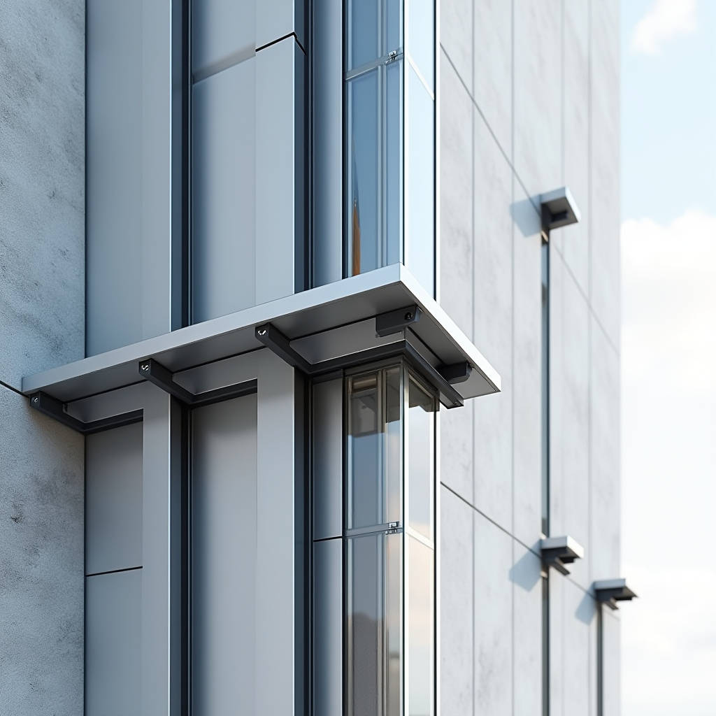
When a project team evaluates a rainscreen facade, the visible panel material gets most of the attention. Architects spend weeks selecting the right alloy, finish, and panel dimension. But the system that actually carries those panels, transfers wind loads, and determines long-term alignment sits behind the visible surface. The Aluminum Substructure is where engineering discipline meets installation reality. A poorly designed substructure can turn premium solid aluminium cladding panels into a liability. Thermal movement gets locked, fasteners corrode, and sightlines drift. This article focuses on one specific dimension of Aluminum Substructure performance that gets overlooked in early-stage budgets: the relationship between profile geometry, fastener selection, and thermal expansion accommodation across vertical spans exceeding 30 meters.
The Engineering Problem That Compound Height Creates
On a three-story building, thermal expansion in an Aluminum Substructure rarely causes visible problems. The cumulative movement stays within the tolerance that standard slotted connections can absorb. But when the facade rises past 30 meters, the math changes. A 6063-T6 aluminum profile expands at roughly 23.4 × 10⁻⁶ mm/mm/°C. On a 35-meter vertical run with a 60°C temperature swing between winter night and summer afternoon, the total linear movement approaches 49 millimeters. That movement has to go somewhere.
The common failure mode is not catastrophic collapse. It is progressive: fasteners loosen, panel joints shift unevenly, and sealant lines crack. The Aluminum Substructure itself remains intact, but the cladding panels it supports begin showing misalignment that no amount of field adjustment can fully correct. The root cause traces back to a decision made during the value-engineering phase, where fixed connection points were specified at both ends of a vertical mullion to reduce bracket count.
This is not a material problem. It is a detailing problem. Aluminum as a substructure material offers significant advantages over galvanized steel for rainscreen applications: corrosion resistance without coating dependency, lower dead load, and easier field cutting. But those advantages only materialize when the connection design respects the material's thermal behavior. The Aluminum Substructure needs room to move, and the taller the building, the more deliberate that accommodation must be.
Profile Selection: Open Sections vs. Closed Tubes
Extruded aluminum profiles for substructure fall into two broad categories: open sections, typically T-shaped or L-shaped, and closed tubular sections, rectangular or square hollow profiles. Each behaves differently under the combined demands of dead load, wind load, and thermal cycling.
Open T-sections dominate the rainscreen market because they allow direct access for fastener installation from the front. An installer can position a panel clip anywhere along the vertical leg without needing to thread bolts through a hollow section. This speeds up installation and reduces labor cost. The trade-off is torsional stiffness. An open T-profile resists bending in the strong axis well, but wind suction can twist the section if the panel attachment eccentricity is too large. For solid aluminium panels at 2.5mm or 3.0mm thickness, the panel weight is modest, typically 6.8 to 8.1 kg/m², but wind loads on corner zones can exceed 3.0 kPa on high-rise facades. The Aluminum Substructure profile must resist twisting under those suction loads without requiring excessive bracket spacing.
Closed tubular sections solve the torsion problem but introduce access complexity. Hollow profiles require either pre-slotted holes for clip attachment or a two-part connection system with a separate mounting rail. The additional components add cost, but on tall facades with high wind exposure, the closed section may be the only option that keeps bracket spacing economical. A 60mm × 40mm × 3mm rectangular hollow section in 6063-T6 can span 2.4 meters between brackets at 2.5 kPa design wind load, while an equivalent-weight T-section might need brackets at 1.8 meters. The bracket count difference across a 5,000 m² facade is substantial enough to offset the higher profile cost.
Thermal Movement: Designing the Slip Joint
The Aluminum Substructure expands and contracts along its length. The panels attached to it also expand and contract, but at potentially different rates depending on the panel material. Solid aluminium panels move at the same rate as the substructure if both are 6063 alloy, which simplifies joint design. When the panel is a different material, such as a ceramic or fiber cement panel on an aluminum substructure, differential movement must be calculated separately.
The standard approach for vertical Aluminum Substructure mullions is a fixed point at mid-span with sliding connections at both ends. This divides the total movement in half, reducing the required slot length at each bracket. On a 35-meter mullion, the fixed point at 17.5 meters means each end moves approximately 24.5 mm in the 60°C swing scenario. The bracket slot must accommodate that movement plus a safety margin, typically 30 to 35 mm of travel.
A detail that field teams often miss: the sliding connection must allow movement in the direction parallel to the mullion axis, but the bolt must be torqued to prevent rattling under wind vibration. Nylon washers between the aluminum bracket and the stainless steel bolt head reduce friction and prevent galling. Specifying a 316-grade stainless steel bolt with a nylon shoulder washer is a small line item that prevents a large call-back.
The Aluminum Substructure design should also account for the fact that panels themselves create a partial shading effect. The south-facing mullion behind a dark-colored panel will reach a higher temperature than the north-facing mullion behind a light panel. On a building with mixed panel colors, the differential expansion between adjacent mullions can be 3 to 5 mm over a 30-meter span. The horizontal joint between panels needs enough width to absorb that differential without binding.
Bracket Systems: The Load Path to Structure
Brackets connect the Aluminum Substructure to the building's primary structure, which is typically concrete, structural steel, or light-gauge steel framing. The bracket material choice matters. Aluminum brackets eliminate galvanic corrosion risk at the bracket-to-substructure interface but require careful thermal break design at the building attachment point. Stainless steel brackets avoid the thermal break requirement but introduce a galvanic couple that needs isolation.
The most common specification for rainscreen brackets is 6063-T5 or 6063-T6 aluminum with a thermal break pad at the wall attachment. The thermal break serves two functions: it reduces point thermal transmittance through the bracket, and it provides a compressible layer that accommodates minor substrate irregularities. A 5mm thick PVC or EPDM thermal break pad can reduce the bracket's psi-value from approximately 0.008 W/mK to below 0.003 W/mK, depending on the bracket geometry. On a building targeting Passive House or similar performance standards, this reduction matters.
Bracket spacing is governed by three factors: the bending capacity of the Aluminum Substructure profile, the pull-out capacity of the anchor in the substrate, and the allowable deflection under wind load. Most rainscreen specifications limit deflection to L/360 or L/500, where L is the span between brackets. For a 2.0-meter bracket spacing, L/360 allows 5.6 mm of deflection. A 6063-T6 T-profile with a section modulus of 8.5 cm³ can typically meet this at 2.0 kPa wind load, but the calculation must be verified for each project's specific profile geometry and loading.
Fastener Selection: Stainless Steel and the Galvanic Question
Every fastener in an Aluminum Substructure assembly is a potential corrosion site. Aluminum and stainless steel are close on the galvanic series, but they are not identical. In the presence of an electrolyte, typically rainwater carrying dissolved salts or pollutants, a galvanic current can flow between the stainless steel fastener and the aluminum profile. The aluminum, being less noble, corrodes sacrificially.
The practical solution is a combination of material selection and physical isolation. Fasteners should be 316-grade stainless steel, not 304, for any project within 5 kilometers of a coastline or in an industrial area with airborne pollutants. The fastener should be isolated from the aluminum with a nylon or EPDM washer at the head and, where possible, a nylon sleeve through the hole. This breaks the electrical circuit and prevents galvanic corrosion even in aggressive environments.
A less obvious concern is crevice corrosion. Where a stainless steel fastener clamps tightly against an aluminum surface, the small gap between the two materials can trap moisture and create an oxygen-depleted zone that accelerates localized corrosion. Specifying a minimum 1mm EPDM gasket between all stainless-to-aluminum contact surfaces addresses this. The gasket cost is negligible, but the remediation cost for corroded fastener holes is not.
For projects where the Aluminum Substructure is supplied by a specialist manufacturer, the fastener specification should be part of the system warranty. Futeng® and similar suppliers provide complete substructure packages with matched profiles, brackets, and fasteners, which shifts the compatibility risk from the installer to the manufacturer. This is worth the premium on complex facades where fastener failure could cascade into panel replacement.
Wind Load Distribution Across the Substructure Grid
Wind load on a rainscreen does not arrive uniformly. The building corners and edges experience higher suction pressures than the field zones. ASCE 7 and EN 1991-1-4 both define corner zones where the design wind pressure can be 2.5 to 3.0 times the field zone pressure. The Aluminum Substructure grid must be designed for the worst-case zone, or the bracket spacing must be varied across the facade.
Varying bracket spacing is the more economical approach but adds complexity to the installation drawings. A typical optimization places brackets at 1.2-meter centers in corner zones, 1.6 meters in edge zones, and 2.0 meters in field zones. The profile section remains constant, which simplifies procurement. The bracket count increases by approximately 25% compared to a uniform 2.0-meter grid, but the alternative, designing the entire facade for corner-zone loads, would require a heavier profile across all zones, increasing material cost by 30 to 40%.
The Aluminum Substructure also transfers wind load to the building structure through the brackets. Each bracket anchor point must be verified for both pull-out and shear capacity in the specific substrate material. Concrete anchors in hollow-core plank, for example, have significantly lower pull-out capacity than in solid cast-in-place concrete. A project that switches from cast-in-place to precast during value engineering may need a complete bracket anchor redesign.
Fire Performance and the Aluminum Substructure
The combustibility of aluminum is a concern in high-rise facade design, particularly in jurisdictions that have tightened regulations following facade fires. Aluminum melts at approximately 660°C, and in a fully developed compartment fire, temperatures can exceed this within minutes. The Aluminum Substructure is located behind the cladding panels, in the ventilated cavity where fire can spread vertically if not properly compartmented.
The primary fire protection strategy for aluminum substructure systems is cavity fire barriers. Horizontal fire stops, typically mineral wool with intumescent strips, are installed at each floor level to close the cavity and prevent vertical fire spread. The Aluminum Substructure mullions pass through these barriers, requiring a detail that maintains the fire rating while allowing thermal movement. A common solution is a split mullion at the fire barrier, with each segment independently supported and a movement gap sized for the expected thermal expansion of the segment length.
Some projects specify steel substructure for the fire barrier zones and aluminum for the remainder. This hybrid approach adds complexity but can satisfy fire engineering requirements without the weight penalty of a full steel system. The transition detail between aluminum and steel mullions requires a galvanic isolation break and careful alignment to maintain the panel plane.
Cost Drivers Beyond the Profile Price
The quoted price per meter for an extruded aluminum profile tells only a fraction of the cost story. Installation labor, bracket count, anchor type, and waste factor all multiply the installed cost. A profile that is 15% cheaper per meter but requires 30% more brackets due to lower spanning capacity will cost more installed.
The table below compares installed cost estimates for three common Aluminum Substructure configurations on a 2,000 m² vertical rainscreen facade with 3.0mm solid aluminium panels, based on 2024 material and labor rates in Western Europe.
| Configuration | Profile Type | Bracket Spacing | Bracket Count | Installed Cost/m² | Best Application |
|---|---|---|---|---|---|
| A | T-section 60×40×3mm | 2.0m uniform | 1,250 | €42–€48 | Low-rise, low wind exposure |
| B | T-section 80×50×3mm | 1.6m edge / 2.0m field | 1,560 | €51–€58 | Mid-rise, moderate wind |
| C | RHS 60×40×3mm | 1.2m corner / 1.6m edge / 2.0m field | 1,980 | €58–€66 | High-rise, high wind, corner zones |
Configuration C costs roughly 35% more per square meter than Configuration A, but on a 35-meter tower in an exposed location, Configuration A would fail the deflection criteria at corner zones. The cost difference is not optional; it is the price of engineering adequacy. The Aluminum Substructure specification must be driven by structural calculations, not by a target cost per square meter set before wind loads are known.
Quality Control in Extrusion and Fabrication
The Aluminum Substructure begins its life as an extrusion billet, typically 6063 or 6060 alloy, heated to around 500°C and forced through a die. The extrusion process introduces residual stresses that can cause the profile to warp during subsequent machining or thermal cycling. A reputable extruder will perform a T5 or T6 heat treatment after extrusion to relieve these stresses and achieve the specified mechanical properties.
Dimensional tolerance on extruded aluminum profiles is governed by EN 755-9 or the Aluminum Association's ANSI H35.2 standards. For a typical 60mm deep T-section, the tolerance on the cross-sectional dimensions is approximately ±0.3mm to ±0.5mm, depending on the dimension. This is tight enough for most rainscreen applications, but accumulated tolerances across multiple profiles can create alignment issues if the bracket slots do not have enough adjustment range.
Fabrication steps after extrusion include cutting to length, drilling or punching fastener holes, and applying a protective finish. Most Aluminum Substructure profiles receive a black powder coating, typically 60 to 80 microns thick, for corrosion protection and a uniform appearance behind open-joint cladding. The powder coating should meet Qualicoat Class 2 or AAMA 2604 specifications for exterior architectural applications. For coastal or industrial environments, Qualicoat Class 3 or AAMA 2605 seaside-grade coating is recommended.
Field cutting of powder-coated profiles exposes bare aluminum at the cut edge. This edge will form a natural oxide layer and is generally acceptable in non-coastal environments. Within 5 kilometers of salt water, cut edges should be treated with a cold galvanizing compound or zinc-rich paint to provide sacrificial protection. This is a small step that is often skipped on site, and the resulting corrosion shows up two to three years later.
Installation Sequence and Tolerance Stack-Up
The Aluminum Substructure is the reference plane for the entire facade. If it is installed out of plane by 5mm, the panels will be out of plane by 5mm, and no amount of panel adjustment can fix a crooked substructure. The installation sequence should start with establishing a datum line at each floor level using a laser level. Brackets are installed to this datum, not to the concrete edge, which may have its own deviations.
Bracket adjustment is typically provided by slotted holes in the bracket base, allowing 20 to 30mm of in-out adjustment to accommodate substrate irregularities. After the brackets are aligned, the vertical mullions are hung, and the horizontal rails are attached. The panel clips are the last component installed, and they provide the final 5 to 10mm of adjustment in the plane of the panel.
A common sequencing error is to fully tighten all bracket bolts before the mullions are aligned. This locks in any misalignment. The correct sequence is to snug-tighten the brackets, align the mullions with a straightedge across multiple brackets, and then torque the bolts to specification. On a 35-meter facade, this alignment process can take a full day for a crew of four, but it determines the visual quality of the finished facade.
The Aluminum Substructure must also accommodate the dead load of the panels without creep. Aluminum does not creep at ambient temperatures, unlike some thermoplastics used in older cladding systems. The elastic deflection under panel weight is immediate and recovers when the load is removed. This means the substructure alignment set during installation will remain stable over the building's service life, provided the connections do not loosen.
Maintenance Access and Long-Term Serviceability
A rainscreen facade with an Aluminum Substructure is designed for a service life of 30 to 50 years with minimal maintenance. The panels may need cleaning, and sealant joints may need replacement, but the substructure itself should not require intervention. The exception is fastener inspection. On buildings over 30 meters, access for periodic inspection of the bracket connections should be considered during the design phase.
Some system designs allow individual panels to be removed from the front without disturbing adjacent panels. This requires a clip system that can be disengaged with a specialized tool, and it requires the Aluminum Substructure to be designed with enough clearance behind the panel for the tool to operate. A 40mm cavity depth is typical for tool access. If the cavity is reduced to 25mm for thermal performance reasons, front-access panel removal may not be possible, and maintenance access must be planned from the building interior or via a suspended platform.
The choice between front-access and fixed-panel systems affects the Aluminum Substructure design. Front-access systems require clips that are mechanically fastened to the substructure rather than bonded, and the fastener locations must be accessible. Fixed-panel systems can use simpler, lower-cost clips but make individual panel replacement significantly more difficult. The decision should be documented in the project's maintenance plan, not left to the installer to figure out later.
Specifying the Aluminum Substructure: Key Contract Points
The specification for the Aluminum Substructure should be a standalone section in the project documentation, not buried in the cladding specification. It should reference the specific alloy (6063-T6 or 6060-T6), the extrusion tolerance standard, the coating specification, and the fastener grade. The structural calculations should be submitted as part of the shop drawing package, and they should cover the specific bracket spacing, profile section, and wind load zones for the project.
Performance testing of the complete system, including panels, substructure, and brackets, should follow AAMA 501 or CWCT standards for rainscreen systems. The test sequence typically includes air permeability, water penetration under static pressure, and wind resistance under cyclic loading. These tests expose weaknesses in the substructure design that calculations alone might miss, such as fastener loosening under cyclic wind loads.
For projects specifying solid aluminium panels on an Aluminum Substructure from a single supplier, the warranty should cover the complete system, including the substructure, brackets, fasteners, and panels. This avoids the situation where the panel supplier blames the substructure installer for alignment problems, and the installer blames the panel supplier for dimensional issues. A single-source warranty from a manufacturer like Futeng® simplifies this chain of responsibility.
The Aluminum Substructure is the skeleton of the rainscreen system. It determines whether the facade performs as a weather barrier, whether it remains visually aligned over decades, and whether it survives the wind loads that the building will face. The engineering decisions made during the substructure design phase, profile selection, bracket spacing, fastener specification, thermal movement accommodation, are not adjustable after the panels go on. They are locked in, visible or not, for the life of the building.