Aluminum Sub Frame System Engineering Load Paths Thermal Breaks and Corrosion Control
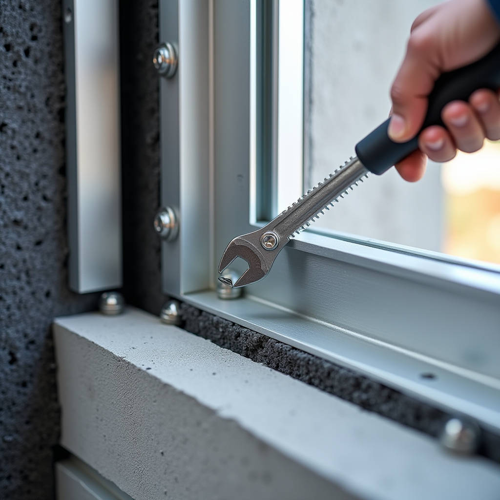
When a rainscreen facade fails, the post-mortem rarely points to the cladding panel itself. The aluminium sheet—2.5mm thick, PVDF-coated, fabricated to millimeter tolerance—is almost never the culprit. The failure lives behind the visible surface, in the grid of brackets, rails, and fasteners that connects the decorative skin to the structural backup wall. This is the domain of the Aluminum Sub Frame System, and getting it wrong means panels that warp under thermal load, fasteners that corrode within five years, and a rainscreen cavity that no longer drains. The subframe is not a commodity extrusion. It is a load-path, a thermal break, a drainage plane, and a corrosion cell boundary all operating simultaneously. This article examines the specific engineering decisions that separate a subframe that performs for three decades from one that generates callbacks in three years.
What an Aluminum Sub Frame System Actually Does
An Aluminum Sub Frame System performs four distinct structural and environmental functions that are often conflated in specification writing. First, it transfers dead load—the weight of solid aluminium panels, typically 7.0 to 8.5 kg/m² for 3.0mm sheet—back to the primary structure through a series of brackets and vertical rails. Second, it accommodates differential movement between the cladding skin and the building frame. A 6000mm aluminium panel on a south-facing elevation can expand 3.0 to 4.5mm over a diurnal cycle, and the subframe must absorb this without transferring stress into the panel fasteners. Third, it defines the rainscreen cavity depth—typically 38mm to 50mm for ventilated systems—and maintains this dimension across the entire elevation regardless of substrate irregularities. Fourth, it creates the attachment plane for the panels themselves, which means the subframe's flatness tolerance directly determines the visual flatness of the finished facade.
These functions are not independent. A bracket that provides excellent dead-load capacity but poor thermal isolation will create a cold bridge that condenses moisture inside the cavity. A rail system that adjusts easily on site but relies on bi-metallic contact between aluminium and galvanized steel will corrode within a decade. The engineering challenge is that optimizing for one function often compromises another, and the compromises are not always obvious at the specification stage.
Load Path Design: Why Bracket Spacing Is Not a Catalogue Number
Manufacturers publish load tables showing maximum allowable bracket spacing for their subframe profiles. These tables are calculated under controlled conditions—uniformly distributed load, simply supported spans, static loading only. Real buildings do not cooperate. Wind loads vary dramatically across an elevation, with corner zones experiencing suction pressures 2.0 to 2.5 times higher than field zones per ASCE 7 provisions. A subframe spaced at 1200mm centers in the field zone may need to drop to 800mm or even 600mm at corners, parapets, and roof edges.
The load path also changes depending on panel orientation. Vertical panels hung on horizontal rails transfer load differently than horizontal panels on vertical rails. In the vertical orientation, the panel's self-weight bears on the bottom rail through bearing clips, while wind load is resisted by the full rail grid. In the horizontal orientation, each panel row bears on its own rail pair, and the vertical mullions carry the cumulative weight of all panels above. This second configuration requires careful checking of mullion buckling at lower floors, where the accumulated dead load from 20 or 30 floors of solid aluminium panels can become significant.
Wind load calculations should reference the project-specific wind tunnel study or, at minimum, the local building code's prescribed pressure coefficients. A generic assumption of 1.0 kPa serviceability wind load is inadequate for buildings over 30 meters in height or those in coastal typhoon zones. For a 100-meter tower in a Category 3 hurricane region, design wind pressures can exceed 3.5 kPa at corners, and the subframe brackets must resist this load with a safety factor of 2.0 or greater against ultimate failure.
Thermal Bridging and the Condensation Problem
The rainscreen cavity is supposed to be a dry, ventilated space. When an Aluminum Sub Frame System creates thermal bridges through the insulation layer, the cavity becomes a condensation chamber. Aluminium has a thermal conductivity of approximately 160 W/m·K—roughly 1,000 times higher than mineral wool insulation. Every bracket that penetrates the insulation layer creates a localized cold spot on the interior face of the cavity. When warm, moist interior air reaches this cold surface, condensation forms.
The solution is thermal isolation at the bracket-to-substrate connection. Thermally broken brackets incorporate a polyamide or rigid PVC isolator pad—typically 8mm to 12mm thick—between the aluminium bracket and the concrete or steel substrate. This pad reduces the thermal bridge by a factor of 200 to 400, depending on material and thickness. The thermal performance improvement is measurable: a non-isolated bracket might show a surface temperature 12°C to 15°C below ambient at the connection point, while an isolated bracket maintains a temperature within 2°C to 3°C of ambient.
Specifiers should require thermal break pads with a thermal conductivity below 0.30 W/m·K and a compressive strength sufficient to carry the bracket load without creep. Polyamide 6.6 with 25% glass fiber reinforcement is a common choice, offering compressive strength above 100 MPa and thermal conductivity around 0.25 W/m·K. The pad thickness should be verified against the project's climate zone, with colder climates requiring thicker isolators. Projects in ASHRAE Climate Zone 6 and above should consider 12mm pads as a minimum.
Corrosion Compatibility: The Galvanic Series in Practice
Aluminium sits near the anodic end of the galvanic series. When it contacts more noble metals—stainless steel, copper, brass—in the presence of an electrolyte, the aluminium corrodes sacrificially. This is well understood in principle but frequently mishandled in practice. The most common error is using zinc-plated steel fasteners to connect aluminium brackets to aluminium rails. Zinc is close enough to aluminium on the galvanic series that corrosion is slow in dry conditions, but the rainscreen cavity is not dry. It is a ventilated exterior environment subject to humidity, condensation, and occasional wind-driven rain.
The correct fastener for aluminium-to-aluminium connections in a rainscreen cavity is A2 or A4 stainless steel (304 or 316 grade per ASTM F593). Stainless steel is cathodic to aluminium, but the small cathode-to-anode area ratio—a stainless fastener head against a large aluminium rail—limits the galvanic current to negligible levels. The dangerous configuration is the reverse: aluminium fasteners in a stainless or copper component, where the large cathode area drives rapid corrosion of the small aluminium anode.
For coastal and marine environments, 316 stainless fasteners are mandatory. The molybdenum content in 316 provides resistance to chloride-induced pitting that 304 cannot match. Projects within 5 kilometers of a saltwater coast should specify 316 for all subframe fasteners, brackets, and any exposed metal components. The cost premium is typically 10% to 15% over 304, which is negligible compared to the cost of replacing corroded subframe components behind an installed facade.
Adjustability and Site Tolerance
Concrete structures are not built to millimeter accuracy. A cast-in-place concrete slab can deviate from its design plane by ±15mm over a 3-meter span, and the cumulative deviation across a 30-meter elevation can exceed 50mm. The Aluminum Sub Frame System must absorb these deviations while delivering a panel mounting plane that is flat to within 3mm over 3 meters—the typical tolerance required for visually acceptable solid aluminium cladding.
Three-axis adjustability is the standard for professional subframe systems. The bracket-to-substrate connection provides in-out adjustment (Z-axis) typically ranging from 70mm to 250mm, accommodating both the insulation thickness and the substrate irregularity. The bracket-to-rail connection provides vertical adjustment (Y-axis) through slotted holes, typically ±15mm. The rail itself provides horizontal adjustment (X-axis) through the continuous slot that accepts panel clips at any position along its length.
The critical detail is the locking mechanism at each adjustment point. Serrated contact surfaces—machined grooves on both the bracket and the rail that interlock when tightened—prevent slippage under load. Without serrations, the friction-only connection can creep over time, especially under cyclic thermal loading. A serrated connection with a bolt torque of 25 N·m to 30 N·m on an M8 stainless fastener will maintain its position indefinitely. The serration pitch should be 1.0mm or finer to provide adequate adjustment resolution.
Fire Performance and NFPA 285 Compliance
For buildings over 12 meters in height in North America, the NFPA 285 standard requires that the entire exterior wall assembly—including the subframe—pass a full-scale fire propagation test. Aluminium subframes are inherently non-combustible, which satisfies the base material requirement. However, the thermal break pads, gaskets, and any polymeric components within the subframe assembly must also be evaluated for their contribution to fire propagation.
The polyamide thermal break pads discussed earlier are combustible. They will melt and burn under the 540°C temperatures reached in an NFPA 285 test. The question is whether they contribute to flame propagation beyond the test limits. Most 25% glass-filled polyamide 6.6 pads pass NFPA 285 when used in the standard configuration, but the specific assembly must be tested. A subframe system that passed with 8mm pads may not pass with 15mm pads, because the larger combustible mass changes the fire dynamics.
Specifiers should request the full NFPA 285 test report for the specific subframe configuration being used, not a generic letter of compliance. The test report should list the exact bracket type, pad material and thickness, rail profile, insulation type and thickness, and cladding panel material. Any deviation from the tested configuration requires engineering judgment about whether the change is conservative or requires retesting.
Material Specifications: 6063 T6 and What the Temper Means
Most aluminium subframe extrusions are specified as 6063 T6 alloy per ASTM B221. The "6063" designates the alloy composition—approximately 0.4% silicon, 0.7% magnesium, balance aluminium—which provides good extrudability and adequate strength. The "T6" designates the temper: solution heat-treated and artificially aged to peak strength. 6063 T6 delivers a minimum tensile strength of 205 MPa and a minimum yield strength of 170 MPa.
Some manufacturers offer 6061 T6 as an upgrade. 6061 T6 provides higher strength—minimum tensile of 290 MPa and yield of 240 MPa—at the cost of slightly reduced extrudability and a 10% to 15% price premium. For most rainscreen applications, 6063 T6 is adequate. The higher strength of 6061 becomes relevant when bracket spans exceed 1500mm, when panels are unusually heavy (stone veneers, terracotta), or in high-seismic zones where the subframe must resist both wind and inertial loads simultaneously.
The wall thickness of the extrusion matters as much as the alloy. A 2.0mm wall thickness on a 50mm × 50mm rail provides adequate bending strength for most applications, but the connection points—where bolts bear against the extrusion wall—may require localized thickening or the use of toothed washers to prevent pull-through. Extrusions thinner than 1.5mm should be approached with caution for any load-bearing subframe component.
Drainage and Ventilation: The Cavity as a System
The rainscreen cavity is not a passive gap. It is an engineered ventilation channel that must equalize pressure while draining any water that penetrates the outer skin. The subframe directly affects both functions. Vertical rails that run continuously from floor to floor can block horizontal airflow, creating dead zones where moisture accumulates. The solution is either to use discontinuous rails with gaps at each floor level, or to specify rails with punched ventilation openings at regular intervals.
The cavity width—measured from the back of the cladding panel to the face of the insulation—should be a minimum of 38mm for ventilated systems and 50mm for drained-and-ventilated systems in high-rainfall climates. The subframe bracket depth must be selected to achieve this dimension after accounting for substrate irregularities. A bracket with 100mm of adjustment range does not guarantee a 50mm cavity if the concrete slab bows inward by 40mm at mid-span. The bracket must be set to 90mm at that location to maintain the cavity, and this requires the installer to survey the substrate and set each bracket individually.
At the base of the cavity, a continuous drainage profile collects water and directs it out through weep holes. This profile is part of the subframe system and must be detailed to prevent water from tracking back into the building at the floor line. A 15mm vertical leg on the drainage profile, turned up against the back of the cavity, provides a capillary break that stops water from migrating horizontally.
Comparative Analysis of Subframe Configurations
The choice between vertical rail, horizontal rail, and grid-based subframe systems affects cost, installation speed, thermal performance, and the visual options available for panel layout. The table below summarizes the key trade-offs for solid aluminium cladding applications.
| Subframe Configuration | Typical Rail Spacing | Installation Speed | Thermal Performance | Best Application |
|---|---|---|---|---|
| Vertical rail only | 600-900mm c/c | Fast (fewer components) | Moderate (continuous rails bridge floors) | Vertical panel orientation, simple geometry |
| Horizontal rail only | 800-1200mm c/c | Moderate | Good (rails can be discontinuous at floors) | Horizontal panel orientation, running bond patterns |
| Grid system (vertical + horizontal) | 1200×1200mm typical | Slow (most components) | Best (thermal breaks at all connections) | Large-format panels, complex geometries, high wind zones |
| Cassette carrier system | Panel width dependent | Fastest (pre-assembled units) | Good (minimal penetrations) | Unitized facade, high-rise, repeatable panel sizes |
The grid system, while the most expensive in material and labor, provides the most flexibility for panel layout and the best thermal performance. It is the default choice for premium commercial projects where the facade is a significant architectural statement. The vertical-rail-only system is appropriate for industrial and logistics buildings where cost and speed dominate, and the thermal performance requirements are less stringent.
Supply Chain Considerations for International Projects
International projects sourcing subframe components from overseas manufacturers face specific challenges. Extrusion die availability, lead times, and minimum order quantities vary significantly between suppliers. A custom subframe profile requires a new extrusion die, which costs $2,000 to $5,000 and takes 3 to 4 weeks to produce. Standard profiles—50mm × 50mm × 3mm angle, 40mm × 80mm channel—are typically available from stock.
Surface finish on subframe components is often overlooked. Mill-finish aluminium is the default for subframe extrusions because they are hidden behind the cladding. However, in coastal environments, mill-finish aluminium will develop white corrosion products within 12 to 18 months. Anodizing to AA-M10C22A31 (clear anodize, 15 microns minimum) or AA-M10C22A41 (20 microns) provides adequate protection for hidden components in marine environments. The cost adder is approximately $0.80 to $1.20 per kilogram of extrusion.
For projects requiring large quantities of custom subframe components, working with a manufacturer that controls both extrusion and fabrication under one roof reduces coordination risk. Futeng® is one such supplier, offering solid aluminium panels and compatible subframe systems from a single production facility, which eliminates the finger-pointing that occurs when the panel supplier and subframe supplier blame each other for fit-up problems.
Installation Sequence and Quality Control
The subframe installation sequence determines the accuracy of the finished facade. The correct sequence is: survey the substrate, set the bracket positions, install brackets with thermal break pads, verify bracket plane, install vertical rails, verify rail plane, install horizontal rails (if grid system), verify grid plane, then begin panel installation. Each verification step should be documented with a laser survey or total station measurement, not a string line.
The most common installation error is failing to set brackets to the correct plane before installing rails. Installers often set brackets to a uniform projection from the substrate, which replicates the substrate's irregularities in the rail plane. The correct method is to set each bracket individually to achieve a common plane, using the bracket's adjustment range to compensate for substrate deviations. This takes longer—perhaps 30% more labor for the bracket-setting phase—but eliminates the need to shim panels later, which is far more time-consuming.
Bolt torque verification is the second critical quality control point. Under-torqued bolts allow slippage; over-torqued bolts can strip threads or deform the extrusion. A calibrated torque wrench set to the manufacturer's specification—typically 25 N·m to 30 N·m for M8 stainless bolts in aluminium—should be used for every connection. On large projects, a sample of 5% of connections should be checked with a torque audit wrench, and the results documented.
When to Replace Rather Than Repair
Existing buildings with failing subframe systems present a difficult decision. Corroded brackets, sagging rails, and panels that have shifted out of plane are all symptoms of subframe failure. In some cases, individual components can be replaced by removing the affected panels and installing new brackets and rails. In other cases, the corrosion or deformation is systemic, and a full subframe replacement is the only durable solution.
The decision hinges on the extent of corrosion. If more than 15% of brackets show visible corrosion products—white powder on aluminium, red rust on steel components—the system is likely compromised beyond economical repair. The cost of replacing individual brackets behind an installed facade, including panel removal and reinstallation, typically runs $120 to $200 per bracket, which quickly exceeds the cost of a full strip-and-replace when many brackets are affected.
A full replacement also provides the opportunity to upgrade the subframe to current standards. Older systems may lack thermal breaks, use incompatible fasteners, or have inadequate adjustability. The incremental cost of upgrading to a modern, thermally broken, fully adjustable Aluminum Sub Frame System during a replacement project is modest compared to the total project cost, and the performance improvement is permanent.
The subframe is not the part of the facade that anyone sees. It is the part that determines whether the visible surface stays flat, stays dry, and stays attached for the life of the building. Engineering it properly means treating it as a system, not a collection of extrusions. The loads, the thermal paths, the corrosion cells, and the installation tolerances all interact. A subframe that handles each interaction correctly will outlast the panels it supports.