Aluminum Angle Bracket Engineering for Solid Aluminium Cladding Facade Systems
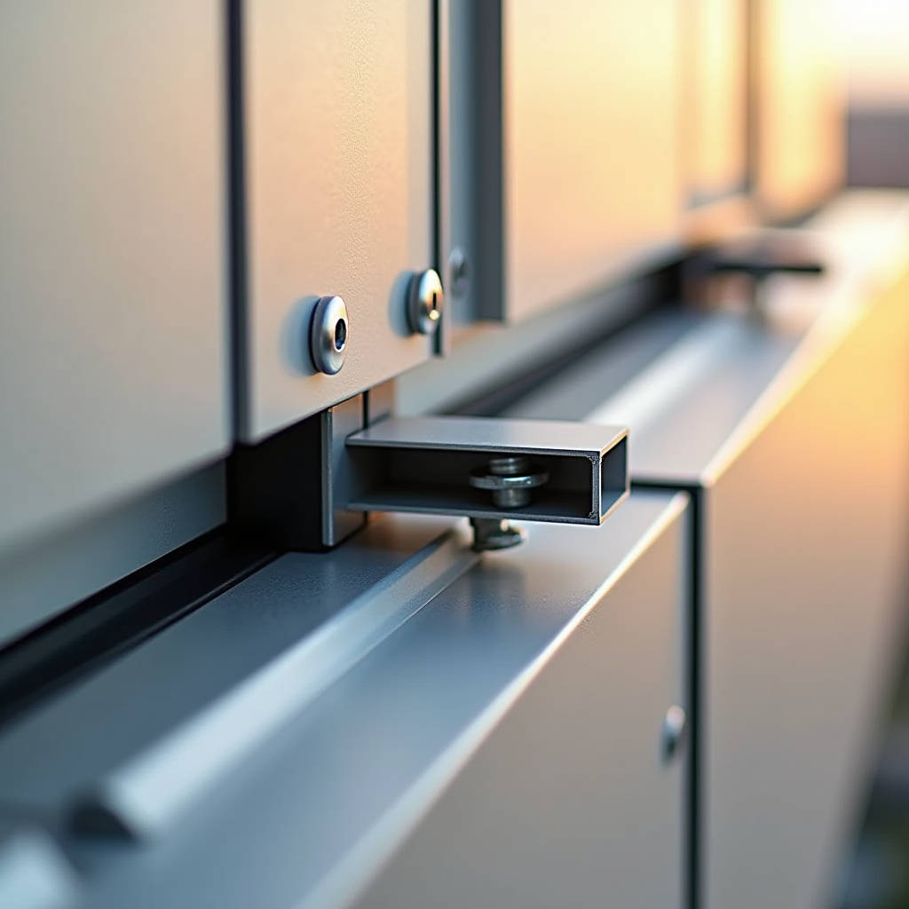
When a curtain wall contractor faces a 40-story tower with 22,000 square meters of solid aluminium cladding, the conversation rarely starts with the panels themselves. It starts with the connections. The substructure. The components that transfer wind loads from the facade skin back to the building frame. And at the heart of that load path sits the Aluminum Angle Bracket — a deceptively simple piece of extruded or fabricated aluminium that determines whether a rainscreen performs for 30 years or becomes a maintenance liability in five. This article examines how bracket alloy selection, geometry, and interface design directly govern the long-term structural performance of solid aluminium cladding systems, with particular attention to thermal movement accommodation, galvanic corrosion prevention, and the cost implications of specifying brackets that match the service life of the panels they support.
Why the Aluminum Angle Bracket Deserves More Engineering Attention Than It Gets
Most project specifications run to 40 pages on panel flatness, PVDF coating thickness, and alloy temper. The brackets get two lines. This is backwards. A solid aluminium panel — 2.5mm or 3.0mm thick, 5052 or 3003 alloy, finished with a 70/30 PVDF system — has a service life that can reach 40 years when properly detailed. The Aluminum Angle Bracket that connects that panel to the vertical rail or horizontal girt needs to match that timeline. If the bracket corrodes, creeps, or fractures, the panel is compromised regardless of how well the coating holds up.
The typical failure modes are well documented among forensic engineers: stress corrosion cracking at the bracket-to-rail interface, galvanic pitting where a carbon steel fastener contacts the aluminium bracket, and fatigue fractures at the bend radius of fabricated angles subjected to cyclic wind loading. Each of these failures traces back to decisions made during the shop drawing phase — decisions that are often delegated to the lowest-cost fabricator without meaningful engineering review.
Alloy Selection: Not All 6000 Series Is the Same
Walk through any aluminium extrusion plant and you will hear "6063 is fine for brackets." Sometimes it is. Sometimes it is not. The distinction matters when the bracket carries structural loads in a marine or industrial atmosphere.
6063-T6 offers good extrudability and a smooth surface finish that takes anodizing well. Its yield strength runs around 170 MPa, which is adequate for most low-rise and mid-rise applications where bracket spans are short and wind loads are moderate. But when the project is a coastal high-rise with design wind pressures exceeding 2.5 kPa, the math changes. 6061-T6, with a yield strength of approximately 240 MPa, provides a 40% increase in load-bearing capacity. For a bracket that is already constrained by cavity depth and architectural sightlines, that extra strength means the difference between a standard section and a custom extrusion — or worse, a bracket that yields under a 50-year storm.
There is also the question of 5083 alloy for brackets in extreme marine environments. While 5083 is more commonly associated with solid aluminium cladding panels themselves (particularly for projects within 5 km of saltwater coastlines), some engineers are now specifying 5083-H116 for brackets in these same conditions. The magnesium content in 5083 provides superior resistance to chloride-induced pitting compared to the 6000 series. The trade-off is cost and availability: 5083 angle stock is less common and typically requires fabrication from plate rather than extrusion, adding 15-25% to the bracket cost.
Fabricated vs. Extruded Brackets: A Cost-Performance Decision
An Aluminum Angle Bracket can be produced two ways: extruded directly to the required profile, or fabricated by bending aluminium sheet or plate. The choice affects everything from corner radius to fatigue life.
Extruded brackets have a consistent cross-section with a controlled internal radius at the corner. That radius — typically 2-4 mm depending on the die design — distributes stress more evenly than the sharp inside corner of a bent bracket. For projects in high-seismic zones or regions with significant diurnal temperature swings, that radius matters. A bent bracket with a sharp internal corner concentrates stress at that point. Under repeated thermal cycling — where a 3-meter panel can expand and contract by 2-3 mm over a 24-hour period — that stress concentration becomes a crack initiation site.
Fabricated brackets, however, offer flexibility. A fabricator can produce custom angles with non-standard leg lengths, multiple bolt slots, or folded stiffening ribs without the upfront tooling cost of an extrusion die. For small projects under 2,000 square meters, fabricated brackets are often the economical choice. The key is specifying a minimum bend radius: at least 1.5 times the material thickness for 6061-T6, and preferably 2 times for 5052-H32. Anything tighter invites micro-cracking at the bend line.
| Parameter | Extruded 6063-T6 Bracket | Extruded 6061-T6 Bracket | Fabricated 5052-H32 Bracket | Fabricated 6061-T6 Bracket |
|---|---|---|---|---|
| Yield Strength (MPa) | 170 | 240 | 195 | 240 |
| Corrosion Resistance (Marine) | Moderate | Moderate | Excellent | Moderate |
| Typical Bend Radius (min) | N/A (die-controlled) | N/A (die-controlled) | 2.0t | 1.5t |
| Tooling Cost (USD) | 800-1,500 | 800-1,500 | None | None |
| Relative Unit Cost | Low | Medium | Medium | Medium-High |
| Fatigue Life (Cyclic Wind) | Good | Excellent | Moderate | Good |
| Lead Time (Typical) | 3-4 weeks | 3-4 weeks | 1-2 weeks | 1-2 weeks |
Thermal Movement: The Silent Load Case
Wind loads get the attention. Thermal loads do the damage. A solid aluminium panel with a coefficient of thermal expansion of approximately 24 × 10⁻⁶ /°C will expand by roughly 2.4 mm per meter over a 100°C temperature range. In Dubai, where surface temperatures on a dark PVDF-coated panel can swing from 15°C at night to 85°C under direct sun, a 3-meter panel moves 5 mm every day. The Aluminum Angle Bracket must accommodate this movement without transferring the load into the fasteners or the substructure.
The standard solution is a combination of fixed points and sliding points. Fixed brackets locate the panel and transfer wind loads. Sliding brackets — typically with slotted holes oriented in the direction of expansion — allow the panel to move freely. The slot length must account for the full thermal range plus installation tolerance. A common specification error is undersizing the slot: a 10 mm slot for a 3-meter panel in a high-temperature climate is marginal. The calculation should assume worst-case temperature differentials and add 3 mm of installation tolerance per side.
The slot orientation itself is a frequent source of field problems. On a typical rectangular panel, the fixed point is at the center of the top edge. The sliding points at the bottom corners must have vertical slots. The sliding points at the top corners must have horizontal slots. Mixing these orientations — which happens more often than most contractors would admit — locks the panel and forces it to buckle. The resulting oil-canning is not a panel defect. It is a bracket detailing error.
Galvanic Corrosion: The Fastener-Bracket Interface
An Aluminum Angle Bracket attached to an aluminium rail with a stainless steel bolt creates a galvanic cell. Aluminium is the anode. Stainless steel is the cathode. In the presence of an electrolyte — rainwater, condensation, or coastal spray — the aluminium corrodes preferentially. The rate depends on the surface area ratio: a large aluminium bracket with a small stainless fastener corrodes slowly. A small aluminium bracket with a large stainless washer corrodes faster.
The standard mitigation is isolation. A nylon washer or a PTFE-coated bushing between the stainless fastener and the aluminium bracket breaks the electrical circuit. This is not optional in marine environments. The AAMA 609.1 standard for cleaning and maintenance of architectural anodized aluminium recommends isolation of dissimilar metals, and the ASTM B117 salt spray test provides a benchmark for evaluating the effectiveness of isolation strategies.
An alternative approach is to use aluminium fasteners — 2024-T4 or 7075-T6 — which eliminate the galvanic couple entirely. The trade-off is strength: aluminium fasteners have lower tensile and shear capacities than their stainless counterparts. For high-load brackets, the engineering solution is typically a stainless bolt with a robust isolation system rather than an aluminium bolt pushed beyond its capacity.
Load Path Analysis: From Panel Face to Building Frame
Wind striking a solid aluminium cladding panel generates a pressure distribution that is rarely uniform. Peak suction occurs at panel corners and edges, where the pressure coefficient can be 2-3 times higher than the center-of-panel value. The Aluminum Angle Bracket nearest the corner carries a disproportionate share of the load. A proper load path analysis traces that force through four interfaces:
- Panel to bracket: Typically a rivet or screw connection. The fastener spacing and edge distance must comply with the aluminium design manual for the specific alloy. For 5052-H32 panels, minimum edge distance is 2.0 times the fastener diameter.
- Bracket body: The bracket itself must resist bending and shear. The critical section is usually at the bend line or at the first bolt hole, where the net section is reduced.
- Bracket to rail: This is the bolted connection that transfers load from the bracket to the vertical or horizontal rail. Bolt shear capacity and bearing capacity of the aluminium bracket at the bolt hole must both be checked.
- Rail to building frame: The final interface, typically a welded or bolted connection to the primary structure.
Each interface introduces a potential failure mode. A bracket that is strong enough in bending may fail in bearing at the bolt hole. A bracket that is adequate for the panel it supports may overload the rail if the rail spacing was designed for lighter panels. The system-level thinking is what separates a properly engineered facade from one that becomes a case study in failure analysis.
Anodizing vs. PVDF Coating for Brackets
Brackets are hidden in the cavity. They are not visible from the street. The temptation is to specify the cheapest corrosion protection that meets the minimum requirement. This logic works for interior applications. It fails for exterior cladding in aggressive environments.
Anodized brackets — typically Class I anodizing per AAMA 611 — provide a hard, durable oxide layer that resists abrasion and has good UV stability. The coating thickness ranges from 15 to 20 microns. For inland applications with low pollution levels, anodized brackets perform adequately. But anodizing is porous at the microscopic level. In coastal or industrial atmospheres, chlorides or sulfur compounds penetrate the pores and attack the base metal. The result is filiform corrosion — worm-like trails that propagate under the anodic layer and eventually compromise the bracket section.
PVDF-coated brackets use the same fluoropolymer technology as the panels themselves. A 70/30 PVDF system with a minimum 25-micron dry film thickness provides a non-porous barrier that resists chloride penetration far better than anodizing. The cost premium is approximately 20-30%, but for projects within 5 km of a coastline or in heavy industrial zones, the life-cycle cost favors PVDF. Some manufacturers, including Futeng®, offer PVDF-coated brackets as a standard option for marine-grade projects, matching the bracket coating to the panel coating for a fully integrated corrosion protection system.
Seismic Considerations: Ductility and Connection Detailing
In seismic design categories D and above, the Aluminum Angle Bracket must do more than resist wind loads. It must accommodate inter-story drift without fracturing. The typical approach is to provide slotted connections that allow the panel to move relative to the substructure during a seismic event. The slot length is calculated based on the design story drift, typically 2-3% of story height for high-seismic zones.
The bracket material selection shifts in seismic applications. 6061-T6, with its higher strength, also has lower ductility than 6063-T5. A bracket that is optimized for strength may be too brittle for seismic loading. The solution is often a 6063-T6 bracket with a thicker section — trading some of the strength advantage of 6061 for the ductility of 6063. The Aluminum Association's design manual provides elongation values for each temper: 6063-T6 typically shows 8% elongation, while 6061-T6 shows 10%. The higher elongation of 6061-T6 actually makes it the better choice for seismic applications in many cases, contrary to the common assumption that higher strength means lower ductility.
Quality Control: What to Inspect Before Installation
A bracket that looks right on the shop drawing can be wrong in the field. The inspection checklist for Aluminum Angle Bracket deliveries should cover at least these points:
- Alloy verification: Request mill test reports for each batch. Verify the alloy and temper against the specification. A 6063 bracket delivered as 6061 is a problem. The reverse is also true if the design assumed 6063's extrudability for a complex profile.
- Dimensional check: Measure leg length, thickness, and hole positions on a sample from each batch. Hole position tolerance should be ±0.5 mm for bolt holes and ±1.0 mm for slotted holes.
- Coating thickness: For anodized brackets, verify coating thickness with an eddy-current gauge. For PVDF-coated brackets, use a DFT gauge and check at least three points per bracket.
- Bend radius inspection: For fabricated brackets, check the internal bend radius with a radius gauge. A radius that is too tight indicates a potential crack initiation site.
- Slot orientation: Verify that fixed and sliding brackets are correctly identified and that slot orientations match the shop drawing requirements for each panel location.
Cost Drivers: Understanding the Real Economics
The unit cost of an Aluminum Angle Bracket — typically $2 to $8 per piece depending on size, alloy, and finish — is a small fraction of the total cladding system cost. But the cost impact of bracket-related failures is enormous. Replacing a single bracket on a completed building requires removing the adjacent panels, which means labor, access equipment, and the risk of damaging panels that are no longer in production. A $5 bracket can generate a $500 repair bill.
The economic analysis should therefore consider total cost of ownership, not unit price. A PVDF-coated 6061-T6 bracket with stainless steel fasteners and isolation washers might cost $6.50 per unit. An anodized 6063-T5 bracket with zinc-plated fasteners might cost $3.80. On a 10,000-square-meter project with brackets at 600 mm centers, that difference is approximately $15,000. Spread over the 30-year service life of the facade, the premium is $500 per year — less than the cost of a single maintenance visit to inspect and replace corroded brackets.
The bracket is the cheapest component in the cladding system and the most expensive one to replace. Spend the money at the extrusion plant, not on the swing stage.
Specifying Brackets for Solid Aluminium Cladding: A Practical Framework
Drawing on the ISO 12944 corrosion classification system and the engineering principles discussed above, the following framework provides a starting point for bracket specification:
- C1-C2 (Low corrosion): Inland, rural, low humidity. 6063-T6 extruded brackets, Class I anodizing, standard fasteners with isolation washers. Minimum bracket thickness 3.0 mm.
- C3 (Medium corrosion): Urban, light industrial, moderate humidity. 6061-T6 extruded or fabricated brackets, Class I anodizing or PVDF coating. Stainless steel fasteners with isolation. Minimum bracket thickness 3.0 mm.
- C4 (High corrosion): Coastal (1-5 km), heavy industrial. 6061-T6 or 5052-H32, PVDF coating mandatory. 316 stainless fasteners with PTFE isolation. Minimum bracket thickness 4.0 mm.
- C5-M (Very high marine): Coastal (less than 1 km), offshore. 5083-H116 or 6061-T6 with PVDF. 316 stainless fasteners with full isolation system. Minimum bracket thickness 4.0 mm. Consider aluminium fasteners to eliminate galvanic couple.
This framework is a starting point, not a substitute for project-specific engineering analysis. Wind loads, seismic requirements, panel dimensions, and architectural constraints all influence the final specification. The key principle is that the bracket specification should be developed alongside the panel specification, not as an afterthought during fabrication.
Integration with Rainscreen Design: The Bracket as a Thermal Bridge
A less obvious function of the Aluminum Angle Bracket is its role in the thermal performance of the rainscreen system. The bracket penetrates the insulation layer, creating a thermal bridge between the cold exterior and the warm interior. The thermal conductivity of aluminium — approximately 160 W/m·K — means that even a small bracket can create a significant point thermal bridge.
The standard mitigation is a thermal break pad between the bracket and the rail. High-density PVC, polyamide, or phenolic pads with a thermal conductivity below 0.3 W/m·K can reduce the point thermal transmittance by 50-70%. For projects targeting Passive House or LEED certification, thermal break pads are effectively mandatory. The bracket design must account for the additional thickness of the thermal break (typically 5-10 mm) in the cavity depth calculation.
Some manufacturers now offer brackets with integrated thermal breaks — a two-part design where the exterior and interior portions of the bracket are connected by a structural thermal break material. These systems are more expensive but eliminate the risk of the thermal break pad being omitted during installation, which is a common field issue with separate pads.
The Aluminum Angle Bracket is not a commodity. It is a structural connection, a corrosion cell component, a thermal bridge, and a seismic fuse — all in a single piece of extruded or fabricated aluminium. Treating it as anything less than a critical engineered component is a risk that no project team should be willing to take. The panels may be what the architect sees. The brackets are what the engineer trusts.