Aluminum Facade Bracket Engineering Load Paths Material Grades and Thermal Performance
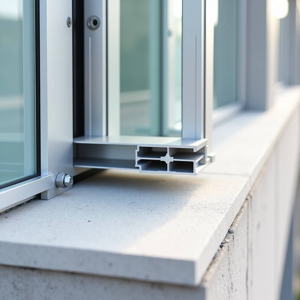
When a curtain wall contractor calls with a problem on site, the issue rarely starts with the panel. It starts with the bracket. The Aluminum Facade Bracket is the component that bridges the building structure and the cladding system, carrying dead loads, wind loads, and thermal movement across decades of service. A bracket that is underspecified, poorly extruded, or installed without accounting for differential movement will telegraph its failures through the entire facade, cracking panels, leaking air barriers, and triggering costly remedial work. This article examines the engineering logic behind aluminum facade brackets, the material grades that actually perform in the field, the load-path calculations that separate reliable systems from guesswork, and the procurement decisions that determine whether a project stays on schedule or stalls waiting for replacement parts.
What an Aluminum Facade Bracket Actually Does
At its simplest, an aluminum facade bracket transfers loads from the outer cladding layer into the primary structural frame. But that description undersells the complexity. A single bracket in a ventilated facade system must handle three distinct load types simultaneously. Vertical dead loads come from the self-weight of the panels, carrier rails, insulation, and the bracket itself. Horizontal wind loads push and pull the facade, creating both pressure and suction forces that the bracket must resist without excessive deflection. Thermal loads arise from daily and seasonal temperature swings, which can move aluminum components by several millimeters over a typical floor-to-floor span.
The bracket is also the point where thermal bridging gets either solved or ignored. A bracket that connects the cold outer cladding directly to the warm interior structure without a thermal break creates a linear thermal bridge. Over thousands of brackets across a building envelope, this adds up to significant energy loss. Modern Aluminum Facade Bracket designs incorporate polyamide or polyurethane thermal isolators that cut heat transfer while maintaining structural continuity. The engineering challenge is that adding a thermal break introduces a flexible element into a load path that needs stiffness. Getting this right requires precise extrusion design and material selection.
Material Grades That Matter in the Field
Not all aluminum is interchangeable. The alloy and temper designation stamped on the mill certificate determines how the bracket behaves under load, how it responds to drilling and cutting on site, and whether it will develop stress corrosion cracking in coastal environments. Three grades dominate the facade bracket market, each with distinct properties.
6061-T6 aluminum offers high tensile strength, typically around 310 MPa, and responds well to welding and machining. This grade appears frequently in North American projects and is specified by manufacturers who prioritize structural capacity. It performs well in most environments but requires protective anodizing or coating in marine exposures. 6063-T6 provides slightly lower strength, around 240 MPa, but extrudes more easily into complex profiles. This makes it the preferred choice for brackets with intricate cross-sections that combine multiple functions such as vertical adjustment, thermal break grooves, and rail attachment channels into a single extrusion. EN AW-5052, an Al-Mg alloy, offers superior corrosion resistance and moderate strength. It is commonly specified in European rainscreen systems, particularly for coastal installations where salt spray would attack heat-treated alloys.
The temper designation matters as much as the alloy. T6 indicates solution heat-treated and artificially aged, producing maximum strength but reduced ductility. T5, which is cooled from the extrusion temperature and artificially aged, offers a balance of strength and formability. Specifying the wrong temper can mean the difference between a bracket that holds its shape under load and one that fractures at the bolt hole.
| Alloy Grade | Tensile Strength (MPa) | Corrosion Resistance | Typical Application | Extrudability |
|---|---|---|---|---|
| 6061-T6 | 310 | Moderate | Heavy curtain wall, high-wind zones | Good |
| 6063-T6 | 240 | Moderate | Complex profiles, rainscreen brackets | Excellent |
| EN AW-5052 | 210-260 | High | Coastal facades, marine environments | Moderate |
| 6082-T6 | 310 | Moderate | European structural applications | Good |
Load Path Engineering: From Panel to Structure
A properly designed bracket system creates a clear, calculable load path. The sequence starts with wind pressure on the cladding panel, which transfers to the carrier rails through rivets or screws. The rails deliver the load to the bracket through a mechanical connection, typically a bolt or a dovetail interlock. The bracket then carries the combined dead and wind loads into the building substrate, whether that is concrete, steel stud, or masonry.
Each connection point in this chain introduces a potential failure mode. The bracket-to-rail connection must resist pull-out and shear. The bracket-to-structure connection, usually an anchor bolt, must be sized for the substrate material. Concrete anchors in cracked concrete behave differently from those in uncracked concrete, and the European Technical Assessment (ETA) for the anchor will specify the design resistance for both conditions. Steel stud connections require the bracket to span across the stud flange and engage the web, not just the thin edge of the flange.
Adjustability is a practical requirement that complicates the engineering. Brackets need vertical slots to accommodate slab level tolerances, horizontal slots for lateral adjustment, and sometimes shimming capability for out-of-plane corrections. Every slot reduces the effective cross-section of the bracket and introduces a stress concentration at the slot ends. The slot geometry, length, width, and end radius, must be engineered to ensure the bracket retains adequate capacity at maximum adjustment. A bracket that meets its design load at mid-slot position might fail at the extreme end of the slot where the bolt bearing area is reduced.
Thermal Performance and the Bracketry Problem
Building codes increasingly demand that thermal bridges be accounted for in energy calculations. The ASHRAE 90.1 standard and the International Energy Conservation Code require continuous insulation in many climate zones, and a metal bracket penetrating that insulation layer creates a point thermal bridge. The heat flow through a single bracket is small, but the cumulative effect across a building can reduce the effective R-value of the wall assembly by 20-40% depending on bracket density and design.
The solution is a thermally broken bracket. These brackets separate the outer load-bearing component from the inner anchor component with a polyamide or polyurethane isolator. The isolator material has thermal conductivity roughly 1/200th that of aluminum. The structural connection between the two halves is typically achieved through a mechanical interlock or a stainless steel pin that passes through the isolator. The pin itself is a thermal bridge, but its cross-sectional area is small enough that the overall heat transfer remains low.
The trade-off is cost and complexity. Thermally broken brackets cost two to three times more than solid brackets. They also require more careful handling on site, as the isolator can be damaged by impact or excessive torque during installation. For projects where thermal performance is a priority, the investment pays back through reduced heating and cooling loads. For unconditioned buildings or industrial applications, solid brackets may be the pragmatic choice. Suppliers like Futeng® offer both configurations, allowing project teams to match the bracket type to the performance specification without switching vendors mid-project.
Corrosion Protection Beyond the Alloy
Even corrosion-resistant alloys benefit from surface treatment. Anodizing creates a controlled aluminum oxide layer that is harder than the base metal and provides excellent atmospheric corrosion resistance. The standard for architectural anodizing is AA-M12C22A31 (Class I, 0.7 mil minimum thickness), referenced in AAMA 611. For coastal or industrial environments, Class I anodizing with a minimum 0.7 mil coating is the baseline specification.
Powder coating offers an alternative with a wider color range. Qualicoat and AAMA 2605 govern the powder coating standards for architectural aluminum. The coating thickness, typically 60-80 microns for standard applications, provides a durable barrier against moisture and pollutants. The challenge with powder coating on brackets is that the coating can chip at bolt holes and contact points during installation, creating initiation sites for corrosion. Some manufacturers address this by masking threaded holes before coating, or by specifying stainless steel washers that distribute the bolt load and protect the coating.
For projects in the Middle East, Southeast Asia, or other high-humidity coastal regions, the combination of alloy selection and surface treatment becomes critical. A 6061-T6 bracket with Class I anodizing will perform well in Dubai or Singapore. A 5052 bracket with the same treatment adds an extra margin of safety. The cost difference is modest compared to the cost of replacing corroded brackets on a 40-story tower.
Installation Realities That Affect Bracket Performance
The best-engineered bracket fails if it is installed incorrectly. The most common site errors include over-torquing anchor bolts, which can strip threads in aluminum or crack the bracket at the slot; using the wrong anchor type for the substrate, such as a wedge anchor in hollow brick; and failing to verify that the bracket is bearing flat against the substrate, which introduces bending moments that the bracket was not designed to carry.
Slotted holes require particular attention. The bolt should be positioned near the center of the slot at the time of installation, leaving adjustment range in both directions. If the bolt is tightened at the extreme end of the slot, the bracket has no room to accommodate thermal expansion of the rail, and the resulting stress can shear the bolt or deform the bracket. A simple site rule is that the bolt should never be closer than 5 mm from the end of any slot after final tightening.
The substrate itself must be evaluated. Concrete that is spalled, cracked, or poorly consolidated will not hold an anchor at its rated capacity. Steel studs that are not properly braced can twist under load, rotating the bracket and the attached cladding. Masonry walls require careful anchor selection, as the holding capacity varies dramatically between solid brick, hollow block, and the mortar joints between them. A AAMA publication on anchor testing provides guidance on pull-out testing procedures that should be part of every project's quality assurance plan.
Sourcing Decisions: Standard vs. Custom Brackets
Standard brackets from established manufacturers cover a wide range of applications. They are available in multiple depths, typically 80 mm to 300 mm, to accommodate different insulation thicknesses and cavity widths. They come with pre-engineered load tables that the design team can use without commissioning additional calculations. Lead times are short, often two to four weeks, and pricing is competitive.
Custom brackets become necessary when the project geometry or loading exceeds the range of standard products. A curved facade may require brackets with variable projection. A high-wind location may demand thicker sections or additional stiffening ribs. A project with an unusual substrate, such as cross-laminated timber, may need a bracket with a specialized anchor pattern. Custom extrusions require a die to be manufactured, which adds four to six weeks to the lead time and a one-time tooling cost.
The decision between standard and custom should be made early in the design phase. Waiting until the submittal stage to discover that standard brackets do not fit the as-built conditions is a schedule disaster. The procurement team should review the bracket specification at the same time as the panel specification, not as an afterthought. A single Aluminum Facade Bracket type that works across the entire project simplifies installation, reduces the risk of mix-ups on site, and allows the contractor to develop a rhythm during installation.
Quality Verification and Mill Certification
When a container of brackets arrives on site, the paperwork matters as much as the product. The mill certificate should confirm the alloy grade, temper, and mechanical properties of the extrusion. Third-party inspection reports should verify the coating thickness and adhesion. Dimensional checks should confirm that the bracket matches the approved shop drawings within the specified tolerances, typically ±1 mm for critical dimensions.
A simple field test is to weigh a sample of brackets and compare the weight to the theoretical weight calculated from the cross-sectional area. Underweight brackets indicate a thinner section than specified, which reduces load capacity. This test takes minutes and can prevent a systemic problem from being installed across the building.
For projects requiring seismic performance, the bracket system may need to be tested as part of a full-scale mockup. The ASTM E330 test for uniform static air pressure difference and the AAMA 501.1 dynamic water penetration test are standard references. Seismic testing follows AAMA 501.4 or the project-specific protocol developed by the structural engineer. The bracket is not tested in isolation but as part of the complete cladding assembly, and failures at the bracket connection are among the most common findings in these tests.
Cost Drivers in Bracket Specification
The cost of aluminum facade brackets is driven by alloy grade, extrusion complexity, surface treatment, thermal break inclusion, and order volume. A simple 6063-T6 L-bracket without thermal break might cost a few dollars per unit. A thermally broken 6061-T6 bracket with a complex profile, Class I anodizing, and stainless steel hardware could cost ten times that amount. Across a large facade with brackets at 600 mm centers horizontally and 1200 mm vertically, the bracket cost can range from $15 to $60 per square meter of facade area.
What is often overlooked is the cost of the bracket relative to the total facade system cost. The bracket typically represents 3-8% of the total facade cost. Saving 20% on brackets by specifying a lower grade might reduce the total project cost by less than 1%. If that saving results in a single corrosion failure or structural issue, the remediation cost will exceed the saving by orders of magnitude. The smarter procurement strategy is to specify the bracket that meets the performance requirements with an appropriate safety margin, not the cheapest bracket that barely passes the load calculation.
The ISO 9001 quality management certification of the bracket manufacturer provides some assurance of consistent production quality. For projects where the brackets are sourced internationally, the certification should be verified, and the specifier should confirm that the testing standards referenced in the mill certificates are equivalent to the project requirements. A certificate that references a standard unfamiliar to the project engineer is of limited value.
Integrating Brackets with the Broader Facade System
The bracket does not exist in isolation. It must be compatible with the carrier rail system, the cladding panel attachment method, the insulation type and thickness, the air and water barrier, and the substrate. A bracket that works perfectly with one rail system may be incompatible with another due to differences in the connection geometry. The bracket projection must account for the insulation thickness plus the ventilated cavity depth, typically 20-50 mm, plus the rail depth, plus any shimming or adjustment allowance.
When the cladding panels are solid aluminum sheets, the bracket system must accommodate the panel attachment method. Panels are typically attached to the rails using concealed clips, exposed fasteners, or cassette systems. The bracket spacing must align with the panel joint layout, and the bracket capacity must account for the load concentration at the panel corners where wind suction is highest. A NFPA 285-compliant facade assembly requires that the bracket and rail system maintain their structural integrity during a fire exposure, which may necessitate stainless steel brackets in certain fire-rated assemblies, though aluminum brackets with appropriate design can meet the requirements for many applications.
The bracket system is also the interface where the facade contractor's work meets the general contractor's work. The anchors are typically installed by the GC or a specialist anchor contractor, while the brackets and rails are installed by the facade contractor. This division of responsibility creates a coordination risk. The anchor positions must match the bracket layout, and the anchor capacity must be verified for the as-built substrate conditions. A pre-installation conference that brings together the anchor installer, the facade contractor, and the bracket supplier can resolve these coordination issues before they become field problems.
For project teams evaluating solid aluminum cladding systems, the bracket selection should proceed in parallel with panel selection. A technically sound panel mounted on an underspecified bracket is a system waiting to fail. The reverse is also true: an over-engineered bracket adds unnecessary cost without improving performance. The right approach is to treat the bracket as an engineered component, not a commodity, and to select it based on calculated loads, verified material properties, and proven compatibility with the complete facade assembly.