Aluminum Facade Prototype Assembly What a Full Scale Mock Up Actually Reveals
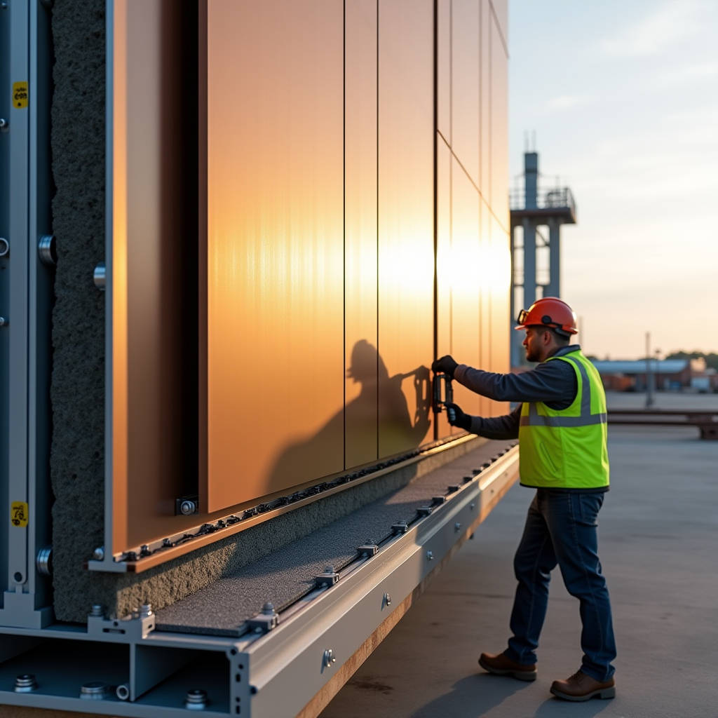
When a project team commits to solid aluminum cladding, the gap between a pristine 3D render and a weathertight installed facade narrows at exactly one point: the prototype assembly phase. An Aluminum Facade Prototype Assembly is not a sample board glued together for a boardroom presentation. It is a full-scale, fully engineered mock-up that replicates the actual substructure, panel joints, gaskets, fasteners, and perimeter flashings exactly as they will appear on the building. This assembly answers questions that shop drawings cannot. Will the 3.0mm PVDF-coated panel oil-can under direct afternoon sun? Does the rainscreen cavity drain correctly when wind-driven rain hits the joint at 30 degrees? Can the installer actually reach the rear fixing with a torque wrench when the cavity is only 80mm deep?
For general contractors and facade engineers, the prototype is the last line of defense before hundreds of panels arrive on site. A single overlooked detail—a gasket that kinks at a corner, a bracket that interferes with insulation, a panel edge that chips because the fold radius was too tight—can cascade into six-figure remedial costs. The Aluminum Facade Prototype Assembly process, when executed rigorously, exposes these gremlins while there is still time to adjust CNC programs, modify extrusion dies, or retrain installation crews. This article walks through what a proper prototype assembly entails, from material selection and structural testing to the specific failure modes that only reveal themselves at full scale.
What Separates a Prototype Assembly from a Sample Panel
Confusion between a sample panel and a prototype assembly persists across the industry, and it costs money. A sample is typically a single panel—often 600mm by 600mm—mounted to a piece of plywood with no insulation, no air cavity, and no adjacent panels. It shows color and finish. It does not show how the system behaves.
A true Aluminum Facade Prototype Assembly replicates a complete section of the facade, usually spanning at least two structural bays and one full floor-to-floor height. It includes the primary steel or aluminum substructure, thermal isolation pads, the rainscreen cavity, continuous insulation, air and water barriers, all panel-to-panel joints, and the interfaces with windows, louvers, or parapets. The assembly must be oriented vertically, exactly as it will hang on the building, because gravity affects drainage paths and panel deflection.
Gebrüder Schneider, a German facade specialist, builds prototypes on dedicated sample towers at their facility, using original materials and identical fixing methods. They test appearance, functionality, and safety before any production panel is cut. This approach reflects a hard-won understanding: the prototype is not a cosmetic exercise. It is a structural and weatherproofing validation tool.
Material Selection and the Solid Aluminum Distinction
Every prototype begins with the base metal. Solid aluminum cladding panels—as distinct from aluminum composite material (ACM)—are manufactured from monolithic sheets of alloy, typically 5052, 5754, or 6061, depending on the required balance of formability, corrosion resistance, and strength. Thicknesses range from 2.0mm to 3.0mm for most architectural applications, though 4.0mm and 5.0mm are specified for high-wind zones or large-format panels exceeding 1500mm in any dimension.
The alloy choice matters at the prototype stage because it dictates the minimum bend radius achievable without cracking. A 5052-H32 sheet at 2.5mm thickness can typically be bent to an inside radius of 1.5 times the material thickness. Attempting a tighter radius risks micro-cracking along the fold line—a defect that may not be visible immediately after fabrication but can propagate under thermal cycling and wind loading. The prototype assembly exposes these cracks because panels are subjected to repeated handling, mounting, and demounting during the testing sequence.
For projects requiring complex geometries—folded cassettes with returns on all four sides, perforated screens, or curved panels—the prototype should include at least one of each geometry type. Suppliers like Futeng® who operate their own CNC punching and folding centers can adjust tooling parameters based on prototype feedback, reducing lead time on production panels.
Structural Testing and Deflection Under Wind Load
Wind load performance is the most quantifiable aspect of any Aluminum Facade Prototype Assembly. The governing standard in most markets is ASTM E330, which specifies a uniform static air pressure difference applied to the test specimen. For a typical mid-rise commercial building in a 150 mph wind zone, the design pressure might be 2.4 kPa (50 psf), with a safety factor of 1.5 bringing the test pressure to 3.6 kPa (75 psf).
The prototype must be instrumented with dial gauges or LVDTs (linear variable differential transformers) at the panel center and at mid-span of each supporting rail. The allowable deflection under design load is typically L/175 for aluminum panels, where L is the span between supports. For a panel spanning 1200mm between horizontal rails, the maximum allowable deflection is 6.9mm. If the prototype measures 9.0mm, the engineering team has three options: increase panel thickness from 2.5mm to 3.0mm, reduce the support spacing, or add stiffeners bonded to the rear face.
Stiffener design is a frequent source of prototype failure. Extruded aluminum stiffeners are typically bonded to the panel rear with structural adhesive tape or two-part epoxy. The prototype assembly tests whether the adhesive creeps under sustained load at elevated temperatures. A common test protocol exposes the assembly to 80°C for four hours while maintaining the design load, then checks for any permanent deformation after cooling. Panels that pass this test have a stiffener bond that will survive a dark-colored facade in a Phoenix or Dubai summer.
Water Penetration and Drainage Verification
A rainscreen facade is not a sealed barrier. It is designed to manage water that penetrates the outer cladding layer, channeling it down the rear face of the panel and out through weep holes at the base. The Aluminum Facade Prototype Assembly verifies that this drainage path actually works.
Testing follows ASTM E1105 or AAMA 501.1, which apply a water spray at a rate of 3.4 L/min per square meter while maintaining a static pressure differential across the assembly. The spray runs for 15 minutes. At the end of the test, the cavity behind the panels should be inspected for standing water, damp insulation, or water that has reached the structural backup wall. Any moisture on the air barrier is a failure.
The most common failure point is the horizontal joint between panels. Even with a 10mm open joint, wind-driven rain can bridge the gap if the joint profile does not incorporate a pressure-equalization chamber. The prototype reveals whether the joint geometry—specifically the depth of the rear baffle and the placement of the gasket relative to the drainage plane—performs under real conditions. Adjustments made at this stage cost a few hours of engineering time. The same adjustment made after 2,000 panels are installed costs a project's reputation.
Thermal Movement and Joint Design
Aluminum expands at approximately 0.024mm per meter per degree Celsius. For a 4-meter-long panel subjected to a 60°C temperature swing between winter night and summer afternoon, the total movement is 5.76mm. If the panel is fixed rigidly at both ends, this movement translates into buckling stress that can permanently deform the panel face.
The prototype assembly must demonstrate that the fixing system accommodates thermal movement. Typically, each panel is fixed at one point (the "dead" fixing) and allowed to slide at all other points via slotted holes in the support brackets. The prototype should be cycled through a temperature range—or at minimum, the fixings should be checked for binding when panels are installed and removed. A panel that is difficult to remove because the fixings are jammed is a panel that will buckle in service.
Joint width is the other thermal variable. A 10mm joint at 20°C installation temperature will close to approximately 7.6mm at 60°C and open to 12.4mm at -20°C. The prototype should include joints at the minimum and maximum expected widths to verify that gaskets remain engaged and that the visual appearance is acceptable across the full range.
Coating Performance and Color Consistency
PVDF (polyvinylidene fluoride) coatings dominate the architectural aluminum market because they resist chalking, fading, and chemical attack for decades. The industry benchmark is AAMA 2605, which requires a minimum 70% PVDF resin content by weight in the color coat and a total dry film thickness of at least 30 microns for a two-coat system or 40 microns for a three-coat system.
The prototype assembly serves as the color reference standard for the entire project. Under AAMA 2605, color consistency is measured using a spectrophotometer and must fall within a Delta E of 2.0 (CIELAB) compared to the approved standard. The prototype should be measured at multiple points—panel center, edges, and any folded returns—because the coating thickness can vary on complex geometries.
One test that only a full-scale prototype can provide is the visual assessment of color under different lighting conditions. A panel that matches perfectly under the factory's 5000K fluorescent lights may look noticeably different under the 6500K northern sky. Architects should review the prototype outdoors at multiple times of day before signing off on production.
| Coating Standard | PVDF Resin Content | Min. Dry Film Thickness | Typical Warranty | Best Application |
|---|---|---|---|---|
| AAMA 2604 | 50% minimum | 25 microns (2-coat) | 10-15 years | Low-rise, sheltered facades |
| AAMA 2605 | 70% minimum | 30 microns (2-coat) | 20-30 years | High-rise, exposed locations |
| FEVE (Lumiflon) | N/A (fluoropolymer) | 30 microns | 20-30 years | Coastal, high-UV environments |
| Powder (Qualicoat Class 2) | N/A (polyester/TGIC) | 60 microns | 15-20 years | Interior, moderate exterior |
Acoustic Performance and Rain Noise
An often-overlooked function of the Aluminum Facade Prototype Assembly is acoustic testing. Solid aluminum panels, particularly large-format ones, can act as diaphragms that transmit rain impact noise into the building interior. This is especially problematic for hotels, residential towers, and hospitals where nighttime noise levels are tightly regulated.
The prototype can be tested using a rain simulator—essentially a calibrated water droplet generator—while sound level meters measure the transmitted noise in a receiving room behind the assembly. The results are compared against project specifications, which might require a weighted sound reduction index (Rw) of 45 dB or higher for the complete facade build-up.
If the prototype exceeds the noise limit, mitigation options include adding a layer of mass-loaded vinyl to the panel rear, increasing the insulation density in the cavity, or specifying a perforated panel with an acoustic fleece backing. These are inexpensive modifications at the prototype stage but would be ruinously expensive to retrofit.
Installation Sequence and Access Constraints
The prototype assembly is as much about the installer as it is about the panel. A well-designed panel that cannot be installed because the fixing is inaccessible behind a 60mm cavity is a design failure. The prototype must be assembled by the actual installation crew—not the factory technicians—using the tools and access equipment that will be available on site.
Key questions the prototype answers: Can the installer reach the top fixing of a 3.5-meter panel from a standard mast climber? Does the panel need a temporary lifting lug, and if so, does the lug leave a mark that requires touch-up? How many crew members are needed to safely position a panel that weighs 35 kg? The answers feed directly into the installation rate estimate, which drives the project schedule and cost.
For unitized systems where panels are pre-assembled into larger modules off-site, the prototype should include a full unit—typically one floor height by one structural bay—to verify that the module can be lifted, positioned, and fixed without damage. The connection between units is the critical interface; a 2mm misalignment at the prototype stage translates to a 20mm cumulative error across a 10-unit elevation.
Fire Performance and Compliance Documentation
Solid aluminum panels are non-combustible, classified as A1 under EN 13501-1 when tested as a standalone material. However, the complete facade assembly—including insulation, vapor barriers, gaskets, and sealants—must be tested as a system. The relevant large-scale test is NFPA 285 (in North America) or BS 8414 (in the UK and Middle East), which evaluates vertical flame propagation across a multi-story facade mock-up.
The Aluminum Facade Prototype Assembly, if built to the full scale required by these standards, can serve as the test specimen. This is a significant investment—a full NFPA 285 test costs upwards of $30,000—but it is mandatory for buildings over 40 feet in many jurisdictions. The prototype should include all combustible components in their worst-case configuration: the thickest insulation, the largest gasket cross-section, the most flammable vapor barrier.
Documentation from the prototype assembly feeds into the project's compliance package. Photographs of each assembly step, torque values for every fastener, batch numbers for sealants and adhesives—all of this becomes part of the quality assurance record that the facade consultant reviews before signing off on production.
Digital Integration: BIM and the Prototype Feedback Loop
The prototype assembly closes the loop between the digital model and the physical panel. Most projects today are designed in BIM (Building Information Modeling) software, with each panel modeled as an individual element containing its dimensions, material grade, coating specification, and fixing coordinates. The prototype validates whether the BIM model accurately represents the as-built condition.
Any discrepancy found during the prototype assembly—a bracket that clashes with a window frame, a panel that is 3mm longer than the model predicted—must be fed back into the BIM model before production drawings are finalized. This requires a disciplined change management process. Some fabricators, including Futeng®, use cloud-based project management platforms where prototype findings are logged, photographed, and linked to the affected BIM elements, ensuring that every stakeholder sees the updated information in real time.
Laser scanning the completed prototype and overlaying the point cloud on the BIM model provides a quantitative check of dimensional accuracy. A tolerance of ±2mm is generally achievable and should be specified in the project's facade tolerances schedule.
Cost and Schedule Implications of a Proper Prototype
A full-scale Aluminum Facade Prototype Assembly typically costs between $8,000 and $25,000, depending on size, complexity, and the number of interfaces. This is not a line item to be value-engineered out. The cost of discovering a systemic defect after production panels are fabricated is an order of magnitude higher. A single container of rejected panels shipped back from a project site in North America to a factory in Asia can cost $15,000 in freight alone, plus the schedule delay, plus the cost of remanufacturing.
The prototype should be scheduled at least 8 to 12 weeks before the first production panels are required on site. This allows time for fabrication of the prototype (2-3 weeks), assembly and testing (2-3 weeks), design revisions based on findings (1-2 weeks), and re-testing of any modified details (2-3 weeks). Projects that compress this timeline almost always pay for it later.
For procurement managers, the prototype is also a valuable tool for evaluating potential suppliers. A fabricator who delivers a complete, well-documented prototype assembly on schedule demonstrates the organizational capability to handle the full production run. One who struggles with the prototype will struggle with the project.
Common Failure Modes Uncovered Only at Full Scale
After years of reviewing prototype assemblies, certain failure modes recur with predictable regularity. The most common are: oil-canning (visible waviness on flat panel surfaces caused by residual stress from the rolling process, exacerbated by dark colors and direct sun); gasket pull-out at corners (where the gasket is stretched around a tight radius and pops out of the extrusion groove); fastener corrosion (where stainless steel fasteners specified for the prototype are substituted with zinc-plated steel by a well-meaning but uninformed installer); and drainage blockage (where insulation fluff, drilling swarf, or sealant squeeze-out blocks the weep holes at the base of the cavity).
Each of these failures is trivial to fix at the prototype stage. Oil-canning is addressed by specifying a higher-grade alloy or adding stiffeners. Gasket pull-out is solved by adjusting the corner radius or using a molded corner piece. Fastener corrosion is a procurement discipline issue. Drainage blockage is a workmanship issue that the prototype highlights and the site supervisor can then police during production installation.
The Aluminum Facade Prototype Assembly exists precisely to catch these problems. It is a controlled failure exercise—a deliberate search for everything that can go wrong, conducted in a factory yard or test laboratory rather than 30 stories up on a swing stage. Projects that invest in this process, and that work with fabricators who understand its value, consistently deliver facades that look right, drain right, and stay right for decades. The alternative is a gamble that no competent project team should take.