Aluminum Panel Weld Quality Test Methods and Acceptance Criteria for Solid Cladding Fabrication
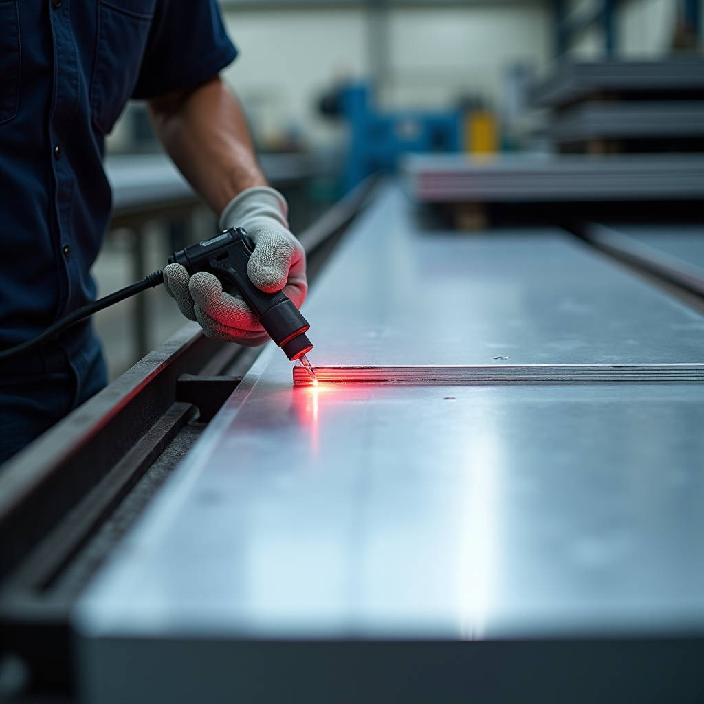
When a 3mm solid aluminum panel comes off the fabrication line with welded stiffener ribs, the difference between a 20-year facade and a premature failure lives in the weld zone. An Aluminum Panel Weld Quality Test is not a box-ticking exercise at the end of production. It is the only verifiable method to confirm that the heat-affected zone around each stud and stiffener attachment has not compromised the panel's structural integrity or introduced micro-cracking that will propagate under thermal cycling. For architects specifying large-format cladding and contractors responsible for installation on high-rise envelopes, understanding what passes and what fails in these tests directly determines whether a rainscreen performs as designed or becomes a liability. This article examines the specific test protocols that matter for solid aluminum panels, the acceptance criteria that separate cosmetic issues from structural defects, and how to interpret test reports from fabricators.
Why Solid Aluminum Panel Welds Demand Different Testing Logic
Welding on solid aluminum panels—typically 2.0mm, 2.5mm, or 3.0mm thick 1xxx, 3xxx, or 5xxx series alloys—presents challenges that steel testing protocols never anticipated. The fundamental issue is thermal conductivity. Aluminum dissipates heat roughly five times faster than steel. This means the weld pool solidifies rapidly, and the heat-affected zone (HAZ) extends further laterally than a welder might expect. For a 3mm panel with MIG-welded aluminum stiffener ribs, the HAZ can reduce the tensile strength of the parent material by 30-50% in non-heat-treatable alloys, and even more in heat-treatable grades like 6061 if post-weld heat treatment is not performed.
The second issue is porosity. Aluminum's high affinity for hydrogen means that moisture in the air, hydrocarbon contaminants on the panel surface, or even humidity absorbed by the filler wire can generate gas porosity during solidification. A weld that looks acceptable on visual inspection can contain subsurface porosity that reduces effective throat thickness by 20% or more. This is why an Aluminum Panel Weld Quality Test must go beyond what a fillet gauge can measure.
The third challenge is solidification cracking, also called hot cracking. Aluminum alloys with high silicon or copper content are particularly susceptible. When a stiffener is welded to the back of a panel and the weld bead contracts during cooling, the semi-solid metal can tear if it cannot accommodate the shrinkage strain. This is not a theoretical concern—panels have arrived on site with partial stiffener detachment that originated from hot cracks invisible beneath the weld surface.
The Test Hierarchy: What Actually Matters for Cladding Panels
Not every test in the welding inspector's handbook applies to aluminum cladding panels. A pressure vessel weld and a stiffener-to-panel fillet weld serve different functions and fail in different ways. The following hierarchy reflects what experienced facade engineers and quality managers prioritize when auditing a fabricator's weld quality program.
1. Visual Inspection (VT) — The First Gate
Visual testing per ISO 17637 remains the most immediate and cost-effective screening method. For aluminum panel welds, the inspector should examine:
- Weld surface condition: No open cracks, no crater cracks at the end of intermittent stiffener welds, no exposed undercut deeper than 0.5mm on a 2.5mm panel.
- Fillet weld profile: Using a fillet weld gauge, the inspector checks leg length, throat thickness, convexity, and concavity. For a 3mm stiffener-to-panel weld, a typical specification calls for a 3mm leg length with a throat thickness of at least 2.1mm (0.7 × leg length for a convex fillet).
- Color and oxidation: Excessive black soot or a dull gray, heavily oxidized surface indicates inadequate shielding gas coverage. This is not merely cosmetic—it signals potential subsurface porosity.
- Arc strikes outside the weld zone: Stray arc strikes on the visible face of the panel are unacceptable and usually result in panel rejection.
Visual inspection catches roughly 70-80% of weld defects that matter for cladding applications. But it cannot detect subsurface porosity, lack of fusion, or root defects. That is where NDT methods enter the picture.
2. Dye Penetrant Testing (PT) — Surface Crack Detection
For aluminum, PT is the go-to method for detecting surface-breaking discontinuities. Unlike magnetic particle testing, which is useless on non-magnetic aluminum, dye penetrant works reliably. The process involves cleaning the weld area, applying a visible or fluorescent penetrant, allowing dwell time (typically 10-30 minutes depending on temperature), removing excess penetrant, and applying developer.
For aluminum panel welds, PT is particularly valuable for identifying:
- Crater cracks at weld terminations
- Transverse cracks across the weld bead
- Toe cracks along the weld-to-panel interface
- Micro-cracks in the HAZ that may have formed during rapid cooling
A common specification for aluminum cladding weld acceptance is that no linear indications exceeding 2mm in length are permitted, and no rounded indications exceeding 3mm in diameter are acceptable. These thresholds align with EN ISO 10042 quality level B (stringent) or C (intermediate) depending on the project specification.
3. Radiographic Testing (RT) — Seeing Inside the Weld
When a project specification demands documented evidence of internal weld soundness—common for landmark buildings, blast-resistant facades, or panels subjected to high wind loads—radiographic testing becomes necessary. RT uses X-rays or gamma rays to produce an image showing density variations within the weld.
On aluminum panels, RT reveals:
- Subsurface porosity: Individual pores or clusters appear as dark spots on the film. Codes such as AWS D1.2 (Structural Welding Code — Aluminum) specify maximum permissible porosity sizes based on weld thickness.
- Lack of fusion: Appears as dark linear indications along the weld interface, indicating that the filler metal did not bond properly with the parent material.
- Tungsten inclusions: Small, high-density particles from the TIG electrode that appear as bright spots.
- Incomplete penetration: In butt welds (less common in panel fabrication but used in some architectural applications), RT shows whether the weld penetrated to the root.
RT is expensive and slow. It requires radiation safety protocols and skilled interpretation. For most standard cladding projects, RT is reserved for a sampling plan—perhaps 5-10% of welds on critical panels, or 100% of welds on the first article inspection. The cost-benefit calculation shifts when the consequence of failure is high.
4. Phased Array Ultrasonic Testing (PAUT) — The Modern Standard
PAUT has rapidly become the preferred NDT method for aluminum welds in advanced fabrication facilities. Unlike conventional UT, which uses a single-element probe, PAUT employs multiple elements that can be electronically steered and focused. This produces a cross-sectional image of the weld in real time.
For aluminum panel welds, PAUT offers several advantages:
- Speed: A PAUT scan can cover a meter of weld in minutes, with immediate on-screen visualization.
- No radiation: Unlike RT, PAUT requires no exclusion zones or safety cordons.
- Depth sizing: PAUT can accurately measure the depth and height of discontinuities, not just their length. This is critical for determining whether a flaw exceeds acceptance criteria.
- Data recording: Full scan data can be stored and reviewed later, providing an audit trail that RT film also offers but with easier digital archiving.
The limitation of PAUT on thin aluminum panels (2.0-3.0mm) is the near-surface dead zone. Discontinuities within approximately 1-2mm of the scanning surface can be difficult to resolve. This is why PAUT is often combined with PT for a complete inspection.
EN ISO 10042: The Acceptance Criteria That Governs Aluminum Welds
For fabricators supplying the European, Middle Eastern, and Asian markets, EN ISO 10042 is the defining standard. It specifies three quality levels for aluminum arc-welded joints:
| Quality Level | Typical Application | Porosity Limit (Single Pore) | Undercut Limit | Incomplete Penetration |
|---|---|---|---|---|
| B (Stringent) | High-stress architectural, blast-resistant, seismic | d ≤ 0.2 × s, max 3mm | Not permitted for full penetration | Not permitted |
| C (Intermediate) | Standard architectural cladding, rainscreens | d ≤ 0.3 × s, max 4mm | h ≤ 0.5mm, intermittent acceptable | Short intermittent permitted |
| D (Moderate) | Non-structural, decorative, internal linings | d ≤ 0.4 × s, max 5mm | h ≤ 1.0mm | Permitted within limits |
Note: s = nominal butt weld thickness. For fillet welds, throat thickness is the reference dimension.
For most aluminum cladding panel applications, quality level C is specified. This provides a practical balance between manufacturing cost and structural reliability. Level B is reserved for panels that carry significant structural load or are installed in extreme environments—coastal high-rises with typhoon wind loads, for example. Level D is generally insufficient for external cladding because it permits undercut depths that can initiate corrosion in the weld zone.
The standard also addresses specific imperfections: lack of fusion, oxide inclusions, excess weld metal, and misalignment. Each has quantitative limits at each quality level. A fabricator's test report should reference the specific quality level and list each imperfection type with measured values against the acceptance threshold.
Destructive Testing: When You Cut Panels to Prove the Process
Destructive testing is performed on sample panels or test coupons, not on production panels. Its purpose is to qualify the welding procedure specification (WPS) and the welder's skill before production begins.
Bend Testing
Bend testing is the most revealing destructive test for aluminum panel welds. A 1.5-inch-wide (38mm) specimen is cut so the weld runs across the width. The specimen is then bent around a mandrel—typically to 180 degrees—with the weld face in tension (face bend) or the weld root in tension (root bend).
Aluminum behaves differently from steel in bend testing. The lower ductility of some aluminum alloys, combined with the reduced strength in the HAZ, means that bend specimens often fail in the HAZ rather than in the weld metal itself. This is not necessarily a rejection criterion—it depends on the code and the extent of the discontinuities revealed by the bend.
Per AWS D1.2, a bend test is acceptable if no single discontinuity exceeds 3mm in any direction, and the sum of all discontinuities exceeding 1mm does not exceed 10mm. Cracks initiating at the specimen edges are disregarded unless they propagate into the weld zone.
Macro-Etch Testing
A cross-section of the weld is cut, polished, and etched with an acid solution (typically Keller's reagent for aluminum) to reveal the weld profile, penetration depth, fusion line, and HAZ. Under magnification, the macro-etch shows:
- Whether the weld penetrated to the root
- The extent of the HAZ (visible as a color change in the etched surface)
- Any internal porosity or oxide inclusions
- The grain structure transition from parent metal to weld metal
For a 3mm panel with a fillet-welded stiffener, the macro-etch should show complete fusion at the weld toes, no crack-like discontinuities, and a HAZ that does not extend through more than 50% of the panel thickness. This is a one-time test during procedure qualification, but it provides the most complete picture of weld quality available.
Common Failure Modes and What They Mean for the Project
Understanding what a failed test looks like helps procurement managers and site engineers make informed decisions about accepting or rejecting panels. The following failure modes are encountered regularly in aluminum panel fabrication:
Crater cracking: The most common defect in intermittent stiffener welds. When the welding arc is extinguished, the molten pool solidifies rapidly and shrinks. Without proper crater filling technique, a star-shaped crack forms. These cracks can propagate under thermal cycling. A panel with crater cracks exceeding 2mm should be rejected or repaired per an approved procedure.
Porosity clusters: On an RT film, these appear as a line of dark spots along the weld centerline. They often indicate contaminated filler wire or inadequate shielding gas coverage. Isolated pores below the acceptance threshold are generally acceptable, but clusters that reduce the effective weld cross-section by more than 5% are cause for rejection.
Lack of fusion at the weld toe: This is particularly dangerous because it creates a stress concentration exactly where bending stresses are highest. On a panel subjected to wind suction, the stiffener-to-panel weld experiences tensile stress at the toe. A lack-of-fusion defect here can initiate a fatigue crack. PAUT or macro-etch is required to detect this; visual inspection alone will miss it.
Excessive undercut: Undercut is a groove melted into the parent metal at the weld toe. It reduces the panel thickness locally. On a 2.5mm panel, a 0.8mm undercut represents a 32% reduction in cross-section. EN ISO 10042 level C limits undercut depth to 0.5mm. Anything deeper requires repair or rejection.
Setting Up a Meaningful Test Plan for Your Project
A well-structured Aluminum Panel Weld Quality Test plan is not a generic document pulled from a template. It should be tailored to the specific panel design, alloy, thickness, and project requirements. Here is a framework that experienced specifiers use:
Phase 1 — Procedure Qualification: Before production begins, the fabricator welds sample panels using the proposed WPS. These samples undergo visual inspection, PT, macro-etch, and bend testing. The results are documented in a Procedure Qualification Record (PQR). This phase confirms that the welding parameters—amperage, voltage, travel speed, shielding gas flow rate, filler alloy—produce welds that meet the specified quality level.
Phase 2 — First Article Inspection (FAI): The first production panel (or first batch of 5-10 panels) undergoes comprehensive testing: 100% visual, 100% PT, and RT or PAUT on a representative sample of weld length. The FAI establishes the baseline quality level that the production run must maintain.
Phase 3 — Production Sampling: During production, a sampling plan governs ongoing testing. A typical plan might specify: visual inspection of 100% of welds, PT on 10% of weld length, and PAUT on 2-5% of weld length. The sampling frequency may increase if defects are found, reverting to the baseline rate after a specified number of clean inspections.
Phase 4 — Final Inspection: Before packing and shipping, each panel undergoes a final visual inspection. Any weld repairs performed during production are re-inspected using the original NDT method.
Fabricators with strong quality systems—such as those operating under ISO 3834 (Quality requirements for fusion welding) or EN 1090 (Execution of steel and aluminum structures)—will have these procedures documented and auditable. When sourcing from manufacturers like Futeng®, buyers should request the PQR and WPS documentation specific to the panel alloy and thickness being ordered, not generic certificates.
"The most expensive weld test is the one you skip. A single failed panel discovered on site, 40 floors up, costs more to replace than the entire NDT budget for the project." — This is a rule of thumb among facade contractors who have learned the hard way.
Corrosion Considerations in Weld Testing
A weld quality test on aluminum panels must also consider the corrosion resistance of the weld zone. The filler alloy used for welding stiffeners is typically 4043 (Al-Si) or 5356 (Al-Mg). These alloys have different electrochemical potentials than the parent panel material. In a coastal or industrial environment, the weld zone can become a galvanic couple, with the less noble alloy corroding preferentially.
For panels with PVDF or FEVE coating systems (typically 25-35 microns DFT for architectural applications), the coating is applied after welding. The weld area receives the same coating protection as the rest of the panel. However, the surface preparation of the weld zone—removal of soot, oxide, and spatter—directly affects coating adhesion. A visual inspection should confirm that the weld area is clean and properly prepared before coating.
For projects in marine environments (within 5km of saltwater), additional corrosion testing may be specified. Salt spray testing per ASTM B117 on welded and coated samples can verify that the coating system provides adequate protection over the weld zone. This is beyond the scope of a standard weld quality test but is relevant to the overall quality assurance program for aluminum cladding panels.
Interpreting Test Reports: Questions to Ask Your Fabricator
When a fabricator submits weld test reports, the following questions help separate substantive quality evidence from paperwork:
- What specific standard and quality level was applied? A report that says "welds passed" without referencing EN ISO 10042 level B, C, or D (or AWS D1.2 class) is incomplete.
- Were the test samples taken from production panels or from separate test coupons? Test coupons welded under ideal conditions may not represent production reality. First article samples should be actual production panels.
- What NDT method was used, and what percentage of weld length was covered? 100% visual inspection is standard. The percentage of PT, RT, or PAUT coverage should be stated explicitly.
- Were any repairs performed, and were repaired areas re-tested? A report that shows zero defects on a large production run is statistically unlikely. A credible report documents defects found, repairs made, and re-test results.
- Is the filler alloy compatible with the parent material and the project environment? 4043 filler on 6061 panels in a coastal environment may require additional corrosion assessment.
Practical Engineering Data for Specifiers
The table below provides a practical reference for weld quality testing requirements across different panel thicknesses and application types. This data is derived from EN ISO 10042 and AWS D1.2 guidelines, adapted for typical architectural cladding scenarios.
| Panel Thickness | Application | Weld Type | Quality Level | Min. Fillet Leg | Primary NDT | Sampling Rate |
|---|---|---|---|---|---|---|
| 2.0mm | Interior decorative | Stiffener fillet | D (Moderate) | 2.0mm | VT only | 100% VT |
| 2.5mm | Standard rainscreen | Stiffener fillet | C (Intermediate) | 2.5mm | VT + PT | 100% VT, 10% PT |
| 3.0mm | High-wind facade | Stiffener + bracket | B (Stringent) | 3.0mm | VT + PT + PAUT | 100% VT, 20% PT, 5% PAUT |
| 3.0mm | Blast-resistant | Full structural | B (Stringent) | 4.0mm | VT + PT + RT | 100% VT, 100% PT, 10% RT |
These values are starting points. Project-specific requirements—building height, wind zone, seismic category, proximity to marine environment—may justify more stringent testing. The cost increment from level C to level B testing is typically 15-25% of the weld quality assurance budget, which represents a small fraction of total facade cost but a significant reduction in long-term risk.
Closing Perspective
An Aluminum Panel Weld Quality Test is ultimately about confidence in the building envelope. The test methods—visual inspection, dye penetrant, radiography, ultrasonic testing, bend testing, macro-etch—each answer a different question about the weld. Visual inspection asks whether the surface is acceptable. PT asks whether cracks reach the surface. RT and PAUT ask what lies beneath. Destructive testing asks whether the welding process itself is sound.
For specifiers and buyers, the key is matching the test rigor to the consequence of failure. A panel on a ground-floor soffit can tolerate a different quality level than a panel on the 60th floor of a coastal tower. The standards provide the framework; engineering judgment applies it. The fabricator's willingness to share detailed test data—not just certificates—is often the clearest signal of their quality culture. When the panels arrive on site, the test reports should already tell the story of every weld that matters.