Aluminum Panel Flatness Inspection Standards Methods and Oil Canning Control for Solid Facade Panels
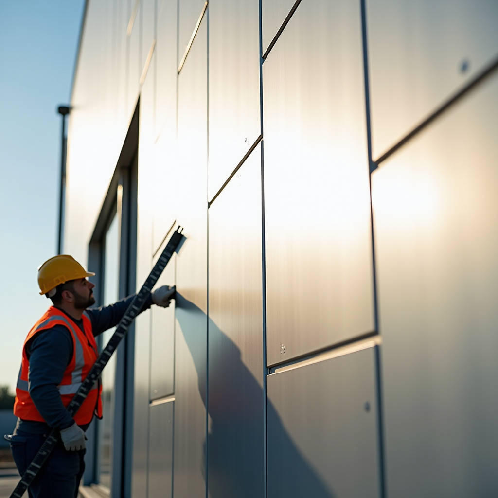
Aluminum Panel Flatness Inspection is the single most consequential quality gate between a facade that reads as crisp and professional versus one that betrays every ripple of morning light. Architects specify solid aluminium panels for their clean, monolithic appearance. General contractors budget for them expecting a premium finish. Yet when panels arrive on site with edge wave, center buckle, or the dreaded oil-canning effect, the entire project team faces a cascade of rework, finger-pointing, and schedule delays that no one budgeted for. Getting flatness right is not about having a checklist in a binder somewhere. It is about understanding what flatness actually means for solid aluminium sheets in the 2.0mm to 3.0mm thickness range, knowing which tolerances apply to which panel size, and having a defensible inspection protocol that catches problems before panels go up on the building.
What Flatness Means for Solid Aluminium Panels
Flatness in the context of solid aluminium cladding panels is the deviation of the panel surface from a true plane when the panel rests freely on a flat reference surface. Unlike aluminium composite panels, which rely on a polyethylene core to maintain stiffness, solid aluminium sheets in 2.0mm, 2.5mm, and 3.0mm thicknesses derive their flatness entirely from the base metal, the rolling process, and the post-fabrication handling. A 2.5mm solid panel spanning 1,200mm by 3,000mm has no internal dampening layer. Every residual stress from the rolling mill, every heat input from welding stiffeners, and every uneven cooling cycle during PVDF coating will express itself on the visible face.
The industry measures flatness as the maximum gap between the panel surface and a reference plane, typically expressed in millimeters per linear meter or as a percentage of the panel dimension. For architectural solid aluminium panels, the commonly referenced tolerance is 0.5% of the diagonal measurement, though this number shifts depending on whether the spec references ASTM, EN, or a proprietary manufacturer standard. What matters on site is not the number in a PDF but whether the panel looks flat under grazing light at a 10-meter viewing distance.
Oil-Canning: The Problem No One Wants to Discuss at the Kickoff Meeting
Oil-canning is the visible waviness or rippling that appears on flat metal panels under certain lighting conditions. It is not a structural failure. It does not mean the panel will leak or fall off the building. But it is the number one source of aesthetic disputes on solid aluminium facade projects. The term comes from the sound and motion of an old oil can bottom flexing in and out, and it describes exactly what happens when a thin-gauge metal panel develops elastic buckling under compressive stress.
Solid aluminium panels between 2.0mm and 3.0mm are particularly susceptible to oil-canning because the panel width-to-thickness ratio creates a large, unsupported flat area. A 2.0mm panel at 1,500mm width has a width-to-thickness ratio of 750:1. Even with properly engineered stiffeners on the reverse side, the panel face between stiffener lines can exhibit micro-waviness that becomes visible under specular reflection. The Aluminum Panel Flatness Inspection process must explicitly address oil-canning because standard flatness measurements taken with a feeler gauge and straightedge often miss the shallow, long-wave undulations that characterize oil-canning.
There is no ASTM or EN standard that defines acceptable oil-canning for architectural metal panels. The American Architectural Manufacturers Association (AAMA) has published technical papers on the subject, but the determination remains largely visual and subjective. The most defensible approach is to establish a mock-up panel under the project's actual lighting conditions and have the architect, contractor, and fabricator sign off on an acceptable range of waviness before production begins.
Flatness Tolerances by Panel Grade and Thickness
Not all solid aluminium panels are produced to the same flatness standard. The aluminium plate and sheet industry recognizes several flatness grades, each with different allowable deviation limits. Understanding these grades helps procurement managers specify the right material without overpaying for flatness the project does not need, or worse, under-specifying and facing rejection at the receiving inspection.
The table below summarizes flatness tolerances for solid aluminium sheets commonly used in architectural cladding, based on ASTM B209 and industry practice for cut-to-length panels:
| Flatness Grade | Thickness Range | Maximum Deviation (Longitudinal) | Maximum Deviation (Transverse) | Typical Application |
|---|---|---|---|---|
| Commercial Flatness (CF) | 2.0mm - 3.0mm | 6mm per 1,000mm | 8mm per 1,000mm | Backup panels, concealed areas |
| Stretcher-Leveled (SL) | 2.0mm - 3.0mm | 3mm per 1,000mm | 4mm per 1,000mm | Standard architectural cladding |
| Precision-Leveled (PL) | 2.5mm - 3.0mm | 1.5mm per 1,000mm | 2mm per 1,000mm | High-spec visible facades, anodized finishes |
| Custom Tension-Leveled | 2.0mm - 3.0mm | 0.8mm per 1,000mm | 1.2mm per 1,000mm | Premium architectural, mirror-finish panels |
Stretcher-leveled flatness is the practical minimum for any solid aluminium panel that will be visible on a building facade. The stretcher-leveling process mechanically yields the sheet in tension, redistributing internal stresses so the panel lies flat after cutting. Precision-leveled and custom tension-leveled grades add cost but become necessary when the architect specifies a high-gloss PVDF coating or an anodized finish, both of which amplify every surface irregularity.
Futeng® processes solid aluminium cladding panels through multi-roller leveling lines before fabrication, targeting stretcher-leveled flatness as the baseline for all architectural orders. For projects requiring precision-leveled tolerances, additional tension-leveling passes are applied, and each panel is individually checked before it enters the coating line.
Root Causes of Flatness Deviation in Solid Aluminium Panels
Flatness problems do not appear randomly. They trace back to specific points in the material supply chain and fabrication process. Diagnosing the root cause determines whether the solution is a supplier conversation, a process adjustment, or a design change.
Residual Stress from Rolling
Aluminium plate and sheet are produced by hot rolling and cold rolling, processes that introduce non-uniform stress distributions across the material cross-section. When a fabricator cuts a large sheet into smaller panel blanks, those residual stresses are released unevenly, and the panel warps. This is why a panel that measured flat as a full sheet can develop a bow after cutting. The Aluminum Panel Flatness Inspection protocol must include a check after cutting, not just after final fabrication.
Heat Input During Welding
Solid aluminium panels require welded stiffeners on the reverse side to achieve the spanning capability needed for facade applications. Each weld bead introduces localized heat that creates thermal expansion and contraction, pulling the panel face out of flat. The distortion is proportional to the weld size, the spacing between stiffeners, and the panel thickness. A 2.0mm panel will distort more from the same weld than a 3.0mm panel. Fabricators mitigate this through stitch welding, back-step welding sequences, and post-weld stress relief, but some distortion is inevitable. The inspection protocol must account for the fact that flatness after welding will be worse than flatness before welding, and the tolerance should reflect what is achievable with proper fabrication technique.
PVDF Coating Cure Cycles
Architectural solid aluminium panels receive a PVDF fluoropolymer coating system, typically a primer plus color coat plus clear coat, with each layer cured at temperatures around 230°C to 250°C. The panel goes through this thermal cycle multiple times. If the panel is not properly supported during curing, or if the heating and cooling rates are uneven across the panel surface, the coating process can introduce or amplify waviness. The Aluminum Association publishes guidelines on thermal effects during coating, and experienced coaters understand that racking orientation and oven airflow patterns directly affect final flatness.
Handling and Transportation
Even a perfectly flat panel leaving the factory can arrive on site with a twist or bow if it was improperly handled. Solid aluminium panels in the 2.0mm to 3.0mm range are stiff enough to support their own weight when properly crated but flexible enough to take a permanent set if stored on uneven dunnage or lifted with a single-point sling. The inspection protocol must include a receiving inspection at the job site, not just a factory inspection at the fabricator's facility.
Inspection Methods and Tools for Site and Factory
The tools for Aluminum Panel Flatness Inspection range from simple mechanical gauges to laser scanning systems. The choice depends on whether the inspection is happening at the fabricator's quality control station, at the receiving dock, or after installation.
Straightedge and Feeler Gauge
The most widely used method combines a calibrated straightedge with a set of feeler gauges. The straightedge is placed across the panel surface in multiple orientations, and the inspector slides feeler gauges under the straightedge to measure the maximum gap. This method is specified in ASTM B209 for sheet flatness and works well for detecting short-wavelength deviations like edge wave and center buckle. Its limitation is that it does not capture long-wavelength oil-canning, which may have a gap too shallow to measure but a wave period long enough to catch light.
Dial Indicator on a Granite Surface Plate
For smaller panels or for benchmark measurements, placing the panel on a certified granite surface plate and running a dial indicator across the surface provides a quantitative flatness map. This method is common in precision machining but less practical for full-size architectural panels that may measure 1,500mm by 4,000mm.
Laser Scanning and Digital Flatness Mapping
3D laser scanning systems can capture the entire panel surface as a point cloud and generate a color-coded deviation map. This method is fast, objective, and produces documentation that can be shared with architects and owners. The ISO 12781 standard provides a framework for areal surface texture measurement that can be adapted to panel flatness. For large-scale projects with hundreds of panels, laser scanning at the factory provides a defensible quality record before panels ship.
Visual Inspection Under Grazing Light
For oil-canning specifically, the most practical inspection method is visual assessment under controlled lighting. The panel is positioned vertically or at the angle it will be installed, and a light source is directed across the surface at a shallow angle, typically 5 to 15 degrees from the panel plane. Any waviness becomes immediately visible as alternating light and dark bands. The industry best practice is to conduct this inspection at a distance of 3 to 5 meters, which approximates the viewing distance from the ground for a typical building facade. The Metal Construction Association (MCA) has published a white paper on visual inspection methodology for metal wall panels that provides a useful framework for establishing project-specific acceptance criteria.
Building a Defensible Inspection Protocol
A defensible Aluminum Panel Flatness Inspection protocol is one that survives a dispute. When the architect rejects panels and the fabricator insists they meet spec, the difference between a resolved issue and a legal claim is whether the acceptance criteria were documented, communicated, and agreed upon before production.
The protocol should define the following elements in writing:
- Applicable standard and flatness grade: Reference ASTM B209, EN 485, or a specific manufacturer standard, and state the flatness grade clearly.
- Measurement method: Specify whether flatness is measured with a straightedge and feeler gauge, a dial indicator, or a laser scanner. Include the orientation of measurements (longitudinal, transverse, diagonal).
- Acceptance thresholds: State the maximum allowable deviation in millimeters per meter or as a percentage of panel dimension. For oil-canning, define the lighting conditions and viewing distance for visual assessment.
- Sampling plan: Define whether every panel is inspected or a statistical sample per AQL (Acceptable Quality Limit) methodology. For high-spec architectural projects, 100% inspection of visible panels is common.
- Inspection timing: Specify inspection points: after cutting, after welding, after coating, at receiving, and after installation.
- Documentation: Define the inspection report format, including panel identification, measurement values, inspector name, date, and pass/fail determination.
A protocol that exists only in a specification document is not a protocol. It becomes a protocol when the inspector has the tools, the training, and the authority to stop non-conforming panels from progressing to the next stage.
Flatness and Coating Selection: The Interaction Effect
Coating choice and flatness are not independent decisions. A flatness deviation that is invisible under a matte PVDF finish may be glaringly obvious under a high-gloss or metallic coating. The specular reflection from a gloss surface amplifies surface waviness by creating a mirror-like reflection that distorts and draws the eye to any irregularity.
For solid aluminium panels with a 60-degree gloss rating above 70 GU, the flatness tolerance should be tightened by approximately 30% to 50% compared to a matte finish with a gloss rating below 30 GU. This means a panel that would pass at 3mm per 1,000mm deviation under a matte coating may need to hold 1.5mm to 2.0mm per 1,000mm under a high-gloss coating to achieve the same visual quality.
Anodized finishes present an even greater challenge. Anodizing is a transparent oxide layer that grows from the aluminium surface itself, meaning it preserves and can even accentuate the underlying metal texture. Any flatness deviation, scratch, or surface blemish that exists before anodizing will be visible after anodizing. For anodized solid aluminium panels, precision-leveled flatness is not optional; it is the minimum starting point.
Stiffener Design and Its Impact on Flatness
The reverse-side stiffener grid is the primary engineering control for flatness in solid aluminium panels. Stiffeners are typically aluminium extrusions or formed profiles bonded or welded to the panel back, and their spacing, cross-section, and attachment method directly determine the panel's resistance to oil-canning and wind-induced deflection.
Key stiffener design parameters that affect flatness:
- Stiffener spacing: Closer stiffener spacing reduces the unsupported panel area and improves flatness, but adds weight and cost. A spacing of 400mm to 600mm center-to-center is common for 2.5mm and 3.0mm panels.
- Stiffener cross-section: A hat-section or channel stiffener provides greater bending stiffness than a flat bar of the same weight, improving flatness without adding material cost.
- Attachment method: Welded stiffeners provide a rigid connection that constrains panel movement but introduce heat distortion. Adhesive-bonded stiffeners eliminate heat distortion but rely on the adhesive's long-term durability. The trade-off must be evaluated for each project's climate and service life requirements.
- Perimeter stiffeners: Panels without edge stiffening are prone to edge wave, where the free edge of the panel curls or ripples. A continuous perimeter stiffener or a folded return edge significantly improves edge flatness.
Receiving Inspection: The Last Line of Defense
The receiving inspection at the job site is the point where the contractor has maximum leverage. Once panels are installed, the cost of removal and replacement dwarfs the cost of rejection at the receiving dock. A thorough receiving inspection for flatness should include:
Random sampling of panels from each crate, with the sample size determined by the project's AQL. Each sampled panel is laid on a flat, clean surface and checked with a straightedge in at least three orientations: longitudinal, transverse, and both diagonals. The measured gaps are recorded and compared against the acceptance criteria. Panels are also visually inspected under available lighting for oil-canning, with the understanding that site lighting may not replicate the final installed conditions.
Panels that fail the receiving inspection should be documented with photographs, measurement data, and panel identification numbers. The contractor should notify the fabricator immediately and agree on a disposition: rework, replacement, or acceptance with concession. A concession should always be documented in writing and signed by the architect, as an accepted deviation today can become a rejected installation tomorrow if the project team changes.
Post-Installation Inspection and the Mock-Up Reference
Flatness inspection does not end when panels are installed. The installed panel is subject to loads, thermal movement, and attachment constraints that can alter its flatness relative to the free state. Post-installation inspection should compare the installed panel appearance to the approved mock-up under similar lighting conditions.
The mock-up is the single most powerful tool for managing flatness expectations. A properly executed mock-up, built at the job site using production panels and the actual installation system, establishes a visual reference that all parties have accepted. When a dispute arises about whether an installed panel is acceptably flat, the question is not "does it meet the spec?" but "does it look as good as the mock-up?" The mock-up shifts the conversation from abstract numbers to a concrete visual standard.
For projects where a full-scale mock-up is not practical, a panel flatness reference sample can serve a similar function. The reference sample is a panel that the architect, contractor, and fabricator have jointly inspected and approved as representing the acceptable limit of flatness deviation. Production panels that are flatter than the reference sample pass; panels that are worse fail.
Aluminum Panel Flatness Inspection, when executed with technical rigor and documented thoroughly, transforms a subjective aesthetic judgment into an objective quality control process. The goal is not to eliminate every micron of deviation. Solid aluminium panels are metal products, not optical flats, and some variation is inherent in the material and the fabrication process. The goal is to establish clear, measurable, agreed-upon standards that ensure the finished facade meets the architect's design intent and the owner's expectations, without surprises, delays, or disputes.