Aluminum Anodize Thickness Measurement for Solid Cladding Panels A Practical Engineering Guide
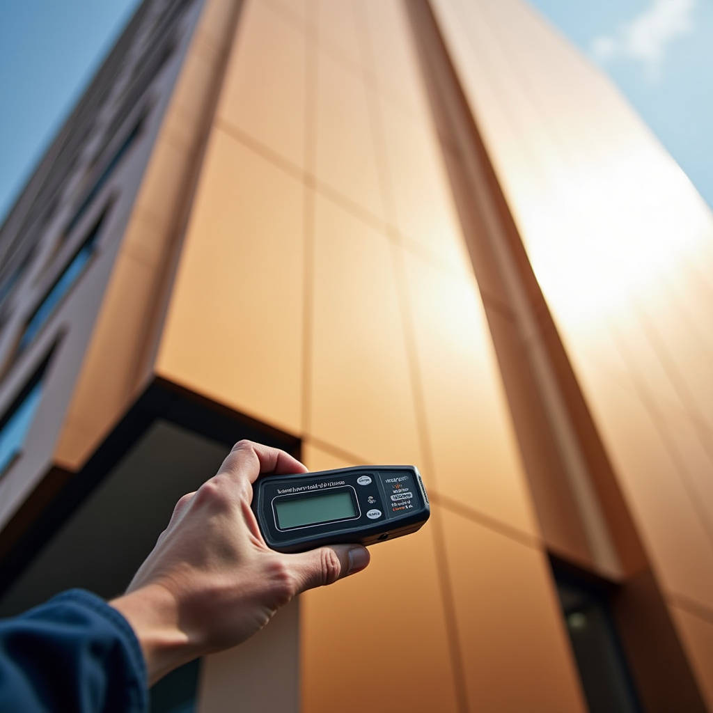
Getting the anodized layer thickness right on architectural aluminum is not a cosmetic afterthought. It determines whether a 3.0mm solid panel on a 40-story curtain wall will look uniform at 4:00 PM on a sunny afternoon, or whether it will show patchy iridescence that the facade consultant flags immediately. Aluminum Anodize Thickness Measurement sits at the intersection of quality assurance, corrosion science, and contractual compliance. Too thin, and the oxide layer fails salt spray testing. Too thick, and you risk crazing on formed edges. The measurement itself is deceptively simple in principle but full of traps in practice: substrate alloy, surface roughness, edge geometry, and even ambient temperature all nudge the readings. This article unpacks what actually matters when specifying, measuring, and verifying anodic coating thickness on solid aluminum cladding panels, drawing on ASTM B244, ISO 2360, and field experience from projects across the Middle East, Southeast Asia, and North America.
Why Anodize Thickness Matters for Solid Aluminum Cladding
Anodizing is a conversion coating. Unlike PVDF liquid spray or powder coat, which deposit material onto the aluminum surface, anodizing grows an aluminum oxide layer from the substrate itself. Roughly two-thirds of the measured thickness grows outward from the original surface, and one-third penetrates inward. This matters for architectural panels because the dimensional change is not simply additive. A 20µm anodic layer does not add 20µm to the panel thickness. The net build-up is closer to 13–14µm above the original surface.
For solid aluminum cladding panels, typically specified at 2.0mm, 2.5mm, or 3.0mm base thickness per ASTM B209, the anodic layer represents a tiny fraction of total thickness. But on visible surfaces spanning 4-meter bays, even subtle variations in oxide thickness produce visible color shifts. The human eye is remarkably sensitive to reflectance differences on large flat planes. A 5µm thickness variation across a panel can shift the perceived hue of architectural anodizing enough to trigger a rejection from the architect's quality control team.
Corrosion resistance is the other half of the equation. Type II architectural anodizing (Class I per AAMA 611) targets a minimum of 17–18µm on exterior surfaces. Drop below 15µm, and you start losing the barrier properties that protect the underlying aluminum from pitting in coastal or industrial atmospheres. The measurement is not academic. It is the difference between a facade that looks pristine after 15 years and one that shows white filiform corrosion creeping from the edges by year five.
How Anodizing Changes Panel Dimensions: The Growth Ratio
Anodizing converts aluminum metal into aluminum oxide (Al₂O₃). The oxide occupies more volume than the metal it replaces, but not all of that volume appears above the original surface. The commonly cited growth ratio is approximately 1:1.5 to 1:2.0, depending on alloy and anodizing conditions. For 6063-T6 architectural extrusions, a good working number is that the anodic layer penetrates about 50% and builds up about 50%. For 5005 and 5052 sheet alloys used in solid aluminum cladding, the ratio skews slightly toward more build-up, roughly 40% penetration and 60% build-up.
Practically speaking, if you specify 20µm of Type II anodizing on a 2.5mm 5052-H32 solid aluminum panel, the finished panel will measure approximately 2.512mm total thickness. The anodic layer consumed about 8µm of the original aluminum and added about 12µm above the original surface. This is well within the ±0.08mm thickness tolerance typical for 2.5mm aluminum sheet, so no dimensional adjustment is needed in most cases. But for hard anodizing (Type III) at 50µm or more, the net build-up can reach 30µm per side, which starts to matter for interlocking panel joints and gasket compression.
Key engineering note: For solid aluminum cladding panels with Type II anodizing below 25µm, the dimensional change is typically absorbed within standard mill tolerances. No special drawing adjustments are required. For Type III hard anodizing above 40µm, consult the panel fabricator about joint clearances.
Measurement Methods: Eddy Current, Microscopy, and the Real World
Aluminum Anodize Thickness Measurement in production environments relies overwhelmingly on the eddy current principle. The anodic layer is electrically non-conductive aluminum oxide sitting on a conductive aluminum substrate. An eddy current probe generates a high-frequency alternating magnetic field that induces eddy currents in the base metal. The strength of those currents depends on the distance between the probe and the conductive substrate, i.e., the coating thickness. This is the method standardized in ASTM B244 and ISO 2360.
Eddy current instruments from manufacturers like DeFelsko (PosiTector 6000 series) and Fischer (DualScope) are the workhorses of architectural aluminum quality control. They are handheld, battery-powered, and deliver readings in seconds with ±1µm accuracy on properly calibrated setups. But the "properly calibrated" part is where things go wrong on job sites.
The substrate matters enormously. Eddy current instruments must be zeroed on bare, uncoated aluminum of the same alloy and surface finish as the production panels. If you calibrate on a polished 6063 extrusion and then measure a mill-finish 5052 sheet, the readings will be off by 2–4µm because the surface roughness changes the probe-to-metal coupling. This is a common failure mode on construction sites where the inspector calibrates on whatever bare aluminum is handy and then measures the installed panels.
Surface curvature introduces another error source. On formed panel returns, corners, and folded edges, the probe cannot sit flat. The air gap between the probe and the coating surface reduces the eddy current coupling, producing falsely low readings. ASTM B244 explicitly warns that measurements on curved surfaces require special calibration using the same radius. For architectural panels with 90-degree returns, the flat face is the only reliable measurement location.
Cross-Sectional Microscopy: The Referee Method
When there is a dispute, cross-sectional microscopy per ASTM B487 is the referee. A small coupon is cut from the panel, mounted in epoxy, polished perpendicular to the surface, and examined under a metallurgical microscope at 500× to 1000× magnification. The anodic layer appears as a distinct band with a different optical character from the aluminum substrate. A calibrated eyepiece or image analysis software measures the thickness directly.
This method is destructive, slow, and requires a laboratory. It is not practical for production QC. But it is the gold standard for verifying that eddy current instruments are reading correctly on a given alloy and surface finish. For critical architectural projects, especially those with 10-year facade warranties, Futeng® and other reputable fabricators maintain cross-section records for each alloy batch to validate their eddy current measurements.
ASTM B244 and ISO 2360: What the Standards Actually Require
ASTM B244, "Standard Test Method for Measurement of Thickness of Anodic Coatings on Aluminum and of Other Nonconductive Coatings on Nonmagnetic Basis Metals with Eddy-Current Instruments," is the governing document in North America and much of the Middle East. ISO 2360 serves the same role in Europe and Asia. The two standards are technically similar but not identical in their calibration requirements and acceptance criteria.
Under ASTM B244, the instrument must be calibrated using certified thickness standards traceable to a national metrology institute. The calibration standards should have a nonconductive coating on a nonmagnetic metal substrate that approximates the electrical properties of the aluminum being measured. The standard requires at least two calibration points bracketing the expected measurement range. For architectural anodizing in the 15–25µm range, this typically means calibration at 10µm and 50µm.
Measurement procedure per ASTM B244:
- Verify calibration on the reference standard immediately before and after each measurement session
- Take a minimum of five readings per measurement area, discarding any obvious outliers
- Space readings at least 25mm apart to avoid edge effects
- Stay at least 25mm from any edge, cutout, or fastener hole
- Report the arithmetic mean of the valid readings
- If the standard deviation exceeds 10% of the mean, investigate the cause
ISO 2360 adds a requirement for temperature compensation when measuring at ambient temperatures outside 20±5°C. This is relevant for site measurements in the Gulf region, where ambient temperatures of 45°C are common and can shift eddy current readings by 1–2µm if uncompensated.
The acceptance criteria depend on the specification. AAMA 611 (Voluntary Specification for Anodized Architectural Aluminum) requires Class I architectural anodic coatings to have a minimum thickness of 17µm (0.7 mils) on exterior surfaces. The specification also requires that no single reading fall below 80% of the specified minimum, i.e., no reading below 13.6µm for Class I. This is a stricter requirement than simply averaging above 17µm.
Common Measurement Errors and How to Avoid Them
After auditing dozens of facade projects, certain failure patterns repeat. Here are the most expensive ones:
Wrong substrate calibration. The inspector calibrates on a 6063-T6 extrusion sample and then measures 5052-H32 sheet panels. The electrical conductivity of 5052 is roughly 35% IACS versus 50%+ for 6063. The eddy current response differs enough to introduce a 2–5µm systematic error. Always calibrate on the same alloy and temper as the production material.
Edge effect. Eddy currents spread laterally in the substrate. When the probe is within about 25mm of an edge, the current paths are truncated, reducing the signal and producing a falsely low reading. This is a particular problem on narrow panel returns and small trim pieces. The solution is to measure only on surfaces large enough to accommodate the probe's full field, or to use a probe with a smaller measurement area and recalibrate for the specific geometry.
Surface roughness mismatch. A mill-finish panel has a surface roughness (Ra) of 0.5–1.5µm. An etched and desmutted surface before anodizing might have Ra of 2–4µm. The probe sits on the peaks of the roughness profile, measuring the coating thickness at those points. The valleys are thicker. The eddy current reading represents something close to the mean coating thickness, but the roughness reduces the effective probe contact area. Calibration must be on a surface with the same roughness as the production panels.
Probe wear. Eddy current probes have a hard-faced tip, but after thousands of measurements on architectural aluminum, the tip wears. A worn probe tip changes the probe-to-surface coupling and introduces drift. The probe should be checked against the calibration standard at the start of every shift, and replaced when readings drift beyond the instrument's stated accuracy.
Temperature effects. Aluminum conductivity changes with temperature, approximately 0.4% per °C. A 20°C temperature difference between calibration and measurement shifts the reading by roughly 0.5–1.0µm in the 20µm range. This is borderline significant for architectural QC. Instruments with automatic temperature compensation are preferred for field use.
Type II vs. Type III Anodizing: Thickness Ranges and Measurement Considerations
Architectural cladding almost exclusively uses Type II (sulfuric acid) anodizing per MIL-A-8625 or AAMA 611. The thickness range for Class I exterior applications is 17–25µm. Below 17µm, corrosion resistance drops off. Above 25µm, the oxide layer becomes more brittle and prone to micro-cracking on formed edges, which is a problem for panels with folded returns.
Type III (hard anodizing) is rare on architectural cladding panels but appears on entrance doors, louver blades, and high-traffic interior panels where abrasion resistance matters. Type III thickness ranges from 25µm to 100µm, with 50µm being a common specification. The measurement challenges are different. The thicker oxide layer is harder and more uniform, which actually makes eddy current measurement more repeatable. But the dimensional change is significant enough that panel fabrication drawings must account for it.
| Parameter | Type II Class I (Architectural) | Type II Class II (Interior) | Type III (Hard Anodizing) |
|---|---|---|---|
| Thickness Range | 17–25 µm | 10–17 µm | 25–100 µm |
| Typical Specification | 20 µm (AAMA 611) | 12 µm | 50 µm |
| Measurement Method | Eddy Current (ASTM B244) | Eddy Current (ASTM B244) | Eddy Current + Microscopy |
| Net Build-Up per Side | ~10–15 µm | ~6–10 µm | ~25–60 µm |
| Impact on 3.0mm Panel | Negligible (within tolerance) | Negligible | Requires joint adjustment |
| Single-Point Minimum | 13.6 µm (80% of 17) | 8 µm (80% of 10) | 80% of specified minimum |
| Sealing Requirement | Required (AAMA 611) | Optional | Optional (sealed or unsealed) |
| Typical Architectural Use | Exterior cladding, curtain wall | Interior trim, soffits | Doors, louvers, high-wear surfaces |
Quality Control Protocol for Anodized Solid Aluminum Panels
A defensible QC protocol for Aluminum Anodize Thickness Measurement on solid aluminum cladding panels should cover three stages: incoming material verification, in-process control, and final inspection. The following protocol is based on AAMA 611, ASTM B244, and practical experience on projects where facade consultants demanded full traceability.
Stage 1: Incoming Material Verification
Before anodizing, verify the alloy and temper of the aluminum sheet against the mill certificate. Measure the base metal thickness at multiple points per ASTM B209 tolerances. Record the surface roughness (Ra) of the as-received material. This establishes the baseline for later calibration. For 5005-H14 or 5052-H32 solid aluminum sheet at 2.0mm, 2.5mm, or 3.0mm, the thickness tolerance is typically ±0.08mm for 2.0mm and ±0.10mm for 3.0mm.
Stage 2: In-Process Control
After anodizing and sealing, measure the anodic coating thickness on a statistically representative sample from each anodizing batch. For architectural cladding, a common sampling plan is one panel per rack, with five measurement points per panel (four corners and center). Record all individual readings, not just the average. The data should be plotted on a control chart to detect process drift before it produces out-of-specification material.
Stage 3: Final Inspection
Final inspection includes 100% visual inspection for color uniformity, sealing quality (per ASTM B136 dye stain test), and coating thickness measurement on a sampling basis. The sampling frequency should be agreed with the project specifier before production begins. A typical requirement is one measurement per 10m² of panel area, with a minimum of five measurements per panel size. All measurements must be documented and traceable to the panel identification number.
For projects requiring third-party verification, the fabricator should arrange for an independent testing laboratory to perform cross-sectional microscopy on witness coupons per ASTM B487. The witness coupons should be anodized in the same batch as the production panels. This provides an independent check on the eddy current measurements and is often required for warranty validation.
Sealing Quality and Its Relationship to Thickness Measurement
Anodize thickness is necessary but not sufficient for corrosion protection. The anodic layer is porous. The pores must be sealed by hydration in hot deionized water or a nickel acetate solution to convert the amorphous aluminum oxide to a hydrated crystalline form (boehmite) that swells and closes the pores. An unsealed or poorly sealed 20µm anodic coating will perform worse in corrosion testing than a properly sealed 15µm coating.
The relationship between thickness measurement and sealing quality is important because eddy current instruments cannot distinguish sealed from unsealed coatings. The instrument measures total coating thickness regardless of pore condition. A panel can pass thickness measurement with flying colors and still fail the AAMA 611 sealing test (ASTM B136 modified dye stain). The QC protocol must include both measurements.
Sealing quality is typically verified by the dye stain test (ASTM B136), the acid dissolution test (ASTM B680), or the admittance test (ISO 2931). The dye stain test is the most common for architectural applications. A drop of nitric acid is applied to the surface, followed by a dye solution. If the anodic coating is properly sealed, the dye wipes off without staining. If it is under-sealed, the dye penetrates and leaves a visible stain.
For solid aluminum cladding panels on coastal projects, where salt-laden air accelerates corrosion, specifying both a minimum anodic thickness (20µm) and a maximum admittance value (ISO 2931) provides a more robust quality assurance framework than thickness alone. Some facade consultants now require both measurements on the same statistical sample.
Field Verification: Measuring Installed Panels
Aluminum Anodize Thickness Measurement does not end at the factory gate. On major projects, the facade consultant or owner's representative often conducts field verification of installed panels. This presents challenges that do not exist in the factory.
Access is the first problem. Panels installed at height require boom lifts or scaffolding. The inspector must carry the instrument, calibration standards, and documentation to the measurement location. Eddy current instruments are well-suited to this because they are portable and battery-operated, but the calibration standards must be protected from damage and contamination.
Surface contamination is the second problem. Installed panels accumulate construction dust, sealant residue, and atmospheric deposits. The measurement surface must be cleaned with a mild detergent and water, then dried, before measurement. Solvents should be avoided because they can leave residues that affect the probe coupling.
Temperature is the third problem. Panels in direct sunlight on a hot day can reach 60°C or more. The eddy current reading will be shifted by the temperature effect on aluminum conductivity. The instrument should be allowed to equilibrate to the panel temperature, and the calibration should be checked on a reference standard at the same temperature. If the instrument does not have automatic temperature compensation, the readings should be corrected using the manufacturer's temperature coefficient.
Field measurements are typically less precise than laboratory measurements. A realistic expectation for field measurement uncertainty is ±2–3µm, compared to ±1µm in a controlled environment. The acceptance criteria should account for this. If the specification requires a minimum of 17µm and the field measurement reads 15.5µm, the panel should not be automatically rejected. Instead, a cross-sectional measurement on a removed sample should be the referee.
Specifying Anodize Thickness: What to Put on the Drawing
Architectural specifications for anodized solid aluminum cladding panels should reference the applicable standards and state the minimum thickness clearly. A poorly written specification creates ambiguity that leads to disputes. A well-written specification eliminates interpretation problems.
Recommended specification language for Type II architectural anodizing on exterior solid aluminum cladding panels:
"Anodizing shall be Type II, Class I per AAMA 611. Minimum anodic coating thickness shall be 20µm (0.8 mils) on all exterior surfaces, measured per ASTM B244 using eddy current instruments calibrated on the same alloy and surface finish as the production panels. No single reading shall be less than 16µm (80% of specified minimum). Sealing shall be verified by ASTM B136 modified dye stain test. Coating thickness measurement records shall be submitted for each production batch."
For projects in corrosive environments (coastal, industrial), consider specifying 25µm minimum thickness. The additional 5µm adds approximately 15–20% to the anodizing cost but significantly extends the service life in aggressive atmospheres.
For interior panels (soffits, column covers, interior wall cladding), Class II anodizing at 12µm minimum is typically adequate. The cost saving is modest, so many projects standardize on Class I for all panels to avoid mix-ups during installation.
The Cost of Getting It Wrong
Incorrect Aluminum Anodize Thickness Measurement has real financial consequences. The most common scenario is an under-thickness batch that passes factory QC because the instrument was calibrated on the wrong substrate, then gets flagged during field verification. The panels are already installed. The options are: remove and replace (costly), accept with a discount (reputational damage), or apply a clear organic coating over the anodizing as a remedial measure (compromise). None of these are good outcomes.
A less obvious cost is over-thickness. Anodizing to 30µm when 20µm is specified wastes energy, chemicals, and time. The anodizing bath operates at a fixed current density, and coating thickness is proportional to time. Every extra micron adds roughly 2–3 minutes to the anodizing cycle. For a production line running 500 panels per day, over-anodizing by 5µm adds hours of unnecessary processing time and increases the risk of edge crazing on formed panels.
The cost of proper measurement equipment is trivial compared to the cost of a single rejected batch. A quality eddy current thickness gauge with data logging capability costs $2,000–$4,000. A single rejected panel on a high-rise facade, including access equipment, labor, and schedule delay, can cost $5,000–$15,000 to replace. The arithmetic is straightforward.
For procurement managers sourcing solid aluminum cladding panels internationally, verifying the fabricator's measurement capability should be part of the factory audit. Ask to see the calibration certificates for their thickness gauges, their control charts for anodizing thickness, and their cross-sectional microscopy records. A fabricator that cannot produce these documents is not in control of their process. Suppliers like Futeng®, who specialize in solid aluminum cladding for export markets, maintain full measurement traceability as a standard practice because international facade consultants demand it.
Emerging Technologies and Future Directions
Eddy current measurement of anodic coatings has been fundamentally unchanged for decades, but incremental improvements are making the technology more reliable. Modern instruments with automatic substrate recognition, temperature compensation, and Bluetooth data logging reduce operator error. Some instruments now store calibration curves for multiple alloys, allowing the inspector to switch between 5005 and 6063 with a menu selection rather than a full recalibration.
Optical coherence tomography (OCT) is an emerging non-destructive technique that can measure anodic coating thickness with sub-micron resolution without contact. Originally developed for medical imaging, OCT uses near-infrared light to create cross-sectional images of layered structures. It can distinguish the anodic layer from the aluminum substrate and measure thickness directly. The technology is currently expensive and not field-portable, but it may become practical for laboratory QC within the next decade.
For the foreseeable future, the eddy current method standardized in ASTM B244 and ISO 2360 will remain the industry workhorse. The key to reliable measurement is not the instrument technology but the discipline of the operator: calibrate on the right substrate, measure on flat surfaces away from edges, verify calibration before and after each session, and document everything. These are simple practices, but they are violated on construction sites every day.
The architectural aluminum industry has a saying: "You cannot manage what you do not measure." For anodized solid aluminum cladding, the measurement is not just about compliance. It is about confidence that the panels on the building will look right and last. The 20µm of aluminum oxide between the metal and the atmosphere is doing a lot of work. Measuring it properly is the least the industry can do to respect that.