Aluminum Coating Color Difference Check Engineering Protocols for Solid Panel Facades
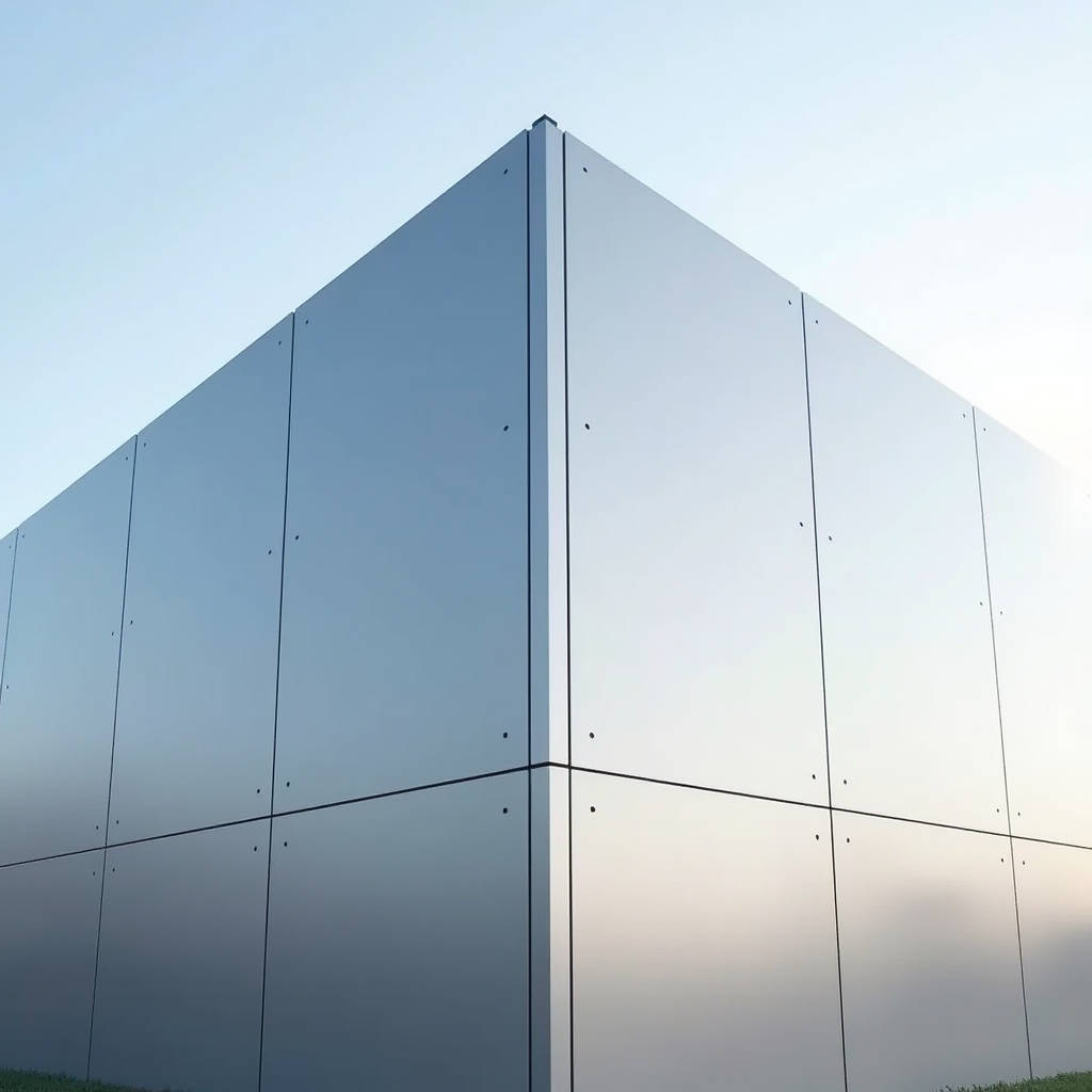
On a large-scale commercial facade, a 2-degree shift in panel orientation can make two identically coated aluminum sheets look like they came from different production batches. This is the reality that facade engineers and procurement managers face when dealing with solid aluminum cladding panels. An Aluminum Coating Color Difference Check is not a single inspection step performed at the factory gate. It is a systematic verification process that spans alloy selection, coating application parameters, on-site installation geometry, and long-term weathering behavior. When a $15 million curtain wall project hangs on the visual uniformity of 3,000 square meters of PVDF-coated solid aluminum sheets, the tolerance for "close enough" evaporates. This article unpacks the technical layers behind color consistency verification, moving beyond basic colorimeter readings into the engineering decisions that determine whether a building facade reads as a cohesive surface or a patchwork of mismatched panels.
Why Color Difference on Solid Aluminum Panels Is an Engineering Problem, Not a Cosmetic Afterthought
Color variation on architectural aluminum cladding is often misclassified as a minor aesthetic issue. In practice, it is a material science and process control challenge with direct contractual and financial consequences. A single rejected batch of 2.5mm solid aluminum panels with PVDF coating can delay a project by 6 to 10 weeks, triggering liquidated damages clauses and cascading schedule disruptions. The root causes of color deviation span three domains: substrate metallurgy, coating chemistry, and installation physics. Each domain introduces its own variables, and the cumulative effect of small deviations across all three can produce a visible mismatch that no amount of on-site adjustment can fix.
The aluminum alloy itself matters. Alloy 3003 and 5052, the two most common grades for solid aluminum cladding, respond differently to pretreatment chemicals. The manganese content in 3003 can produce a slightly different surface tone after chromate conversion coating compared to the magnesium-rich 5052. When a fabricator switches alloy grades mid-project without adjusting pretreatment parameters, the resulting color shift under PVDF topcoats can measure ΔE > 1.5, which exceeds the typical specification threshold of ΔE ≤ 1.0. This is why an Aluminum Coating Color Difference Check must begin with alloy traceability, not with a spectrophotometer.
The Three-Layer Structure of PVDF Coating and Its Impact on Color Consistency
Architectural PVDF coatings on solid aluminum panels follow a three-layer system defined by AAMA 2605: a primer layer (5-8 microns), a color coat (20-25 microns), and a clear topcoat (12-15 microns). Each layer contributes to the final perceived color in ways that single-layer measurement cannot capture. The primer influences adhesion and corrosion resistance but also affects the brightness of the color coat through its reflectivity. A primer applied 2 microns too thick can shift the perceived lightness (L* value) of the finished panel by 0.5 to 0.8 points.
The color coat is where the pigment resides, and here the variables multiply. Pigment dispersion quality, solvent evaporation rate during flash-off, and oven temperature profile all affect the final hue. A temperature difference of 8°C across a curing oven can produce a visible gloss variation between panels processed at the same time. The clear topcoat, while transparent, has a refractive index that interacts with the color coat beneath it. Variations in clear coat thickness alter how light enters and reflects from the pigment layer, shifting the perceived color under different viewing angles — a phenomenon known as metamerism.
| Coating Parameter | Specification Range | Impact on ΔE if Out of Spec | Detection Method |
|---|---|---|---|
| Primer thickness | 5-8 microns | ΔE +0.5 to 0.8 (lightness shift) | Eddy current gauge per ISO 2360 |
| Color coat thickness | 20-25 microns | ΔE +1.0 to 2.5 (hue + chroma shift) | Cross-section microscopy or eddy current |
| Clear coat thickness | 12-15 microns | ΔE +0.3 to 0.6 (gloss + metamerism) | Eddy current gauge; visual under D65 light |
| Oven curing temperature | 232-249°C (peak metal temp) | ΔE +0.8 to 1.5 (gloss + color) | Temperature data loggers on conveyor |
| Pigment dispersion | Hegman gauge ≥ 7 | ΔE +0.5 to 1.2 (uneven color) | Drawdown test + spectrophotometer |
| Substrate alloy | 3003 or 5052 (consistent per project) | ΔE +0.3 to 1.0 (pretreatment tone) | XRF analyzer or mill cert verification |
Color Measurement Standards: What ΔE Values Actually Mean for Facade Projects
The industry standard for quantifying color difference is the CIELAB color space, expressed as ΔE (delta E). A ΔE value of 1.0 is generally accepted as the threshold of perceptibility for the human eye under controlled lighting. However, this threshold is not uniform across all color regions. The human eye is more sensitive to differences in the orange and yellow spectrum than in blue or green. A ΔE of 0.8 in a warm grey PVDF coating may be more noticeable than a ΔE of 1.2 in a deep blue.
ASTM D2244 defines the standard practice for calculating color tolerances using CIELAB coordinates (L*, a*, b*). The formula accounts for lightness (ΔL*), red-green shift (Δa*), and yellow-blue shift (Δb*). For architectural aluminum cladding, the specification typically references ΔE*ab (CIE 1976) or the more perceptually uniform ΔE*00 (CIE 2000). The ΔE*00 formula includes weighting factors for lightness, chroma, and hue, making it more representative of human visual perception. A project specification that simply states "ΔE ≤ 1.0" without specifying which formula is being used leaves room for dispute.
"A spectrophotometer reading of ΔE = 0.9 under D65 illuminant does not guarantee that two panels will match under the mixed daylight and LED lighting of a building lobby. Color evaluation must include multiple illuminants and viewing angles." — This is standard guidance found in the ASTM D2244 standard for color difference calculation.
Anodized Aluminum Color Variation: A Different Set of Rules
Anodized finishes on solid aluminum panels introduce color control challenges that are fundamentally different from PVDF. The anodic oxide layer is translucent, not opaque. The perceived color results from the interaction of light with the aluminum substrate through the oxide film, which means the substrate's surface condition directly influences the final appearance. Alloy composition, temper, grain structure, and even the rolling direction of the aluminum sheet affect how the anodized surface looks.
For anodized solid aluminum cladding, color consistency requires batch-level control of the aluminum substrate. Panels fabricated from the same coil of aluminum, processed through the same anodizing tank at the same time, have the highest probability of matching. When panels from different coils are mixed on a facade, even if they went through the same anodizing line, color variation can be visible. The AAMA 611 specification for anodized architectural aluminum addresses this by requiring that anodized finishes be evaluated for color uniformity under natural north-sky daylight at a 90-degree viewing angle.
Temperature control in the anodizing tank is another critical variable. A temperature swing of ±2°C in the sulfuric acid electrolyte bath changes the oxide layer's pore structure, which in turn affects how the layer refracts light. The resulting color shift is subtle but real, and it accumulates across large facade areas. An Aluminum Coating Color Difference Check for anodized panels must therefore include process temperature logs, not just final color readings.
Installation Geometry and Viewing Angle: The Overlooked Variable
Even when factory color measurements show perfect consistency, panels installed on a building can appear mismatched. This is because PVDF coatings, particularly metallic and mica finishes, exhibit directional reflectance. The orientation of pigment flakes in the coating creates a "flop" effect — the color appears different when viewed from different angles. Two panels with identical spectrophotometer readings, installed at slightly different angles relative to the building plane, will reflect light differently to an observer on the ground.
The solution is not to demand tighter color tolerances from the factory, but to enforce installation tolerances that preserve the visual uniformity of the coating. Panels must be installed in a single plane with a deviation of no more than 2mm per 3-meter panel length. This requires precise substructure alignment and consistent shimming. The ISO 10545 series, while primarily for ceramic tiles, provides useful guidance on visual assessment methodology that facade engineers can adapt for aluminum cladding inspection.
Futeng® has observed on multiple international projects that color uniformity complaints from site teams are frequently traced to installation angle discrepancies rather than actual coating variation. A systematic Aluminum Coating Color Difference Check protocol should therefore include a pre-installation mockup under site lighting conditions, with panels installed at the specified plane tolerance, viewed from the expected observer distance and angle. This mockup becomes the visual reference standard for the entire facade, supplementing the numerical ΔE specification.
On-Site Inspection Protocol: Tools, Conditions, and Documentation
A defensible on-site color check requires more than a handheld colorimeter. The inspection environment, instrument calibration, sampling strategy, and documentation all affect the validity of the results. The following protocol reflects practices used on major commercial facade projects in the Middle East, Southeast Asia, and North America.
Lighting Conditions
Color evaluation must be conducted under standardized lighting. Natural north-sky daylight between 10:00 AM and 2:00 PM (in the northern hemisphere) provides the most consistent conditions. When this is not available, a D65 (6500K) light booth should be used. Mixed lighting — such as partial shade from scaffolding or adjacent buildings — invalidates the reading. The inspector must document the lighting conditions, including cloud cover and time of day, alongside each measurement.
Instrument Selection and Calibration
A sphere-based spectrophotometer with a minimum of 8mm measurement aperture is the minimum acceptable instrument for architectural aluminum color measurement. 45°/0° geometry instruments can be used for solid colors, but sphere geometry (d/8°) is required for metallic and mica finishes because it captures the total reflected light including the specular component. The instrument must be calibrated against a white reference tile within 30 minutes of use, and the calibration must be verified against a green reference standard. Instruments that have not been factory-calibrated within 12 months should not be relied upon for contractual acceptance decisions.
Sampling Strategy
Random sampling is not sufficient. The sampling plan must target panels from different production batches, different locations on the facade (different sun exposure, different installation dates), and different pallets. A minimum of 5% of installed panels should be measured, with a higher percentage (15-20%) for the first 100 panels installed. Each measurement should be taken at three points on the panel surface and averaged. Panels near building corners, where viewing angles change abruptly, require additional measurements.
When Color Difference Indicates Coating Failure, Not Just Variation
Not all color differences are benign. Some indicate coating degradation that will accelerate over time. Chalking, measured per ASTM D4214, manifests as a whitening of the coating surface and a corresponding increase in ΔE. A panel that measures ΔE = 1.5 due to chalking after 2 years of exposure is a fundamentally different problem from a panel that measured ΔE = 1.5 at the time of installation. The former indicates a coating formulation or curing problem that will worsen; the latter is a static cosmetic deviation.
Fading is another degradation mode that produces color change. AAMA 2605 requires that PVDF coatings retain color within ΔE ≤ 5.0 after 10 years of South Florida exposure. Coatings that exceed this threshold are failing the specification. An Aluminum Coating Color Difference Check conducted as part of a facade maintenance program should compare current measurements against baseline readings taken at project handover, not just against adjacent panels. This longitudinal approach distinguishes between original variation and progressive degradation.
Gloss retention is equally important. AAMA 2605 specifies a minimum 50% gloss retention after 10 years. Loss of gloss changes the perceived color even if the pigment itself has not faded, because gloss affects how light reflects from the surface. A panel with 60% gloss will appear darker and more saturated than the same color at 30% gloss, even with identical pigment loading. This is why gloss measurement (ASTM D523, 60° geometry) should accompany color measurement in any comprehensive inspection.
Supply Chain Strategy: How Procurement Decisions Affect Color Consistency
Color consistency is not solely a factory quality control problem. Procurement decisions made months before coating begins have a direct impact on the achievable color uniformity. The most significant of these decisions is whether to single-source or multi-source the coating application.
Single-sourcing all PVDF coating for a project through one applicator using one paint batch number eliminates the largest source of inter-batch variation. PPG, AkzoNobel, and Sherwin-Williams all produce PVDF resins to tight tolerances, but batch-to-batch variation in pigment dispersion means that paint from two different production lots can produce ΔE values of 0.5 to 1.0 even when applied identically. For projects exceeding 5,000 square meters of solid aluminum cladding, the specification should require that all color coat material comes from a single production batch, with a retained sample for reference.
When project size or schedule makes single-sourcing impractical, a reference panel system must be established. The first approved batch of coated panels becomes the physical color standard against which all subsequent batches are measured. This reference panel must be stored in dark, climate-controlled conditions to prevent fading, and it must be measured alongside each new batch under identical conditions. The acceptance criterion should be ΔE ≤ 1.0 between the new batch and the reference panel, measured with the same spectrophotometer model under D65 illumination.
Logistics also matter. Panels shipped in containers that experience high heat and humidity can develop temporary color shifts due to moisture absorption in the coating. This is particularly relevant for projects in tropical climates. Panels should be allowed to acclimate to site conditions for 48 hours before color measurement. Failure to account for this conditioning period can result in false rejection of panels that would match perfectly once stabilized.
Practical Tolerance Guidelines for Different Facade Types
The appropriate color tolerance depends on the facade type, viewing distance, and architectural intent. A monolithic tower with a single color and flat panel layout demands tighter tolerances than a fragmented facade with multiple colors and varying panel depths. The following guidelines are based on project experience across commercial, institutional, and high-end residential projects.
For high-visibility ground-floor facades viewed from less than 5 meters, the specification should target ΔE*00 ≤ 0.8 between adjacent panels. This is achievable with single-batch PVDF coating and careful installation. For tower facades viewed from 20 meters or more, ΔE*00 ≤ 1.5 is generally acceptable, as the human eye cannot resolve smaller differences at that distance. For feature walls with deliberate color variation as part of the design intent, the specification should define the acceptable range of ΔE rather than a maximum threshold — for example, ΔE*00 between 2.0 and 4.0 relative to a reference panel, creating intentional variation without appearing random.
Metallic and mica finishes require special treatment. The directional reflectance of these coatings means that a single ΔE measurement under one angle is insufficient. The specification should include a multi-angle measurement protocol, typically at 15°, 45°, and 110° from the specular direction, with separate tolerance bands for each angle. The ISO 18314-2 standard provides guidance on multi-angle color measurement for effect coatings.
Building a Color Control Plan That Works Across Borders
International projects add complexity to color control. The coating applicator in one country, the fabricator in another, and the installation team in a third country may each use different measurement instruments, different lighting conditions, and different interpretation of the specification. A color control plan that works across these borders must define not just the tolerance, but the entire measurement methodology.
The plan should specify: the color space (CIELAB ΔE*00), the illuminant (D65), the observer angle (10° standard observer), the instrument geometry (sphere d/8° with specular included for metallics), the calibration protocol, the sampling plan, the acceptance criteria, and the dispute resolution procedure. It should also define who is authorized to perform acceptance measurements and what happens when a measurement falls in a grey zone between acceptance and rejection.
The dispute resolution procedure is often overlooked until a conflict arises. A practical approach is to designate an independent third-party laboratory accredited to ISO 17025 for color measurement. Both parties agree in advance that the laboratory's measurement will be binding. The cost of this third-party verification, typically $500 to $1,500 per batch, is negligible compared to the cost of replacing non-conforming panels or the delay from unresolved disputes.
An Aluminum Coating Color Difference Check, executed systematically across the entire project lifecycle from alloy selection through installation and weathering, is the difference between a facade that meets the architect's vision and one that generates punch-list disputes for months after handover. The tools exist. The standards are published. What separates successful projects from troubled ones is the discipline to apply these checks consistently, document them thoroughly, and resolve ambiguities before they become contractual conflicts.