How Aluminum Coil Slitting Tolerance and Edge Quality Determine Solid Cladding Panel Performance
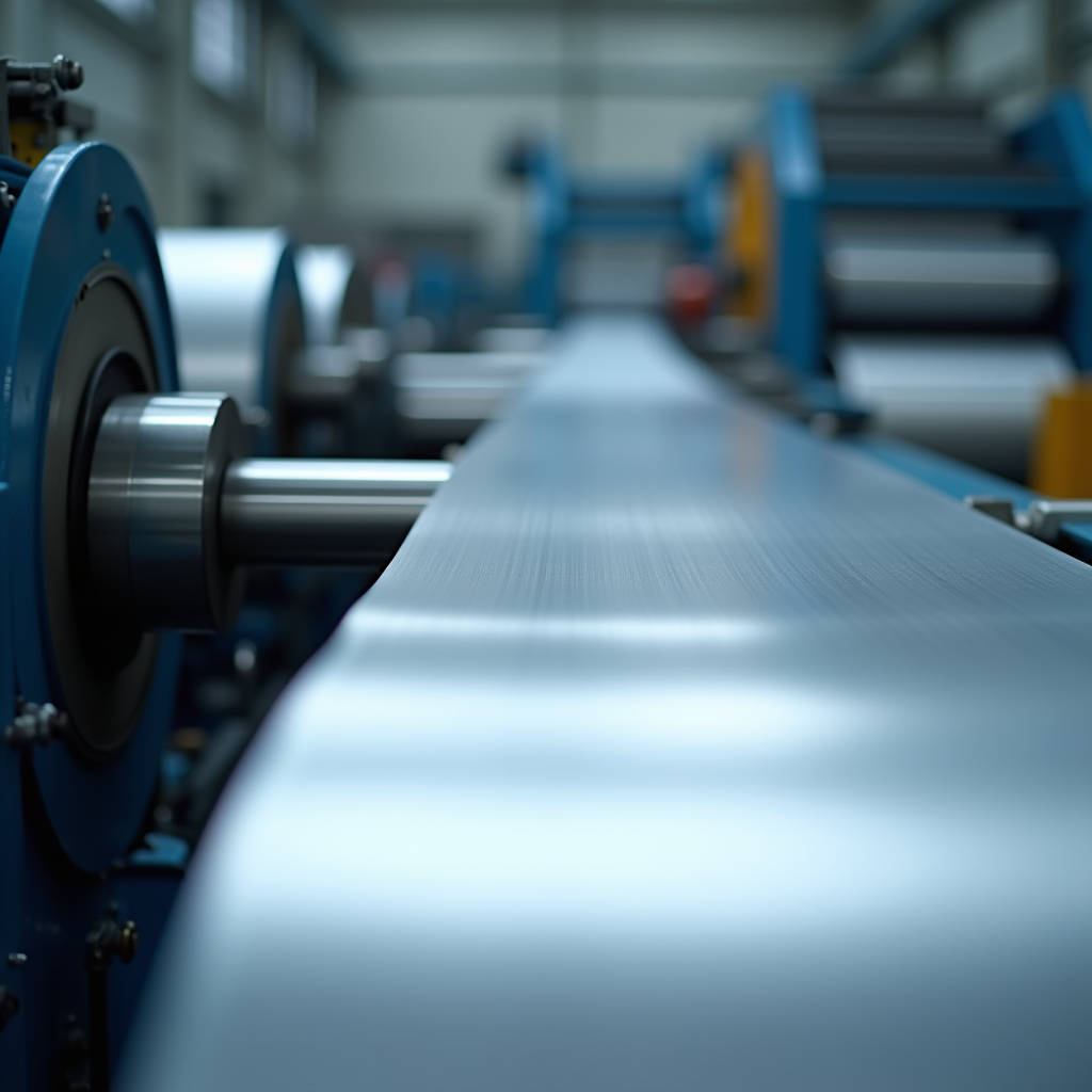
When a facade contractor places an order for 2.5mm solid aluminium cladding panels, the conversation rarely starts with the slitting line. It should. The width consistency, edge condition, and residual stress profile of the slit coil directly determine whether those panels arrive flat enough to install without rework. Aluminum Coil Slitting sits at the intersection of metallurgy, precision tooling, and downstream fabrication economics. A coil slit 0.15mm over tolerance on a 1,219mm wide master coil does not just waste material. It forces the fabricator to recalibrate every downstream station: levelling, shearing, bending, and routing. For procurement managers and facade engineers, understanding what happens at the slitter means understanding why some panel batches lay dead flat on the curtain wall while others ripple under glancing light.
The Engineering Reality Behind Slit Width Tolerance
Aluminum Coil Slitting looks deceptively simple. A master coil unwinds, passes through a set of rotary knives, and emerges as multiple narrower coils. The physics underneath that description is brutal. A 2.5mm thick 3003-H14 or 5052-H32 aluminium coil moving at 150 to 200 meters per minute carries enormous kinetic energy. The slitter knives must overcome the shear strength of the material while maintaining a clearance gap measured in microns. For aluminium, the optimal knife clearance typically runs between 8% and 12% of material thickness. On a 2.5mm coil, that means a gap of 0.20mm to 0.30mm. Too tight and the knives wear prematurely, generating burr. Too loose and the material tears rather than shears, producing a ragged edge that causes coil collapse during recoiling.
The tolerance standard most fabricators reference is ASTM B209 for aluminium sheet and plate, but slitting tolerances specifically fall under the jurisdiction of the processor's internal capability. A precision slitter running properly maintained tooling can hold ±0.125mm on width for material up to 3.0mm thickness. Commodity-level slitting often drifts to ±0.25mm or worse. That 0.125mm difference, multiplied across 20 panels on a facade module, creates a cumulative 2.5mm gap that the installer must absorb with shims or sealant. The math is unforgiving, and the cost lands on the installation crew.
How Slitting Edge Quality Drives Fabrication Outcomes
The edge left by the slitting knives is not a cosmetic detail. It is a structural feature that propagates through every subsequent process. A clean shear edge exhibits minimal burr height, typically under 0.025mm for quality aluminium slitting. Burr exceeding 0.05mm creates three problems downstream. First, it scores the surface of adjacent coil wraps during recoiling, leaving linear scratches that telegraph through PVDF coatings. Second, it interferes with panel interlock geometry on rainscreen systems where panel edges must seat cleanly against gaskets. Third, and most critically for solid aluminium cladding panels, burr acts as a stress concentrator during bending operations. When a panel edge with a 0.08mm burr goes through a press brake, the burr root becomes the initiation point for micro-cracking along the bend line.
Burr direction matters too. Slitting knives can be configured to push the burr toward the top or bottom face of the coil. For cladding panels that will receive a visible PVDF or FEVE coating on the weather face, the burr should be oriented away from that face. This prevents the burr shadow from telegraphing through the coating and creating a faint but visible line along panel edges under raking sunlight. Fabricators who specify slit coil from processors like Futeng® typically request burr-down orientation for coated stock, a detail that costs nothing to implement but saves significant rework on the finishing line.
Residual Stress and the Flatness Problem
Master aluminium coils carry residual stress from the hot rolling and cold rolling processes. The slitting operation does not simply cut the coil; it redistributes that stress. As the knives separate the material, the outer strips relax differently than the center strips. A strip taken from the edge of the master coil has one free edge and one sheared edge, creating an asymmetric stress profile that manifests as camber, edge wave, or center buckle. This is why slit coil for architectural cladding requires tighter camber specifications than coil destined for less demanding applications.
The industry benchmark for camber in slit aluminium coil is 3mm per 2,000mm of length for precision work. Commodity slitting may allow 6mm or more. For a 4,000mm long cladding panel, 6mm of camber translates to a panel that will not align with its neighbors on the facade grid. The installer can force it, but the resulting stress concentrates at the anchor points, and thermal cycling will eventually relax the panel into a visible wave. The fix is not a stronger installer. The fix is upstream, at the slitter, where proper tension control and strip separation during recoiling preserve the flatness engineered into the master coil.
Slitter Tooling and Material-Specific Considerations
Aluminium is not steel. The same slitting line that handles 3mm cold-rolled steel without issue can destroy 3mm aluminium if the operator applies steel-grade parameters. Aluminium's lower modulus of elasticity means it deflects more under the same tension. Its higher coefficient of thermal expansion means heat generated at the shear zone dissipates differently. And its softer surface is far more susceptible to pick-up on the slitter knives, where aluminium oxide accumulates on the cutting edges and degrades cut quality progressively through a production run.
Tool steel selection for aluminium slitting leans toward grades with high wear resistance and low adhesion characteristics. D2 tool steel with appropriate heat treatment to 58-60 HRC is common, though some processors use carbide knives for extended runs on abrasive 5000-series alloys. The knife geometry also differs from steel slitting. Aluminium requires a sharper rake angle, typically 1.5 to 2.5 degrees, to initiate a clean shear fracture rather than a ductile tear. The stripper rings that separate the slit strips must be set with minimal contact pressure to avoid marking the aluminium surface. Even a minor rub mark on the coil face will show through a 30-micron PVDF coating as a dull streak.
Coating Compatibility and Slit Coil Storage
Most solid aluminium cladding panels receive their architectural coating after slitting and fabrication, but a significant portion of the market uses pre-painted coil. When slit coil carries a PVDF or FEVE coating, the slitting process introduces risks that bare coil does not face. The coating at the cut edge experiences micro-delamination if knife clearance is not optimized. The recoiling tension must be reduced to prevent coating cracking at the strip edges. And the slit coils must be interleaved with protective paper or film to prevent the burr from scratching the coating on adjacent wraps.
Storage conditions after slitting are equally critical. Aluminium slit coil stored in an unheated warehouse in a humid climate develops condensation between the tightly wound wraps. That moisture, trapped against the aluminium surface, initiates white rust on 5000-series alloys and general oxidation on 3000-series material. For architectural applications where the panel surface must be pristine, slit coil should be stored indoors at controlled humidity below 60% RH and used within 30 days of slitting. Longer storage invites the kind of surface degradation that requires additional pretreatment before coating, adding cost and risking adhesion failure.
| Parameter | Precision Slitting | Commodity Slitting | Impact on Cladding Panels |
|---|---|---|---|
| Width Tolerance | ±0.125mm | ±0.25mm to ±0.50mm | Cumulative gap errors across facade modules |
| Burr Height | <0.025mm | 0.05mm to 0.10mm | Coating telegraphing, edge cracking in bending |
| Camber (per 2,000mm) | <3mm | 5mm to 8mm | Panel misalignment, thermal stress buckling |
| Knife Clearance Control | 8-12% of gauge | Variable, often >15% | Ragged edge, coil collapse, coating damage |
| Surface Protection | Protective film or paper interleave | Often none | Scratches, oxidation, pretreatment cost |
| Alloy-Specific Setup | Yes, per alloy group | Generic steel parameters | Surface marking, poor edge quality on 5xxx |
The Slitting Line Configuration That Matters for Facade Work
A slitting line is a system, not a machine. The uncoiler, the slitter head, the tension device, and the recoiler must work in concert, and any weakness in one component degrades the output regardless of how precise the knives are. For aluminium coil destined for solid cladding panels, the line configuration should include several features that are not universal on general-purpose slitting equipment.
Loop control between the uncoiler and slitter head is essential. Without a controlled loop, tension fluctuations from the uncoiler brake transmit directly into the slitting zone, causing width variation as the material stretches and relaxes. A deep loop pit with photoelectric sensors provides the buffer that decouples uncoiling dynamics from slitting accuracy. Tension control at the recoiler is equally critical. The recoiler must apply consistent, controlled tension to each slit strip independently. If one strip winds tighter than its neighbor, the looser strip will telescope during recoiling, creating a coil that is unusable for automated fabrication lines. Separator tooling that maintains physical gaps between the slit strips as they enter the recoiler prevents the edges from interlocking and tearing.
For architectural aluminium, the slitter head should be equipped with quick-change knife arbors. This allows the processor to swap tooling between alloy groups without excessive downtime. A slitter running 3003 coil all week can accumulate aluminium oxide on the knives that will mark 5052 material on the next run. Dedicated tooling sets for different alloy families, or at minimum a thorough cleaning protocol between alloy changes, prevents cross-contamination of surface quality.
Specifying Slit Coil for Solid Aluminium Cladding
Procurement specifications for slit coil used in architectural cladding should go beyond alloy and temper. The spec should address the dimensional and surface parameters that directly affect panel fabrication yield and installed appearance. Width tolerance of ±0.15mm maximum is achievable from quality processors and should be the default requirement for panel widths that will be exposed on the facade. For panels with interlocking joints, that tolerance should tighten to ±0.10mm.
Camber should be specified at 3mm maximum per 2,000mm of length, measured on a flat inspection table with the coil in its free state. Edge burr should not exceed 0.03mm on either face, and the burr direction should be specified relative to the coated face. Surface condition requirements should reference the absence of roll marks, pick-up, scratches deeper than 0.02mm, and oil staining. The coil should be supplied with interleaving paper or protective film if it will not be fabricated within 14 days of slitting.
These specifications are not aspirational. They are routinely met by processors who invest in modern slitting equipment and maintain disciplined tooling management. The cost difference between precision-slit coil and commodity-slit coil for a typical facade project runs between 3% and 7% of the raw material cost. That premium buys a reduction in fabrication scrap, lower rework rates on the coating line, and fewer field adjustments during installation. On a project with 5,000 square meters of solid aluminium cladding, the precision slitting premium typically pays for itself through reduced installation labor alone.
Alloy Selection and Slitting Behavior
The two aluminium alloy families most common in solid cladding panels, 3000-series and 5000-series, behave differently on the slitting line. 3003-H14, the workhorse for architectural sheet, slits cleanly with standard tooling and moderate tension. Its relatively low magnesium content means less work hardening during the shear process and less tendency to gall on the knife edges. 5052-H32, specified for coastal and high-corrosion environments, contains 2.2% to 2.8% magnesium. That magnesium content increases the material's tendency to adhere to tool steel under the heat and pressure of the shear zone. Slitters running 5052 typically reduce line speed by 15% to 20% compared to 3003 and may use carbide knives or specialized coatings on the knife edges to combat galling.
The temper condition also matters. H14 temper (strain-hardened, half-hard) provides a good balance of formability and strength for cladding panels. H32 temper (strain-hardened and stabilized) offers similar mechanical properties but with improved resistance to room-temperature aging. From a slitting perspective, the stabilized temper in H32 can produce slightly cleaner edges because the material has less residual cold-work energy to release during the shear. The difference is subtle but measurable in burr height and edge cracking tendency during subsequent bending operations.
For projects specifying 2.0mm, 2.5mm, or 3.0mm solid aluminium panels, the slitting parameters must be dialed in per gauge. Thinner material requires tighter knife clearance to prevent tearing. Thicker material requires more robust tension control to prevent coil collapse. A processor who runs 2.0mm and 3.0mm on the same line without adjusting setup parameters is producing at least one of those gauges sub-optimally. The procurement team should verify that the slitter has documented setup procedures per alloy, temper, and gauge combination.
Quality Verification at Receiving
When slit coil arrives at the fabrication facility, a structured receiving inspection catches problems before they reach the production line. Width measurement should be taken at multiple points along the coil length using calibrated calipers or a go/no-go gauge. Camber is checked by laying a 2,000mm sample on a flat granite or steel inspection table and measuring the maximum deviation from a straightedge. Burr height is measured with a micrometer or optical comparator on a cross-sectioned sample. Surface condition is inspected under adequate lighting, ideally 1,000 lux minimum, with the inspector looking for linear scratches, roll marks, and staining.
The coil should also be checked for telescope, where individual wraps have shifted laterally relative to each other. Telescope exceeding 1.5mm indicates tension control problems during slitting and will cause feeding issues on automated fabrication lines. The coil ID should be clean and undamaged; a scored or out-of-round ID suggests the coil was mishandled during recoiling or transport. These receiving checks take 15 to 20 minutes per coil and prevent hours of production disruption.
Economic Logic of Precision Slitting for Facade Projects
The cost structure of a solid aluminium cladding project breaks down roughly into 40% material, 35% fabrication, and 25% installation. Precision slitting affects all three. Material yield improves because width-accurate coil reduces trim waste at the shear and routing stations. Fabrication efficiency improves because flat, camber-free coil feeds through automated lines without jamming or misalignment. Installation cost drops because panels that match their specified dimensions fit the facade grid without field modification.
Consider a mid-rise commercial building with 3,000 square meters of 2.5mm solid aluminium rainscreen panels. Commodity-slit coil with ±0.25mm width tolerance might produce 3% to 5% fabrication scrap from panels that fall outside dimensional tolerance. That scrap represents not just the raw aluminium cost, but also the embedded fabrication labor, coating cost, and handling. At $80 to $120 per square meter installed for a quality rainscreen system, a 3% scrap rate on 3,000 square meters represents $7,200 to $10,800 in avoidable cost. The precision slitting premium on the raw coil for that project is typically $2,500 to $4,000. The arithmetic favors precision.
Processors supplying architectural-grade slit coil understand this calculus. They maintain their slitting lines to the standards required for facade work, document their quality control procedures, and provide mill test reports that trace the coil back to the original cast and rolling campaign. For procurement managers specifying solid aluminium cladding panels, the slitting source is not a commodity decision. It is a quality gate that determines whether the panels on the truck will install smoothly or fight the crew every step of the way.
The slitting line does not get the attention that coating systems or panel joint designs receive in architectural specifications. That is a gap worth closing. The next time a facade specification crosses your desk, look past the PVDF resin type and the panel thickness. Ask where the coil was slit, to what tolerances, and with what quality verification. The answers will tell you more about the likely field performance of the cladding than any datasheet.