How Aluminum Extrusion Die Design Controls Solid Aluminium Cladding Panel Flatness and Stiffener Integrity
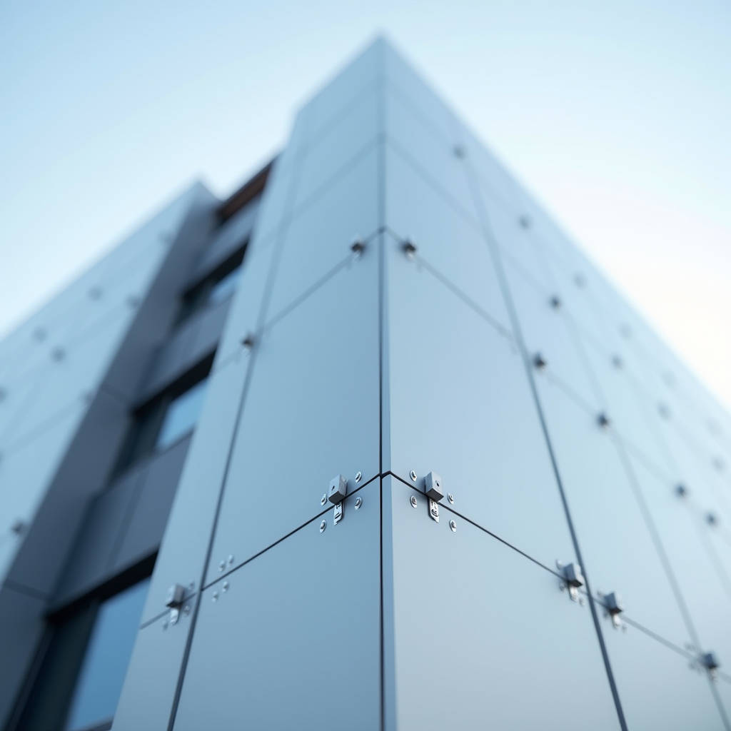
When a facade contractor orders 3.0mm solid aluminium cladding panels for a 40-story tower, the conversation rarely starts with the extrusion die. It should. The die is where panel flatness is won or lost, where coating adhesion begins, and where the difference between a 12-week lead time and a 26-week delay gets decided. Aluminum Extrusion Die Design shapes the internal stiffening ribs, edge returns, and interlocking geometries that define how a solid aluminium panel performs under wind load, thermal cycling, and decades of UV exposure. A poorly conceived die produces panels that arrive with residual stress locked into the metal. A well-engineered one delivers profiles that weld cleanly, accept PVDF coatings uniformly, and hold their camber within 0.2% of length. This article examines the die design decisions that directly affect cladding panel quality, cost, and long-term durability on commercial building envelopes.
Why the Die Matters More Than the Panel Thickness
Procurement teams often fixate on aluminium grade and sheet thickness. A 2.5mm 3003-H14 panel versus a 3.0mm 5052-H32 panel is a real debate. But the extrusion die that forms the panel's internal geometry exerts equal influence on structural performance. The die determines whether the stiffening ribs are perfectly perpendicular to the face, whether the corner radii are consistent, and whether the metal flow during extrusion introduces micro-tearing at thin sections.
Solid aluminium cladding panels for high-rise facades typically incorporate extruded sub-frames, mounting rails, or integrated stiffeners. These are not off-the-shelf shapes. They are custom profiles born from a steel die that must balance three competing demands: metal flow uniformity, dimensional tolerance, and die longevity. When the die's bearing length is miscalculated by even 0.5mm, the extruded profile emerges with a slight twist. That twist translates into a panel that will never sit flush against the substructure, regardless of how many shims the installer uses.
The Aluminum Extrusion Die Design process for cladding components begins with the profile's tongue ratio. For a typical stiffener rib that measures 3mm wide and protrudes 25mm from the panel back, the tongue ratio is approximately 8.3:1. Most die makers consider anything above 8:1 a high-risk geometry. The solution involves adjusting bearing lengths, adding feeder plates, or redesigning the profile to reduce the projection. Each of these decisions adds cost but prevents the die from failing after 8,000 linear meters instead of lasting 80,000.
Die Types and Their Relevance to Cladding Profiles
Three die categories dominate aluminium extrusion: solid dies, hollow dies, and semi-hollow dies. For solid aluminium cladding panel components, the choice is rarely arbitrary. Each type imposes distinct constraints on profile geometry, production speed, and die cost.
Solid Dies: The Workhorse for Panel Stiffeners
Solid dies produce profiles without internal voids. A typical T-shaped stiffener rib or an L-bracket for panel edge returns uses a solid die. The die consists of a single steel disk with a machined opening matching the profile cross-section. Manufacturing cost ranges from $800 to $2,500 depending on diameter and complexity. Lead time is typically 10 to 14 days.
The limitation is straightforward: solid dies cannot produce hollow sections. When a panel design calls for a stiffener with a closed rectangular channel to reduce weight while maintaining bending stiffness, a solid die is not an option. The designer must either switch to a hollow die or accept a solid rib with higher material consumption.
Hollow Dies: When Weight Reduction Drives Design
Hollow dies use a two-piece construction with a mandrel suspended inside the die opening by bridge supports. The aluminium billet flows around the mandrel and welds back together in the welding chamber before exiting the die. This is how rectangular tubes, channels with internal ribs, and complex multi-void profiles are made.
For cladding applications, hollow dies become relevant when the panel system uses extruded mullion sections or when the stiffener grid incorporates a tubular cross-section for torsional rigidity. The die cost is higher—typically $2,000 to $6,000—and the extrusion speed is 20% to 40% slower than an equivalent solid profile. The weld lines where the metal rejoins require careful die design to avoid weak zones that could crack under cyclic wind loading.
A practical consideration: hollow dies demand more frequent maintenance. The mandrel experiences higher thermal stress, and the bridge supports are prone to wear. A well-maintained hollow die for 6063-T5 alloy can produce 50,000 to 70,000 linear meters before requiring reconditioning. A solid die for the same alloy often exceeds 100,000 meters.
Semi-Hollow Dies: The Middle Ground
Semi-hollow dies handle profiles where the enclosed area is partially bounded—think of a C-channel with a narrow opening. The die behaves similarly to a solid die but includes a tongue section that extends into the profile opening. Tongue ratio becomes the critical design parameter. A ratio above 3:1 typically requires a semi-hollow die classification, and the die maker must reinforce the tongue to prevent deflection during extrusion.
For cladding panel edge profiles that incorporate a snap-fit groove or a gasket channel, semi-hollow dies are common. The die cost falls between solid and hollow dies, and the production speed is comparable to solid dies if the tongue ratio stays below 6:1.
Material Selection for Dies: H13 Steel and Its Alternatives
The die material directly affects how many kilometers of cladding profile can be extruded before dimensional drift exceeds tolerance. H13 hot-work tool steel remains the industry standard, hardened to 46-50 HRC. It offers adequate thermal fatigue resistance at extrusion temperatures of 450°C to 500°C and costs roughly $12 to $18 per kilogram in finished die form.
For high-volume cladding projects—think 50,000 square meters of panels requiring 120,000 linear meters of stiffener extrusion—upgrading to H11 or H13 modified with higher molybdenum content can extend die life by 30% to 50%. The incremental cost is approximately 25% on the die price, but the avoided downtime from die changes and the improved profile consistency often justify the investment.
Nitriding the die surface adds a wear-resistant layer 0.1mm to 0.2mm deep. Nitrided dies for 6063-T6 profiles typically last 40% longer than uncoated dies. For 6061-T6, which is harder and more abrasive, nitriding is practically mandatory. The cladding industry predominantly uses 3003 and 5052 alloys for the panel faces, but the extruded stiffeners and sub-frames are almost always 6063-T5 or 6063-T6. The die material must match the alloy's abrasiveness.
Futeng® has observed in its production data that dies nitrided to a case depth of 0.15mm consistently deliver profile tolerances within ±0.15mm for the first 60,000 linear meters when extruding 6063-T5 stiffeners. Beyond that threshold, the bearing surface begins to erode and dimensional scatter increases.
Bearing Length and Metal Flow: The Physics of Straight Panels
A flat cladding panel demands a flat extruded stiffener. The stiffener's flatness originates in the die's bearing geometry. The bearing is the land area inside the die opening where the aluminium makes final contact before exiting. Bearing length controls local metal velocity. Longer bearing equals more friction equals slower metal flow. Shorter bearing equals faster flow.
In a typical T-section stiffener, the central web is thicker than the flange edges. Without bearing compensation, the thicker section would flow faster, causing the profile to curve toward the slower-flowing thin sections as it exits the die. The die designer counters this by shortening the bearing on the thick section and lengthening it on the thin sections. The calculation is iterative and relies heavily on experience with specific alloys.
A 6063-T5 profile with a 4mm web and 2mm flange tips might require a bearing length of 6mm on the web and 12mm on the flange tips to achieve balanced flow. Get the balance wrong by 1mm, and the profile emerges with a bow of 3mm to 5mm per meter. That bow, when welded to the back of a 3.0mm aluminium panel, pulls the panel face out of flatness. The problem compounds when panels are installed adjacent to each other on a facade, creating visible waves across the building envelope.
The Aluminum Extrusion Die Design workflow must account for the fact that cladding stiffeners are long, slender profiles. A stiffener measuring 3,000mm long with a cross-section of 25mm by 30mm has a slenderness ratio that makes it highly sensitive to bearing-induced curvature. Post-extrusion straightening can correct minor bow, but it adds a processing step and introduces residual stress that may relax over time, causing the panel to warp months after installation.
Thermal Considerations in Die Design for Cladding Applications
Aluminium cladding panels on a sun-exposed facade in Dubai or Singapore experience surface temperatures from -10°C to 85°C across a 24-hour cycle. The extruded stiffeners bonded to the panel back expand and contract at the same rate as the panel face—approximately 2.4mm per meter across a 100°C temperature swing. This is manageable when the stiffener and panel are the same alloy. When they differ, differential thermal expansion creates shear stress at the weld points.
The die design influences this indirectly. A stiffener extruded with uniform wall thickness heats and cools evenly. A stiffener with abrupt thickness transitions develops hot spots during extrusion and thermal stress concentrations in service. The die designer must ensure that wall thickness variations are gradual, with transition radii of at least 1.5 times the thickness difference.
For projects in coastal environments, the die design also affects the profile's ability to drain condensation. Stiffeners with weep holes or drainage channels require the die to incorporate small projections that form these features. The die maker must ensure these projections are robust enough to survive the extrusion pressure without breaking off. A broken die projection that falls into the extrusion stream can score the profile surface, creating a corrosion initiation site.
Cost Structure of Extrusion Dies for Cladding Projects
Project budgets often treat die cost as a fixed line item. It is more useful to think of it as an amortized cost per linear meter of extrusion. The table below breaks down the economics across die types for a typical cladding project requiring 80,000 linear meters of stiffener profile.
| Die Type | Initial Die Cost (USD) | Die Life (Linear Meters) | Die Cost per 1,000m | Typical Extrusion Speed (m/min) | Profile Complexity |
|---|---|---|---|---|---|
| Solid Die (H13, uncoated) | $1,200 - $2,500 | 80,000 - 120,000 | $10 - $31 | 25 - 40 | Low-Medium |
| Solid Die (H13, nitrided) | $1,800 - $3,200 | 110,000 - 160,000 | $11 - $29 | 25 - 40 | Low-Medium |
| Semi-Hollow Die | $2,000 - $4,500 | 60,000 - 90,000 | $22 - $75 | 20 - 35 | Medium |
| Hollow Die (2-piece) | $2,500 - $6,000 | 50,000 - 70,000 | $36 - $120 | 15 - 25 | High |
| Hollow Die (4-piece, complex) | $5,000 - $12,000 | 40,000 - 60,000 | $83 - $300 | 10 - 18 | Very High |
The numbers reveal a counterintuitive reality: for high-volume cladding projects, the cheapest die is often the most expensive choice. A $1,200 solid die that fails at 40,000 meters—half its rated life—due to poor bearing design or inadequate nitriding doubles the amortized cost and adds a 14-day lead time penalty for a replacement die. The project absorbs not just the new die cost but also the extrusion line downtime and potential panel delivery delays.
Profile Geometry Rules That Prevent Die Failure
Die designers work within a set of geometric constraints that, when violated, dramatically increase the probability of die failure. Cladding panel designers who understand these rules can avoid costly redesign cycles.
Minimum wall thickness: For 6063 alloy extruded stiffeners, the practical minimum is 1.0mm for small profiles and 1.5mm for profiles with a circumscribing circle diameter above 100mm. Thinner walls cause the die bearing to overheat and erode rapidly. For 6061 alloy, add 0.3mm to these minimums.
Corner radii: Sharp internal corners concentrate stress in the die steel. A minimum inside radius of 0.5mm is standard, and 0.75mm is recommended for profiles that will be anodized after extrusion. The die's corner experiences the highest thermal load, and a radius below 0.3mm virtually guarantees premature cracking.
Tongue ratio: As noted earlier, a tongue ratio above 8:1 for solid dies and above 3:1 for semi-hollow dies triggers additional engineering review. The die maker must assess whether the tongue can be supported adequately or whether the profile must be redesigned.
Symmetry: Asymmetric profiles tend to twist during extrusion because metal flows unevenly around the die opening. A stiffener with a 3mm flange on one side and a 6mm flange on the opposite side will almost certainly twist unless the die incorporates a twist correction in the bearing design. Symmetrical profiles are cheaper to die and extrude faster.
Circumscribing circle diameter: The CCD is the smallest circle that contains the entire profile cross-section. Standard extrusion presses for cladding profiles operate with 7-inch to 10-inch diameter containers. The profile CCD must be at least 0.5 inches smaller than the container diameter to allow for the dummy block and thermal expansion. A profile with a 9.5-inch CCD on a 10-inch press leaves no margin for error.
Die Correction and Trial Runs: The Iteration That Cannot Be Skipped
No die produces a perfect profile on the first extrusion. The initial trial run reveals deviations between the designed profile and the actual extruded shape. The die then undergoes correction—a manual process where a skilled die corrector adjusts bearing lengths, modifies feeder geometry, or polishes specific areas to bring the profile within tolerance.
For cladding stiffener profiles, the typical correction cycle involves one to three iterations. Each iteration consumes 2 to 4 hours of die corrector time and 50 to 100 kilograms of billet material. The total cost of die correction ranges from $300 to $1,200 per die, depending on complexity. This cost should be factored into the project budget from the outset.
The corrected die is then sample-extruded at production speed to verify dimensional stability over a full billet length. A profile that measures within tolerance at the start of the billet but drifts out of tolerance by the end indicates a thermal balance problem in the die. The die heats up during extrusion, and the bearing geometry shifts as the steel expands. A properly designed die maintains dimensional stability across the full thermal cycle.
According to guidelines published by the Aluminum Extruders Council, the standard dimensional tolerance for extruded profiles used in architectural applications is ±0.15mm for dimensions up to 25mm, and ±0.25mm for dimensions between 25mm and 75mm. Cladding panel stiffeners typically fall within these ranges, and the die must be corrected to deliver profiles that stay within these limits across the entire production run.
Alloy Selection and Its Impact on Die Wear
The aluminium alloy extruded through the die determines the die's wear rate. 6063-T5 is the most common alloy for architectural extrusions because it flows easily, welds well in hollow dies, and offers good corrosion resistance. Its relatively low hardness—approximately 60 HB on the Brinell scale—means it is gentle on die bearings.
6061-T6, by contrast, has a hardness of approximately 95 HB and contains higher levels of magnesium and silicon. It is significantly more abrasive. A die that produces 100,000 meters of 6063-T5 profile may produce only 50,000 to 60,000 meters of 6061-T6 before the bearing surfaces show measurable wear. For cladding projects that specify 6061-T6 stiffeners for higher strength, the die cost per linear meter effectively doubles.
3003 and 5052 alloys, which are commonly used for the solid aluminium panel faces themselves, are rarely extruded into complex profiles. They are typically supplied as flat sheets and brake-formed or welded. The extrusion dies for cladding applications therefore focus almost exclusively on 6xxx series alloys for the stiffener and sub-frame components.
The ASTM B221 standard governs the dimensional tolerances for extruded aluminium profiles, and the AAMA 611 standard specifies the performance requirements for anodized architectural aluminium. Die designers must be familiar with both standards to ensure the extruded profiles meet the end-use requirements for cladding systems.
Production Volume and Die Strategy
A project requiring 5,000 linear meters of stiffener extrusion has a fundamentally different die strategy from one requiring 200,000 linear meters. For the small project, a single solid die manufactured from standard H13 steel without nitriding is entirely adequate. The die will produce the required volume with plenty of life remaining.
For the large project, the die strategy shifts toward redundancy and durability. Two identical dies are ordered simultaneously. Die A runs the first 80,000 meters, then Die B takes over while Die A is reconditioned. The reconditioning process involves grinding the die face to remove surface cracks, re-nitriding, and re-polishing the bearing surfaces. A well-maintained die can be reconditioned three to five times before the bearing geometry degrades beyond correction.
The cost of a spare die—typically $2,000 to $5,000—is cheap insurance against the cost of a halted extrusion line. An idle extrusion press costs the factory between $500 and $1,500 per hour in lost revenue. A 24-hour stoppage while waiting for a replacement die can erase the profit margin on the entire project.
Futeng® and other experienced suppliers serving the international cladding market typically maintain relationships with multiple die makers to ensure that replacement dies can be manufactured within 7 to 10 days if the primary die maker is at capacity. This supply chain redundancy is particularly important for projects in the Middle East and Southeast Asia, where construction schedules are aggressive and liquidated damages for delays are substantial.
Quality Control at the Die-to-Panel Interface
The transition from extruded stiffener to finished cladding panel involves welding, assembly, and surface finishing. Each step can reveal die-related defects that were invisible in the raw extrusion.
Weldability: Stiffeners with inconsistent wall thickness create uneven heat distribution during welding, leading to distortion. The die must produce wall thickness variations within ±0.1mm of the nominal value to ensure consistent weld quality.
Coating adhesion: The extruded surface finish affects how well PVDF or powder coating adheres to the stiffener. A die with worn bearings produces a rough, torn surface with microscopic fissures. These fissures trap air and contaminants, creating coating defects that may not appear until months after installation. The die bearing surface should be polished to a roughness of 0.4μm Ra or better for architectural-grade extrusions.
Dimensional stack-up: A cladding panel system typically involves multiple extruded components—stiffeners, edge profiles, mounting clips, and gasket channels. The dimensional tolerances of each component stack up. If each component is at the extreme of its tolerance range, the assembled panel may not fit the substructure. The Aluminum Extrusion Die Design must account for this stack-up by targeting the nominal dimension rather than allowing the tolerance band to drift toward one extreme.
The ISO 2768 standard for general tolerances provides a reference framework, but cladding projects typically require tighter control. A practical approach is to specify that extruded components for cladding systems must meet half the standard tolerance band—±0.08mm instead of ±0.15mm for dimensions under 25mm. This tighter specification increases die cost by approximately 15% to 25% but eliminates field-fit problems during installation.
Lead Time Realities and How Die Design Affects Them
The standard lead time for a custom extrusion die is 10 to 18 working days, depending on complexity and the die maker's workload. But the die is only the first step. After die manufacturing comes die trial, correction, sample approval, and only then production extrusion. The full timeline from die order to production-ready extrusion is typically 4 to 6 weeks.
Rushed die manufacturing invites problems. A die made in 7 days instead of 14 days may skip the stress-relief heat treatment step, leaving residual stresses in the steel that cause the die to crack during its first production run. The 7-day saving becomes a 21-day delay when the die fails and must be remade.
For cladding projects with tight construction schedules, the die design phase should begin as soon as the panel system design is finalized. The die design itself takes 2 to 3 days of engineering time, and the design review with the die maker adds another 1 to 2 days. This 5-day investment at the front end can prevent weeks of delay during the production phase.
The Aluminum Extrusion Die Design process, when executed methodically, transforms a custom cladding panel system from a concept into a repeatable, quality-controlled product. The die is a small steel disk that costs a few thousand dollars, but it controls the geometry, surface quality, and production economics of every linear meter of extrusion that goes into the building envelope. Treating it as a commodity purchase rather than an engineering investment is a mistake that manifests in panel flatness deviations, coating failures, and installation delays. For the facade contractor and the project owner, the die is not a line item to minimize. It is the foundation on which the entire cladding system's performance is built.