Aluminum Extrusion Machining Tolerances and CNC Operations for Curtain Wall Facade Systems
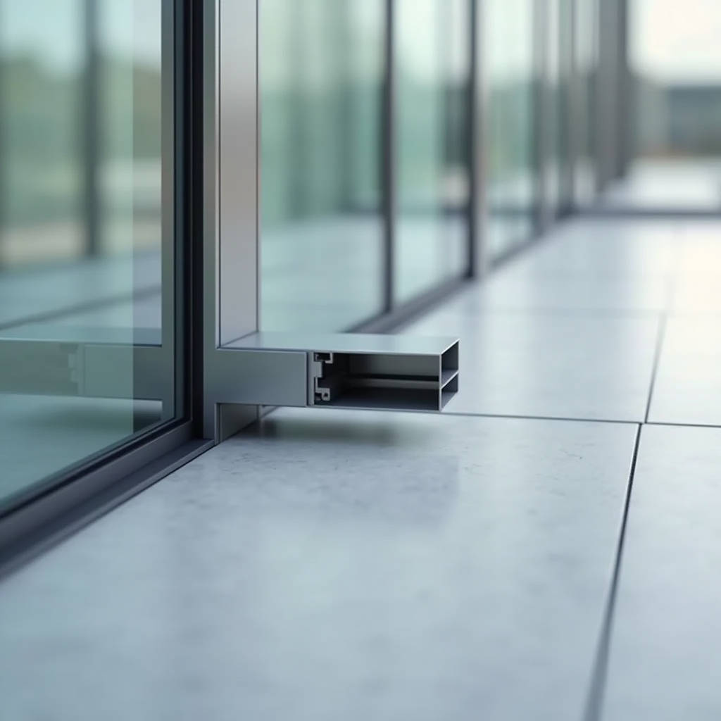
The curtain wall industry runs on tight tolerances. When a 3.0mm solid aluminium panel arrives on site with bolt slots misaligned by even half a millimeter, the ripple effect hits installation schedules, waterproofing integrity, and ultimately the project's completion date. Aluminum Extrusion Machining sits at the center of this precision equation. It is not the extrusion process itself, but the secondary CNC operations that transform a raw extruded profile into a dimensionally exact, ready-to-install facade component. For procurement managers and facade engineers, understanding what happens after the billet leaves the die determines whether your cladding system performs as specified or becomes a costly field modification exercise.
Where Extrusion Ends and Machining Begins
Raw aluminium extrusion produces a continuous profile with a consistent cross-section. That profile, however, is rarely ready for the building envelope. The extrusion process itself has inherent dimensional variation. According to AAMA standards, extruded aluminium profiles carry tolerances that can range from ±0.2mm to ±0.5mm depending on profile size and wall thickness. For curtain wall applications where panels must interlock with gaskets, pressure plates, and structural mullions, these as-extruded tolerances are insufficient.
Aluminum Extrusion Machining bridges this gap. It encompasses precision cutting to length, drilling bolt patterns, milling drainage slots, tapping threads for structural fasteners, and routing access openings for hardware. Each operation removes material from the extruded profile to achieve geometry that the extrusion die alone cannot deliver. The distinction matters because it defines who is responsible for dimensional accuracy: the extruder provides the raw shape, the machining center creates the finished component.
CNC Operations That Define Facade Quality
Modern aluminium extrusion machining centers are purpose-built for long, slender workpieces. Unlike general-purpose vertical machining centers, these machines feature horizontal spindles, extended work envelopes, and automated material handling systems that can process profiles up to 7 meters in length. The operations break down into several categories, each with direct consequences for cladding performance.
Precision Cut-to-Length
The most fundamental machining operation is cutting extruded profiles to exact length. A ±0.3mm tolerance on a 3-meter panel may seem acceptable, but cumulative error across 50 panels on a single elevation creates visible alignment problems. High-end machining centers use servo-driven saw blades with automatic length measurement systems that compensate for thermal expansion of the aluminium. In a 40°C temperature swing between morning fabrication and afternoon installation, a 3-meter 6063-T6 profile expands by approximately 2.5mm. Machining operations that account for this thermal coefficient prevent field trimming.
Drilling and Tapping for Structural Connections
Solid aluminium cladding panels typically mount to a subframe using stainless steel bolts threaded into machined holes. The drilling operation must position holes relative to the panel's reference edges with positional accuracy within ±0.1mm. Tapping operations cut internal threads into the aluminium for M6, M8, or M10 fasteners. The thread engagement depth in a 3.0mm panel is limited, so machinists often specify helical coil inserts for high-load connections. This is a detail that separates suppliers who understand structural requirements from those who simply drill and ship.
Drainage and Ventilation Slotting
Rainscreen cladding systems require pressure equalization. Machined slots at the panel bottom edge allow water to drain and air to circulate behind the panel face. These slots, typically 6mm x 30mm, must be positioned consistently and deburred cleanly. A poorly machined slot with a sharp burr will tear EPDM gaskets during installation, compromising the weather seal. The slot geometry also affects the panel's effective wind load area, a factor that structural engineers must account for when specifying panel thickness.
Routing for Hardware and Accessories
Many solid aluminium panel systems incorporate concealed fixings, secret clips, or interlocking joinery. These require routed pockets on the panel's rear face, machined to precise depth without penetrating the visible front surface. For a 2.5mm-thick panel, the routing depth tolerance is typically held to ±0.05mm. Breaking through the face means scrapping the panel. This is where CNC program quality and tool condition directly impact material waste rates and per-square-meter costs.
Alloy Selection and Machinability
Not all aluminium alloys machine the same way. The choice of extrusion alloy affects tool life, surface finish, and the achievable tolerance. The table below summarizes the key alloys used in architectural extrusion and their machining characteristics.
| Alloy | Temper | Typical Facade Application | Machinability Rating | Tool Wear Factor | Surface Finish Quality |
|---|---|---|---|---|---|
| 6063 | T5/T6 | Curtain wall mullions, transoms, decorative trim | Good | Low | Excellent (anodizing grade) |
| 6061 | T6 | Structural brackets, high-load connectors | Good | Moderate | Good (machining marks visible) |
| 6005A | T6 | Load-bearing facade substructures | Fair | Moderate-High | Good |
| 6082 | T6 | Heavy structural components, base shoes | Fair | High | Moderate (requires post-machining finishing) |
| 6463 | T5 | High-gloss decorative trims, visible moldings | Excellent | Very Low | Superior (bright-dip anodizing grade) |
6063-T6 dominates architectural extrusion machining because it offers the best balance of extrudability, machinability, and surface finish. The alloy's relatively soft nature means carbide tooling can run at higher spindle speeds without excessive wear. For projects specifying bright anodized finishes, 6463-T5 provides superior surface response after machining, though it costs approximately 12-18% more than 6063 billet.
6061-T6 machines well but produces longer, stringier chips that can wrap around tool holders and mar finished surfaces. This alloy requires chip breakers on cutting tools and higher coolant flow rates. For structural connections where machined threads must withstand high pull-out loads, 6061-T6's higher ultimate tensile strength (310 MPa vs. 6063-T6's 240 MPa) justifies the additional machining complexity.
Tolerances That Actually Matter on Site
Drawing tolerances and field tolerances are not the same thing. A specification sheet might call for ±0.1mm on all machined features, but the installer cares about three things: does the panel fit the subframe, do the bolt holes align, and do the panel joints read as straight lines across the elevation. The following tolerances represent what experienced facade contractors consider acceptable for solid aluminium cladding panels.
- Panel overall length/width: ±0.5mm for panels up to 1500mm, ±0.8mm for panels 1500-3000mm
- Bolt hole position (relative to datum edges): ±0.2mm
- Bolt hole diameter: +0.1mm / -0.0mm
- Routed pocket depth (rear face): ±0.05mm
- Slot width (drainage/ventilation): ±0.3mm
- Cut edge squareness: 0.3mm deviation across panel width
- Flatness after machining: 0.4% of panel diagonal length
These numbers come from field experience, not theoretical machine capability. A CNC machining center might be capable of ±0.02mm positioning accuracy, but the extruded profile itself has variation, the fixture introduces error, and thermal effects shift dimensions throughout the day. Suppliers who quote machine-level tolerances on finished panels are either measuring before the part leaves the fixture or simply not measuring at all. Futeng® maintains a quality protocol where finished components are inspected on a granite surface plate after the part has thermally stabilized, ensuring the measured dimension reflects what arrives on site.
Common Machining Defects and Their Root Causes
When machined aluminium extrusions fail inspection, the defects usually trace back to a handful of process failures. Understanding these helps procurement teams evaluate supplier capability beyond the sales presentation.
Chatter Marks on Milled Surfaces
Chatter appears as a wavy surface pattern on routed pockets and milled edges. It results from inadequate workholding, where the long, slender extrusion vibrates at its natural frequency during cutting. The fix requires either vibration-dampening fixtures, shorter tool overhang, or reduced spindle speed. For 3-meter-long curtain wall profiles, dedicated extrusion machining centers use pneumatic clamping systems spaced every 400-500mm along the workpiece to suppress vibration.
Burr Formation at Hole Exits
When a drill bit breaks through the back side of an extrusion wall, it pushes material outward rather than cutting it cleanly. The resulting burr interferes with fastener seating and can create a galvanic corrosion point if it contacts stainless steel hardware. Proper burr control requires sharp tooling, correct feed rates, and in critical applications, a secondary deburring operation using a chamfer tool or vibratory finishing.
Positional Drift in Long Production Runs
Over hundreds of identical panels, tool wear and thermal growth of the machine itself can cause hole positions to drift by 0.1-0.2mm. This is invisible on individual parts but becomes apparent when panels are installed adjacent to each other. Suppliers who machine large curtain wall packages should demonstrate in-process inspection procedures, ideally using automated probing cycles that verify critical dimensions at programmed intervals.
Thread Galling in Tapped Holes
Aluminium is prone to galling, where friction during thread cutting causes material to tear and adhere to the tap. The result is rough, oversized threads with reduced strength. The solution involves using forming taps rather than cutting taps for aluminium, applying proper lubrication, and controlling tap entry speed. A formed thread displaces material rather than cutting it, producing a stronger thread with a burnished surface finish.
Cost Drivers in Extrusion Machining
Machining cost is not simply machine time multiplied by hourly rate. The real cost drivers are less obvious and often overlooked during the quoting stage.
Setup time dominates small batches. Programming a CNC machining center, loading tools, setting work offsets, and running first-article inspection can take 2-4 hours regardless of whether the batch is 10 panels or 1,000. For small custom projects, setup cost per panel can exceed the actual machining cost. This is why many suppliers impose minimum order quantities or charge setup fees that are amortized over larger volumes.
Tooling cost varies dramatically by geometry. Standard drills and end mills are commodity items. Custom form tools for routing specific clip geometries or interlocking joints can cost $500-$2,000 per tool. If the panel design requires three custom tools, the tooling investment alone can be $3,000-$5,000 before the first panel is machined. Smart design minimizes the number of unique machined features.
Scrap rate is the hidden margin killer. A 3% scrap rate on a $150-per-square-meter solid aluminium panel package translates to $4.50 per square meter in lost material. When machining operations push tolerances or tooling is worn, scrap rates can spike to 8-10%. The difference between a supplier running at 2% scrap and one running at 8% is roughly $9 per square meter—enough to swing a competitive bid by 5-7%.
Material handling adds cost non-linearly. Long, flexible aluminium extrusions require careful handling between operations. Automated loading systems reduce labor but add capital cost. Manual handling risks bending and surface damage. The optimal approach depends on volume: for projects under 500 square meters, manual handling with protective interleaving is cost-effective. Above 5,000 square meters, automated handling pays for itself through reduced damage and faster throughput.
Design Strategies That Reduce Machining Cost
Architects and facade engineers who understand machining constraints can design panels that cost less to produce without sacrificing performance. These strategies are not about compromising quality; they are about eliminating unnecessary operations.
- Standardize hole sizes. Every unique drill diameter requires a tool change, which adds 5-10 seconds per panel. Designing all structural connections around M8 fasteners with a single clearance hole diameter eliminates multiple tool changes and reduces programming complexity.
- Reference all dimensions from two datum edges. When machined features are dimensioned from multiple reference points, the CNC program must establish and verify multiple work offsets. Dimensioning everything from the panel's bottom-left corner simplifies programming and improves positional accuracy.
- Avoid blind tapped holes in thin walls. Tapping a blind hole in a 2.5mm wall leaves minimal thread engagement. Through-holes with nuts or threaded inserts provide stronger connections and are faster to machine because the tap can pass completely through the material.
- Specify realistic surface finish requirements. A machined surface finish of Ra 1.6μm is achievable on 6063 aluminium with standard tooling. Specifying Ra 0.8μm or finer requires additional finishing operations that add cost without functional benefit for concealed surfaces.
- Group machined features on the same face. Every time the workpiece must be reoriented, the machine loses time and risks positional error. Designing panels so all machining occurs from one direction reduces cycle time and improves accuracy.
Quality Verification: What to Inspect Before Shipment
Third-party inspection of machined aluminium extrusions should focus on the dimensions that affect installation. A practical inspection protocol covers the following checks, performed on a statistically valid sample per ISO 2859-1 sampling plans.
First, verify overall dimensions using a calibrated tape measure or digital scale with 0.1mm resolution. Measure diagonals to check for squareness. A difference of more than 1.5mm between diagonals on a 1500mm x 1000mm panel indicates the extrusion was not cut square or has twisted during machining.
Second, check hole positions using a go/no-go fixture or coordinate measuring machine. The fixture approach is faster and more practical for production volumes. A properly designed inspection fixture locates on the panel's datum edges and has hardened bushings at each hole position. If the pin passes through the bushing and the hole, the position is within tolerance.
Third, verify thread quality using go/no-go thread gauges per ISO 1502. The go gauge must thread fully into the hole without excessive force. The no-go gauge must not enter more than two threads. This test catches both undersized threads (from worn taps) and oversized threads (from galling or incorrect tap selection).
Fourth, inspect routed pockets for depth using a dial depth gauge. The tolerance band is tight, and operators should check the first piece and then every 20th piece thereafter. Documenting these measurements provides traceability if installation problems arise later.
Finally, perform a visual inspection for burrs, chatter marks, and surface damage under adequate lighting. The acceptance criteria should reference AAMA 611 for anodized finishes or the relevant ASTM standard for the specified coating system.
Integrating Machined Extrusions with Solid Aluminium Panels
In a complete curtain wall system, machined extrusions serve as the framework that supports solid aluminium cladding panels. The interface between the two components demands careful coordination. The panel's folded edges, typically 20-25mm returns, must align with gasket grooves machined into the mullion extrusion. The panel's bolt holes must match the threaded holes or nut channels in the transom extrusion.
This interface is where dimensional tolerance stacking becomes critical. The extrusion's machined features have tolerances. The solid panel's fabrication has tolerances. The gasket's compression range has tolerances. When all three stack unfavorably, the panel either rattles in the frame or cannot be installed without force. Experienced system designers allocate tolerance budgets across all three components, typically reserving ±0.5mm for the extrusion machining, ±0.5mm for the panel fabrication, and the remaining ±0.5mm for gasket compression variation.
For projects where the solid aluminium panels are 2.5mm or 3.0mm thick with PVDF coatings, the machined extrusion must accommodate the coating thickness on the panel's return edges. A 3.0mm panel with a 35-40 micron PVDF coating on both sides has an effective thickness of approximately 3.07-3.08mm. The gasket groove machined into the extrusion must be wide enough to accept this dimension without excessive compression that could damage the coating.
Equipment Selection: What Separates Capable Suppliers
The machine tool itself is a strong indicator of a supplier's capability. Purpose-built aluminium extrusion machining centers from manufacturers like Modig, Elumatec, and Emmegi are designed specifically for long profiles and architectural applications. These machines differ from general-purpose CNC mills in several important ways.
The work envelope is horizontal and elongated, typically 4-7 meters in the X-axis, allowing full-length profiles to be machined without repositioning. The spindle is positioned to machine the profile's faces rather than the ends, which is the opposite of a conventional machining center designed for block-shaped parts. Automatic tool changers carry 8-16 tools, enough to perform all operations on a complex profile in a single setup.
Material handling is integrated. Automated loading magazines feed raw extrusions into the machine, and unloading conveyors transfer finished parts to inspection stations. This automation is not about reducing labor; it is about eliminating the handling damage that occurs when operators manually move 6-meter profiles between operations.
When evaluating a potential supplier, ask what specific machine they use for extrusion machining. A supplier who names a recognized extrusion machining center and can explain its capabilities is demonstrating process knowledge. A supplier who says "we have CNC machines" without specifics may be using general-purpose equipment that cannot hold tolerances on long profiles.
The difference between a machined extrusion that fits and one that does not is rarely visible in photographs. It shows up on site, when the installer spends 20 minutes per panel with a file and a drill. That labor cost, multiplied across thousands of panels, dwarfs any per-unit price difference between suppliers.
Making the Right Specification Decisions
Aluminum Extrusion Machining is not a commodity process. The quality of machined components directly determines the speed of facade installation, the integrity of weather seals, and the visual alignment of the finished building envelope. Procurement decisions based solely on per-kilogram or per-meter pricing ignore the downstream costs of poor machining: field modification labor, delayed schedules, and in worst cases, rejected panel batches that must be remanufactured.
The practical takeaway is straightforward. Specify tolerances that reflect installation requirements, not machine capability. Verify those tolerances through inspection protocols that measure finished parts, not in-process dimensions. Choose alloys based on the specific machined features required: 6063-T6 for general architectural work, 6061-T6 where structural threads carry significant loads, and 6463-T5 where anodized appearance is critical. Design panels to minimize the number of machining operations and unique tool sizes. And select suppliers who can demonstrate their machining process, not just their final product.
When these elements come together, the result is a facade system where panels arrive on site ready to install, bolt holes align without rework, and the finished elevation reads as a single, continuous plane. That outcome is not accidental. It is engineered, one machined feature at a time.