Aluminum Extrusion Drilling Precision for Solid Aluminium Cladding Sub Structure Engineering
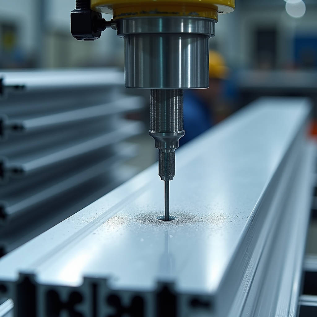
Aluminum Extrusion Drilling sits at the intersection of two critical manufacturing stages that determine whether a solid aluminium cladding panel fits perfectly on site or becomes a costly rework nightmare. When architects specify 3.0mm PVDF-coated solid aluminium sheets for a high-rise curtain wall, the drilling operations performed on the extruded sub-frame components—brackets, stiffeners, and mounting rails—directly control panel alignment, fastener integrity, and long-term structural performance. A misaligned hole in an aluminium extrusion mullion can cascade into visible panel gaps, water ingress, and eventual coating failure at stressed connection points. This article examines the precision drilling challenges specific to solid aluminium cladding systems, where 2.0mm to 3.0mm panels demand exacting tolerances from the supporting extrusion framework.
Why Solid Aluminium Cladding Demands Precision Drilling in Extruded Components
Solid aluminium cladding panels—typically 2.0mm, 2.5mm, or 3.0mm thick sheets with PVDF or FEVE fluoropolymer coatings—rely on an engineered sub-structure of extruded aluminium profiles. These extrusions, commonly 6063-T5 or 6061-T6 alloy, serve as vertical mullions, horizontal transoms, and panel stiffeners. The drilling operations performed on these extrusions create the connection points where cladding panels attach via stainless steel fasteners, rivets, or proprietary clip systems.
The tolerance chain matters. A typical curtain wall specification requires panel joint alignment within ±2mm across a 3-meter span. If the drilled holes in the extrusion sub-frame deviate by even 0.5mm, that error multiplies across the grid. By the time the tenth panel is installed, the cumulative misalignment can exceed 5mm—visually unacceptable and structurally compromised. For solid aluminium panels with folded edges and interlocking joints, this tolerance is non-negotiable.
Thermal movement adds another layer. Solid aluminium has a coefficient of thermal expansion approximately 23.8 × 10⁻⁶ /°C. A 4-meter extruded mullion subjected to a 60°C temperature swing (winter night to summer sun) expands by roughly 5.7mm. Drilled holes must accommodate this movement through slotted or oversized connections, and the drilling process itself must not introduce stress concentrations that accelerate fatigue cracking at these critical points.
Material Behavior: How 6063-T5 and 6061-T6 Extrusions Respond to Drilling
Not all aluminium extrusions drill the same way. The two alloys most common in cladding sub-structures exhibit distinct machining characteristics that directly affect hole quality, tool life, and downstream assembly.
6063-T5 is the workhorse of architectural extrusions. Its relatively low hardness (approximately 60 HB on the Brinell scale) and excellent formability make it forgiving during drilling. However, its softness also means it is prone to built-up edge (BUE) formation on the cutting tool. When aluminium adheres to the drill bit flute, the effective cutting diameter changes, producing oversized or tapered holes. For a cladding contractor, this means fasteners that feel tight during installation but lack full thread engagement—a hidden defect that may only surface during a windstorm.
6061-T6, with higher magnesium and silicon content, offers greater tensile strength (around 310 MPa versus 215 MPa for 6063-T5) and machines more cleanly. The chip breaks more readily, reducing BUE. However, its higher hardness (approximately 95 HB) demands sharper tooling and more rigid fixturing. A dull drill bit on 6061-T6 generates excessive heat that can locally anneal the material around the hole, softening the load-bearing zone. For solid aluminium cladding applications where wind loads can reach 2.5 kPa or more on tall buildings, this localized softening is unacceptable.
The table below summarizes the practical differences between these two alloys in drilling operations for cladding sub-structures:
| Property | 6063-T5 Extrusion | 6061-T6 Extrusion |
|---|---|---|
| Typical Brinell Hardness | 60 HB | 95 HB |
| Drilling Speed (HSS Tool, 6mm dia.) | 3,500–4,500 RPM | 2,800–3,500 RPM |
| Built-Up Edge Risk | High — requires polished flutes | Moderate — chip evacuation critical |
| Recommended Point Angle | 118° standard | 130–135° for reduced walking |
| Typical Cladding Application | Mullions, transoms, stiffeners | High-stress brackets, anchor points |
| Thread Strength (M8 tapped hole) | ~2.8 kN pull-out | ~4.1 kN pull-out |
Drilling Strategy for Cladding Sub-Structure Components
Pilot Hole Precision and Tap Drill Sizing
The relationship between a drilled hole and the fastener it receives is the single most consequential variable in cladding assembly. For tapped holes in aluminium extrusions—commonly M6, M8, and M10 for bracket connections—the tap drill size must produce approximately 65–75% thread engagement. This balances pull-out strength against the risk of tap breakage.
For an M8 × 1.25 thread in 6063-T5 extrusion, the correct tap drill diameter is 6.8mm. Drilling at 6.5mm increases thread engagement to roughly 82%, which sounds beneficial but dramatically raises tapping torque. In a production environment where hundreds of holes are tapped daily, this leads to tap fatigue, breakage, and costly rework. Conversely, a 7.0mm pilot hole reduces engagement to about 58%, producing threads that strip under the cyclic wind loading typical of high-rise facades.
Field experience from multiple cladding projects shows that thread stripping accounts for approximately 12% of all connection failures identified during façade inspections. The root cause is almost always incorrect tap drill sizing rather than material defects. For solid aluminium cladding systems where panels weigh 8–12 kg/m² for 3.0mm sheet, each connection point must reliably carry dead load, wind suction, and thermal cycling forces simultaneously.
CNC Drilling Versus Manual Operations: When Precision Becomes Non-Negotiable
For large-scale cladding projects—think 15,000 m² of solid aluminium panels on a commercial tower—CNC machining centers are the only practical approach to extrusion drilling. Modern 5-axis CNC machines with linear transfer automation can drill, tap, and mill aluminium extrusions in a single setup, maintaining positional accuracy within ±0.05mm. This is particularly critical for the interlocking panel systems where male-female joints between adjacent panels require sub-millimeter alignment of the supporting extrusion grid.
Manual drilling, even with jigs and fixtures, typically achieves ±0.3mm positional accuracy under ideal conditions. On a construction site with handheld tools, that tolerance widens to ±0.8mm or worse. The difference between CNC and manual drilling translates directly to visible panel alignment: a 0.5mm error at the extrusion level becomes a 1.5mm gap at the panel joint after factoring in panel fabrication tolerances and thermal movement allowances.
However, CNC drilling introduces its own challenges. The high spindle speeds (8,000–15,000 RPM for carbide tooling) generate significant heat. Without adequate coolant delivery—typically a mist or flood system using a water-soluble aluminium cutting fluid—the extrusion can experience localized thermal expansion during machining. A hole drilled at 15,000 RPM without coolant may measure 6.82mm when the extrusion is at 80°C, but contracts to 6.78mm when cooled to ambient temperature. That 0.04mm difference changes the fit class of an M8 fastener from a clearance fit to a transition fit, potentially causing assembly difficulties on site.
Tooling Selection: Carbide, HSS, and Coated Options for Aluminium Extrusion Drilling
The choice of drill bit material and geometry for aluminium extrusion drilling is not a trivial decision. It directly affects hole quality, production throughput, and per-hole cost—factors that compound across the thousands of holes in a typical cladding project.
High-speed steel (HSS) drill bits with polished flutes remain the most common choice for aluminium extrusion drilling in fabrication shops. They are cost-effective and forgiving when operators apply inconsistent feed pressure. However, HSS bits dull noticeably after 800–1,200 holes in 6063-T5, producing progressively larger holes as the cutting edges wear. For a project requiring 20,000 drilled holes, this means 15–20 tool changes and the associated downtime.
Solid carbide drill bits offer 3–5 times the tool life of HSS in aluminium, typically lasting 4,000–6,000 holes before requiring resharpening. Their higher stiffness reduces hole wandering on entry, critical when drilling thin-walled extrusion sections where the drill must engage a curved or irregular surface. The trade-off is cost: carbide bits cost 4–8 times more than HSS and are more brittle, making them unsuitable for handheld drilling where side loads are unpredictable.
Diamond-like carbon (DLC) coated tools represent the premium option. The coating's low coefficient of friction against aluminium (approximately 0.1) virtually eliminates built-up edge, and tool life can exceed 10,000 holes in 6061-T6. For high-volume cladding fabricators processing 50,000+ extrusion components annually, DLC-coated tooling delivers the lowest per-hole cost despite the higher upfront investment.
Common Defects in Aluminium Extrusion Drilling and Their Consequences for Cladding
Burr Formation and Coating Damage
Exit burrs are the most visible defect in aluminium extrusion drilling. When the drill breaks through the far side of an extrusion wall, the remaining material deforms plastically rather than shearing cleanly, leaving a raised ridge around the hole perimeter. For cladding sub-structures, these burrs create two problems.
First, a burr prevents the cladding panel from sitting flush against the extrusion. Even a 0.2mm burr creates a localized standoff that concentrates stress at the fastener, potentially cracking the PVDF coating around the panel's mounting hole. Once the coating is compromised, the aluminium substrate is exposed to atmospheric moisture, initiating filiform corrosion that spreads beneath the paint film.
Second, burrs on tapped holes interfere with fastener engagement. A bolt that encounters a burr during installation may cross-thread or produce a false torque reading—the installer feels resistance and stops turning, but the fastener is not fully seated. On a windy day, that partially engaged fastener becomes the first point of failure.
Deburring is therefore not optional. Mechanical deburring with a countersink tool or a specialized deburring blade should follow every drilling operation. For CNC-drilled extrusions, the deburring cycle can be integrated into the machining program, adding 1–2 seconds per hole but eliminating a significant quality risk.
Oversized Holes and Fastener Pull-Out
An oversized hole—typically caused by a worn drill bit, excessive spindle speed, or inadequate fixturing—reduces thread engagement and fastener pull-out strength. In a solid aluminium cladding system, pull-out failures manifest as loose panels that rattle in the wind, eventually fatiguing the remaining fasteners and potentially allowing panels to detach.
Testing data from ASTM E330 (structural performance of exterior windows, doors, skylights, and curtain walls) indicates that a properly tapped M8 hole in 6063-T5 extrusion with 3mm wall thickness achieves a pull-out strength of approximately 2.8 kN. If the hole is oversized by just 0.3mm, pull-out strength drops to roughly 1.9 kN—a 32% reduction. For a cladding panel subjected to design wind loads of 1.5 kPa (typical for a 30-meter building), each fastener may need to resist 0.8–1.2 kN. The safety margin shrinks rapidly when hole quality is compromised.
Thermal Considerations: Drilling Heat and Its Effect on Extrusion Integrity
Aluminium's high thermal conductivity—approximately 205 W/m·K for 6063 alloy—is a double-edged sword in drilling operations. Heat generated at the cutting interface dissipates rapidly through the workpiece, which prevents localized melting but can alter the temper condition of heat-treated extrusions.
The T5 temper in 6063 is achieved through artificial aging at approximately 175°C for 8 hours. If drilling friction raises the local temperature above 200°C, over-aging begins, reducing tensile strength. The affected zone is typically small—perhaps 1–2mm around the hole—but for closely spaced holes in a bracket or stiffener, the cumulative effect can be significant.
Practical mitigation strategies include:
- Using sharp tooling with correct geometry to minimize friction heating
- Applying a suitable aluminium cutting fluid—water-soluble synthetics perform well, providing both cooling and lubrication
- Limiting peck drilling depth to 3× drill diameter between coolant applications
- Monitoring chip color: straw-colored chips indicate temperatures around 180–200°C, while blue chips signal temperatures exceeding 300°C and immediate corrective action
For solid aluminium cladding fabricators, a supplier like Futeng® provides extrusions with documented temper certifications, ensuring that the as-received material properties are known and can be preserved through proper machining practices.
Fixture Design for Repeatable Aluminium Extrusion Drilling
Extrusion profiles present unique fixturing challenges due to their elongated shape and often complex cross-sections. A 6-meter length of mullion extrusion with multiple screw ports, gasket grooves, and thermal break channels requires fixturing that supports the profile without distorting it.
Pneumatic clamping systems with adjustable pressure settings are preferred over manual toggle clamps. Consistent clamping pressure—typically 0.4–0.6 MPa for 6063 extrusions—prevents the profile from shifting during drilling without causing plastic deformation. For thin-walled sections (wall thickness below 2mm), clamping pressure should be reduced to 0.2–0.3 MPa and distributed across multiple contact points.
Drilling jigs, such as the 3D-printed precision guides used for 40-series extrusions, can improve manual drilling accuracy significantly. A well-designed jig with hardened steel bushings at each hole location constrains the drill bit's entry angle and position, reducing hole wandering to approximately ±0.15mm. For on-site modifications where CNC equipment is unavailable, jigs are the difference between an acceptable repair and a compromised installation.
Corrosion Protection at Drilled Holes: A Critical Oversight
A drilled hole in an aluminium extrusion exposes bare metal that, in the presence of moisture and a dissimilar metal fastener, becomes a galvanic corrosion cell. Stainless steel fasteners (typically 304 or 316 grade) are cathodic relative to aluminium, and the small area of exposed aluminium around the hole—the anode—corrodes at an accelerated rate.
The standard mitigation is to apply a wet-install sealant or a zinc-rich primer to the drilled hole before fastener installation. For solid aluminium cladding systems in coastal environments (within 5km of saltwater), this step is mandatory. Without it, crevice corrosion can reduce the effective cross-section of the extrusion around fastener holes by 15–20% within 10 years, based on long-term exposure data from ASTM B117 salt spray testing correlated with field observations.
An alternative approach gaining traction in premium cladding systems is the use of stainless steel threaded inserts installed into the drilled holes. The insert provides a durable thread surface and isolates the aluminium from the fastener, but it adds approximately $0.15–0.30 per hole in material and installation cost. For a project with 50,000 connection points, this represents a $7,500–15,000 premium—significant but potentially justified for buildings in aggressive environments.
Quality Control: Inspection Protocols for Drilled Extrusions in Cladding
A systematic inspection protocol for drilled aluminium extrusions should address dimensional accuracy, surface condition, and thread integrity. The following workflow, adapted from practices aligned with AAMA guidelines for aluminium curtain wall components, provides a practical framework:
- First-article inspection: Measure hole positions on the first extrusion from each batch using a coordinate measuring machine (CMM) or calibrated digital calipers. Verify positional accuracy against the shop drawing within ±0.2mm.
- Hole diameter verification: Use go/no-go pin gauges to check every 50th hole. For an M8 clearance hole (typically 8.5mm diameter), the go gauge should pass freely and the no-go gauge should not enter.
- Thread inspection: For tapped holes, use a thread gauge to verify thread form and depth. A torque test on a sample of holes (1 per 100) confirms that the specified installation torque can be achieved without stripping.
- Burr check: Run a fingertip (gloved) across each hole. Any detectable burr triggers re-deburring of the entire batch.
- Documentation: Record inspection results in a batch traceability log that links each extrusion to its material certificate, drilling parameters, and operator.
For fabricators supplying solid aluminium cladding systems, this level of documentation is increasingly required by project specifications referencing ISO 9001 quality management standards. It also provides a defensible record in the event of a façade performance dispute.
Production Economics: Balancing Speed, Quality, and Cost in Extrusion Drilling
The economics of aluminium extrusion drilling for cladding projects involve a three-way trade-off between production speed, hole quality, and per-unit cost. Understanding this balance helps project managers make informed decisions about machining strategy.
CNC drilling with carbide tooling delivers the highest quality at approximately $0.08–0.12 per hole (including labor, machine amortization, and tooling). Manual drilling with HSS bits and jigs costs roughly $0.03–0.05 per hole but produces lower accuracy and higher scrap rates. For a mid-sized project with 30,000 holes, the CNC premium is $1,500–2,100—a small fraction of the total cladding package cost and easily justified by reduced rework and improved panel fit.
The real cost of poor drilling quality is not measured in dollars per hole but in site delays and rectification. A single day of curtain wall installation delay on a commercial project can cost $5,000–15,000 in labor, equipment rental, and schedule penalties. When misaligned holes force installers to re-drill on site—often without proper coolant or fixturing—the resulting quality degradation compounds across the entire façade.
Standards such as ASTM E330 for structural performance testing and AAMA 2605 for high-performance organic coatings on aluminium extrusions provide the performance benchmarks that drilling quality must support. A cladding system that meets these standards on paper can still fail in practice if the underlying extrusion drilling is inconsistent.
The path forward for solid aluminium cladding projects is clear: invest in precision drilling at the fabrication stage, verify quality through systematic inspection, and never compromise on the connection details that hold the entire façade together. When the wind blows at 50 meters above street level, the difference between a properly drilled extrusion and a marginal one is measured in millimeters—but the consequences span decades.