Aluminum Extrusion Milling How Precision Machining Determines Facade Panel Fit and Long Term Performance
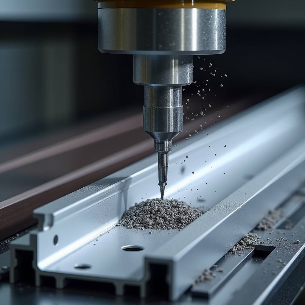
When a facade contractor submits shop drawings for a unitized curtain wall system, the conversation rarely starts with the aluminum panels themselves. It starts with the joints, the anchor channels, the perimeter closures — all the extruded aluminum profiles that frame and secure solid aluminium cladding panels into position. Aluminum Extrusion Milling is the machining process that transforms raw extruded profiles into these precision connection components. Every slot that accepts a 3.0mm solid aluminium panel edge, every drilled hole for a stainless steel bolt, every chamfered corner that allows thermal movement — these features do not come from the extrusion die. They come from CNC milling operations performed after extrusion, and the accuracy of that milling directly determines whether a panel sits flush on a building or develops a 4mm step that catches sunlight and triggers a defect claim.
Where Aluminum Extrusion Milling Fits in the Facade Supply Chain
To understand why this process matters to a project manager or a facade engineer, it helps to separate what an extrusion die does from what a CNC milling center does. An extrusion press pushes heated aluminum alloy through a shaped die to produce a continuous profile with a constant cross-section. That profile might be a mullion, a transom, a pressure plate, or a bracket channel. But the as-extruded length is essentially a raw bar. It has no mounting holes, no drainage slots, no notches for gasket insertion, and no milled pockets for hardware clearance.
Aluminum Extrusion Milling fills this gap. On a high-speed linear transfer machining center, the extruded bar is clamped, positioned, and sequenced through multiple operations: face milling, end milling, drilling, tapping, countersinking, and sometimes sawing to final length. The key distinction from general CNC machining is the fixturing. Extrusions are long, slender, and often asymmetric. Standard machine vises struggle with them. Dedicated extrusion milling machines use pneumatic clamping systems that grip the profile along its entire length without distorting the section. This matters for curtain wall applications because a distorted bracket channel can throw off panel alignment across an entire floor.
For solid aluminium cladding panels — typically 2.0mm, 2.5mm, or 3.0mm thick sheets with PVDF-coated surfaces — the interface with extruded components is where most installation failures originate. A panel does not fail in the middle of its flat surface. It fails at the routed return leg, at the rivet point, or at the clip slot. Each of those failure points involves an extruded profile that has been milled to receive the panel. If the milling tolerance is off by even 0.3mm, the panel edge sits proud or recessed, creating a shadow line that was never in the architect's intent.
CNC Operations That Define Aluminum Extrusion Milling for Facade Work
Not all milling operations are relevant to curtain wall and cladding applications. The ones that matter fall into a few specific categories, each with its own tolerance band and quality check.
Face Milling and Pocket Milling
Face milling removes material from the visible or functional face of an extrusion. In facade work, this is commonly used to create flat seating surfaces for gaskets, to mill pockets for hidden fasteners, or to reduce the profile height in specific zones where clearance is tight. The surface finish requirement here is typically 3.2 µm Ra or better, because a rough milled surface can abrade EPDM gaskets over time. Some specifications call for 1.6 µm Ra on gasket seating surfaces, which requires a finishing pass with a higher spindle speed and slower feed rate.
Drilling and Tapping
Drilling is the most common operation in Aluminum Extrusion Milling for cladding systems. Extruded mullions need through-holes for bolt connections at every floor slab. Pressure plates need staggered holes for self-tapping screws at 300mm centers. The challenge is not the drilling itself — it is maintaining hole position accuracy across a 6-meter extrusion length. Thermal expansion during machining can shift hole positions by 0.1mm to 0.2mm over a 6m bar. Good shops compensate for this by programming a thermal offset or by machining in temperature-controlled environments.
Tapping threads into aluminum extrusions requires attention to alloy grade. 6063-T5, the most common architectural extrusion alloy, machines easily but produces stringy chips that can clog threads. 6061-T6 machines cleaner and holds threads better, but it is more expensive and harder to extrude into complex shapes. For structural connections that will carry wind load, many engineers specify 6061-T6 for the extruded components and require thread inspection with go/no-go gauges after tapping.
End Milling and Notching
End milling cuts the profile ends to precise length and often creates notches for interlocking connections. A curtain wall mullion that meets a transom at a 90-degree intersection requires a clean end cut with squareness within 0.1mm across the profile width. Notching operations create cutouts that allow one profile to pass through another — common in stick-built curtain wall where vertical mullions run continuous and horizontal transoms are notched to fit between them.
Chamfering and Deburring
Chamfering removes sharp edges from milled features. This is not cosmetic. A sharp edge on an extruded aluminum bracket can cut into the PVDF coating of a solid aluminium cladding panel during installation or thermal cycling. The standard chamfer is 0.5mm × 45°, but some specifications require 1.0mm on edges that contact coated surfaces. Deburring follows every milling operation — automated brushing stations or manual deburring tools remove the thin aluminum burrs that form at the exit side of drilled holes and milled edges.
Alloy Selection for Extruded Components in Cladding Systems
The aluminum alloy used for the extrusion has a direct impact on milling behavior, tool life, and final part quality. The table below summarizes the alloys most commonly encountered in facade extrusion milling.
| Alloy | Temper | Typical Facade Use | Machinability Rating | Thread Holding | Corrosion Resistance |
|---|---|---|---|---|---|
| 6063 | T5 | Mullions, transoms, pressure plates | Good (70%) | Moderate | Excellent |
| 6063 | T6 | High-load mullions, anchor channels | Good (75%) | Good | Excellent |
| 6061 | T6 | Structural brackets, shear blocks | Good (80%) | Excellent | Very Good |
| 6005A | T6 | European-standard curtain wall profiles | Good (75%) | Good | Excellent |
| 6082 | T6 | Heavy structural connections | Fair (65%) | Excellent | Very Good |
Machinability ratings are relative to 6061-T6 as a baseline. The percentages reflect approximate cutting speed adjustments needed relative to 6061-T6 at the same tool life. 6082-T6, while strong, is harder on tooling and requires reduced speeds. Most architectural extrusion shops default to 6063-T5 or T6 because it balances extrudability, machinability, and cost. When a project specifies solid aluminium cladding panels at 3.0mm thickness with large spans, the supporting extrusion system often upgrades to 6061-T6 for the additional strength.
Tolerances That Actually Matter on Site
CNC machining centers can hold extremely tight tolerances in a lab setting. On a production floor running thousands of linear meters per shift, the tolerances that matter are the ones that affect panel fit-up and installation speed. Based on field experience across multiple high-rise facade projects, the following tolerance bands are what contractors should specify and verify:
- Hole position accuracy: ±0.15mm over any 1-meter length, ±0.5mm over a full 6-meter bar. This is tighter than the general ±0.25mm often quoted because hole misalignment compounds across multiple connection points.
- Slot width for panel edge insertion: +0.2mm / -0.0mm. A slot that is too narrow prevents panel insertion. A slot that is too wide allows panel rattling under wind load.
- End cut squareness: 0.1mm across the profile width. A mullion end that is not square creates a visible gap at the transom intersection.
- Milled surface finish: 3.2 µm Ra maximum on gasket-contact surfaces, 6.3 µm Ra on non-critical surfaces.
- Chamfer consistency: ±0.2mm on chamfer width. Inconsistent chamfers create uneven shadow lines.
These tolerances are not aspirational. They are achievable on properly maintained extrusion milling equipment from manufacturers like Elumatec, Fom Industrie, or Emmegi — brands commonly found in facade fabrication shops. The key is not the machine brand but the maintenance schedule and the quality of the cutting tools. A dull end mill produces burrs, poor surface finish, and dimensional drift. Shops that track tool life by cycle count rather than by visual inspection consistently produce better results.
Tooling Strategies for Aluminum Extrusion Milling
Aluminum is a soft, gummy metal compared to steel. It welds easily to cutting edges if the tool geometry, coating, and cutting parameters are not optimized. This is especially problematic in extrusion milling because the long, continuous cuts typical of profile machining generate heat that accelerates built-up edge formation.
Carbide Grades and Coatings
Solid carbide end mills are standard for aluminum extrusion work. The carbide grade should be micro-grain with high cobalt content (10-12%) for toughness, because interrupted cuts are common when milling slots and pockets in hollow profiles. Coatings matter: uncoated polished carbide works well for pure aluminum and soft alloys, but for 6061-T6 and 6082-T6, a ZrN (zirconium nitride) or TiB2 (titanium diboride) coating reduces aluminum adhesion and extends tool life by 30-50% compared to uncoated tools. DLC (diamond-like carbon) coatings are gaining traction but remain expensive for the shop-floor economics of facade fabrication.
Tool Geometry Specifics
For aluminum, high helix angles (35° to 45°) improve chip evacuation and reduce cutting forces. Two-flute or three-flute designs provide the chip clearance needed for the high material removal rates typical in extrusion milling. Single-flute cutters are sometimes used for deep slotting operations where chip evacuation is the limiting factor. The cutting edge should be sharp — a honed edge designed for steel will rub and smear aluminum rather than cut it cleanly.
Cutting Parameters
As a practical reference, milling 6063-T5 with a 10mm diameter carbide end mill typically runs at 12,000-18,000 RPM spindle speed and 2,000-4,000 mm/min feed rate, with depth of cut ranging from 2mm to 5mm depending on the operation. These numbers shift downward for 6061-T6 and further for 6082-T6. Coolant is mandatory — not primarily for lubrication but for chip flushing and thermal management. Mist coolant systems are common, but flood coolant provides better chip evacuation in deep pockets and tapped holes.
Quality Verification Methods
A facade contractor receiving machined extrusions from a fabricator should not rely on trust. Specific inspection protocols catch problems before they reach the installation floor.
First-article inspection is non-negotiable. Before a batch of 500 identical mullions goes into production, the first machined piece should be checked on a coordinate measuring machine or at minimum with calibrated digital height gauges and calipers. Every critical dimension — hole positions, slot widths, end cut lengths — should be recorded and compared against the shop drawing. This catches programming errors that would otherwise repeat across the entire batch.
In-process inspection uses go/no-go gauges for critical features. A simple gauge block that simulates the panel edge thickness can verify slot widths in seconds. Thread go/no-go gauges check tapped holes. These checks take minutes per shift and prevent hours of rework later.
For projects where solid aluminium cladding panels interface with extruded clips or carriers, a mock-up assembly test is the most reliable verification. Take one machined extrusion, attach one panel, and check the fit. This catches tolerance stack-up issues that individual measurements miss. A shop might produce extrusions within tolerance and panels within tolerance, yet the assembly still does not fit because the tolerances stack in the wrong direction. The mock-up reveals this before 2,000 units are machined.
Common Defects in Aluminum Extrusion Milling and Their Root Causes
Understanding what goes wrong helps procurement managers write better specifications and helps site teams identify problems faster.
- Burr formation at hole exits: Caused by dull tooling, excessive feed rate, or inadequate chip clearance. Burrs interfere with fastener seating and can cut gaskets. Solution: sharpen or replace tooling, adjust feed rate, ensure proper coolant flow.
- Hole position drift along the bar: Caused by thermal expansion during machining or by clamping distortion. The extrusion heats up as it is machined, and the thermal expansion shifts subsequent hole positions. Solution: machine in stages with cooling cycles, or program a thermal compensation offset.
- Chatter marks on milled surfaces: Caused by insufficient clamping rigidity, worn spindle bearings, or incorrect tool overhang. Chatter creates a wavy surface finish that exceeds the specified Ra value. Solution: reduce tool stick-out, check machine condition, adjust speeds and feeds.
- Thread stripping in tapped holes: Caused by wrong tap drill size, worn taps, or incorrect alloy selection. 6063-T5 threads are more prone to stripping than 6061-T6. Solution: verify tap drill diameter, use forming taps instead of cutting taps for stronger threads, or specify 6061-T6 for threaded connections.
- Profile distortion from clamping: Caused by excessive clamping pressure on thin-walled hollow extrusions. The profile springs back after machining, but the machined features are now in the wrong positions relative to the unclamped profile. Solution: use profile-specific clamping jaws, limit clamping pressure, and verify dimensions on unclamped parts.
Integrating Aluminum Extrusion Milling with Solid Aluminium Cladding Panel Systems
The connection between machined extrusions and solid aluminium panels is where the facade system either performs or fails. A 2.5mm or 3.0mm solid aluminium sheet, fabricated with routed and folded return edges, typically attaches to the building structure through a carrier frame made of extruded aluminum profiles. These profiles are milled to accept panel clips, to provide drainage paths, and to allow for thermal movement.
The panel clip slot is the most critical milled feature. It must be positioned accurately relative to the panel edge so that the clip engages fully without forcing the panel to bow. If the slot is milled 0.5mm too far from the panel plane, the clip applies a constant preload that can cause the panel to oil-can — a visible waviness in the flat surface that is unacceptable under most architectural specifications, particularly those referencing AAMA 609 and 610 for architectural aluminum finishes.
Drainage slots milled into horizontal extruded members are another detail that separates experienced fabricators from novices. Water that enters the cavity behind solid aluminium cladding panels must be directed out through weep holes. These are typically milled slots 6mm wide by 20mm long, positioned at the low points of horizontal profiles. The milling must not leave burrs that block water flow, and the slot edges must be deburred to prevent corrosion initiation. Some specifications require these slots to be milled before anodizing or coating, so the cut edges receive the same corrosion protection as the rest of the profile.
For projects where Futeng® supplies solid aluminium cladding panels, the coordination between panel fabrication tolerances and extrusion milling tolerances is addressed early in the shop drawing phase. The panel fabricator and the extrusion machinist work to the same datum scheme, ensuring that the panel return leg depth matches the clip slot depth with adequate clearance for thermal movement — typically 2mm to 3mm per panel edge depending on panel dimensions and expected temperature range.
Cost Factors in Aluminum Extrusion Milling for Facade Projects
Milling cost is driven by machine time, tooling consumption, and setup labor. Understanding these factors helps project teams budget accurately and identify where value engineering can reduce costs without compromising quality.
| Cost Factor | Impact Level | Typical Range | Notes |
|---|---|---|---|
| Machine hourly rate | High | $60-$120/hr | Varies by machine capability and region |
| Tooling cost per meter | Medium | $0.15-$0.50/m | Depends on alloy and operation complexity |
| Setup time per batch | Medium | 0.5-2.0 hours | Amortized over batch size; small batches cost more per unit |
| Programming time | Low-Medium | 1-4 hours per profile type | One-time cost; CAM programming from shop drawings |
| Inspection labor | Low | 5-10% of machine time | First-article and in-process checks |
| Rework/scrap | Variable | 1-5% of production | Higher for complex profiles with tight tolerances |
The most significant cost lever is batch size. Setting up a machining center for a specific extrusion profile takes time — loading the program, installing profile-specific jaws, running the first article, and verifying dimensions. That setup cost is the same whether the batch is 50 pieces or 500 pieces. For small batches, setup cost dominates. For large batches, machine cycle time and tooling cost dominate. This is why unitized curtain wall projects with repetitive profiles are more cost-efficient to machine than custom stick-built systems with many unique profile types.
Another cost consideration is whether to machine in-house or outsource. Facade fabricators that own extrusion milling centers can amortize the equipment cost across many projects. Those that outsource pay a markup on machine time but avoid capital investment. The break-even point depends on annual volume — roughly 50,000 linear meters of machined extrusion per year justifies in-house capability based on typical equipment costs and market rates for subcontract machining.
Specifying Aluminum Extrusion Milling in Project Documentation
Architects and facade engineers rarely specify milling operations directly. They specify the performance of the assembled system, and the fabricator determines how to achieve it. But there are points where the specification can and should address milling quality to avoid disputes later.
The relevant standards include ISO 2768 for general tolerances on machined parts, and ASTM B221 for aluminum alloy extruded bars, rods, wire, profiles, and tubes. Neither standard directly addresses the specific requirements of facade extrusion milling. A project specification should therefore include a dedicated section on machined extrusion tolerances, referencing the dimensional bands described earlier in this article.
The specification should also address surface treatment after milling. If extrusions are anodized after machining, the anodizing thickness (typically 15-20 microns for architectural applications per AAMA 611) must be accounted for in the milled dimensions. A slot milled to 3.0mm width will become approximately 2.96mm to 2.97mm after anodizing, because the anodic layer builds on both sides of the slot. For critical fit features, the milling program should compensate for this buildup.
For PVDF-coated extrusions, the coating thickness is typically 25-35 microns and is less uniform than anodizing. This makes dimensional compensation more challenging. The better approach is to mask critical fit surfaces before coating, or to machine after coating — though the latter risks damaging the coating and is generally avoided for architectural finishes.
Trends Shaping Aluminum Extrusion Milling in Facade Engineering
Several developments are changing how extrusion milling is done for cladding and curtain wall applications. Automated tool changers with 8-12 tool positions are becoming standard on new machining centers, reducing cycle times by eliminating manual tool changes between operations. Probing systems that measure the actual position of the clamped extrusion and adjust the machining coordinates accordingly are improving accuracy on long profiles where straightness tolerances from the extrusion press can be ±1mm over 6 meters.
On the software side, CAM programming is increasingly integrated with BIM models. The architect's Revit model contains the extrusion geometry and the connection points. That data can flow directly into CAM software, reducing programming time and eliminating transcription errors. This integration is not yet standard across the industry, but it is becoming a differentiator for fabricators who invest in digital workflows.
The push toward unitized facade systems is also changing extrusion milling requirements. Unitized panels are assembled in the factory, not on site. This means the extrusion machining must be right the first time — there is no site adjustment possible. The milling tolerances for unitized systems are therefore tighter than for stick-built systems, and the quality verification is more rigorous. This trend favors fabricators with modern CNC equipment and disciplined quality systems.
In facade engineering, the most expensive millimeter is the one that is wrong. Aluminum Extrusion Milling determines whether that millimeter is right or wrong across thousands of connection points on a single building.
Practical Recommendations for Project Teams
For the procurement manager or project engineer evaluating extrusion milling suppliers for a facade project, several practical steps reduce risk. Visit the fabrication shop and look at the machining center. Check the maintenance log. Ask about tool life tracking. Request a sample machined extrusion from a recent project and measure it. These steps reveal more about quality than any certificate or audit report.
For the architect or facade consultant, the key recommendation is to specify the dimensional tolerances that matter for panel fit-up, not generic machining tolerances. A drawing note that says "machine to ±0.1mm" is unrealistic and unenforceable for a 6-meter extrusion. A note that says "slot width for panel clip engagement: +0.2mm/-0.0mm, verified with go/no-go gauge" is specific, measurable, and achievable.
Aluminum Extrusion Milling is not the most visible part of a facade system. The public sees the panels, the glass, the overall form. But the people who install the system, who adjust the panels, who sign off on the quality — they see the milled slots, the drilled holes, the chamfered edges. They know whether the machining was done right within the first hour of installation. Getting it right means panels that fit the first time, joints that align, and a facade that performs for decades without a defect claim.