Aluminum Extrusion Notch Punching Tolerances Tooling and Cost Analysis for Curtain Wall Sub Frames
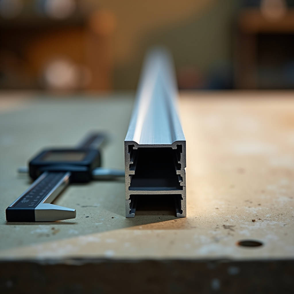
When a curtain wall contractor faces the task of joining two aluminum extrusion profiles at a 90-degree intersection, the difference between a clean, load-bearing connection and a misaligned joint often comes down to one process: Aluminum Extrusion Notch Punching. This secondary fabrication step removes material from the web or flange of an extruded profile so that a perpendicular member can slide through and lock into place. The notch must be geometrically precise — a deviation of 0.3 mm can turn a tight friction fit into a loose connection that requires shimming, welding, or complete rejection on site. For building envelope projects where solid aluminum cladding panels attach to extruded sub-frames, the quality of notch punching directly determines the flatness of the finished facade, the speed of on-site assembly, and the long-term resistance to wind-induced fatigue.
This article focuses on the engineering and procurement implications of notch punching in aluminum extrusions used for curtain wall framing and cladding support systems. The discussion covers tolerance standards, tooling selection, production throughput, and the cost-performance trade-offs that purchasing managers and facade engineers must evaluate when sourcing notched extrusion components from fabrication partners.
What Aluminum Extrusion Notch Punching Means in Facade Engineering
Aluminum Extrusion Notch Punching refers to the process of cutting a precisely shaped opening — rectangular, U-shaped, or custom-contoured — into the wall of an extruded aluminum profile using a punch and die set. Unlike drilling or milling, which remove material through rotary cutting, notch punching shears the aluminum in a single press stroke. The result is a clean-edged opening with minimal burr formation, provided the tooling clearance is correctly set for the alloy and wall thickness.
In curtain wall applications, notched extrusions serve as mullion-to-transom connection points, drainage channel intersections, and bracket mounting locations. A typical unitized curtain wall panel might require 12 to 20 notched connections per floor-height module. Multiply that across a 40-story commercial tower, and the cumulative number of notched features exceeds 50,000. At this scale, the speed and repeatability of the notch punching process become critical cost drivers.
The material being punched matters. Most architectural extrusions use 6063-T5 or 6063-T6 aluminum alloy, with wall thicknesses ranging from 1.5 mm to 3.0 mm for structural framing members. The punch-to-die clearance for 6063 aluminum should be maintained between 6% and 10% of material thickness — tighter than the 10% to 15% typically used for mild steel. Getting this clearance wrong produces excessive burr, accelerates tool wear, and can cause micro-cracking at the notch corners that propagates under cyclic wind loading.
Tooling Configurations and Their Impact on Notch Quality
The tooling setup for Aluminum Extrusion Notch Punching falls into three broad categories: dedicated single-station dies, multi-station progressive tooling, and CNC-guided punch heads integrated into automated processing lines. Each configuration carries distinct implications for tolerance control, production rate, and per-part cost.
Single-Station Dedicated Dies
For low-to-medium volume production — think 500 to 5,000 notched parts per batch — single-station tooling mounted on a hydraulic or pneumatic press offers the lowest upfront investment. A custom die set machined from D2 or A2 tool steel can deliver 50,000 to 100,000 cycles before requiring resharpening when punching 6063 aluminum. The key limitation is that each notch geometry requires a dedicated die. If a project involves three different notch sizes across mullion profiles, the operator must swap dies between runs, introducing setup time and the risk of alignment drift.
Single-station setups work well for bespoke facade projects where extrusion profiles are project-specific and batch sizes are modest. The per-notch cost, including labor, machine amortization, and tooling write-off, typically ranges from $0.08 to $0.25 depending on notch complexity and local labor rates.
Multi-Station Progressive Tooling
When production volumes exceed 10,000 identical notched parts, progressive tooling becomes economically compelling. A progressive die set incorporates multiple punching stations within a single tool, allowing the extrusion to advance through each station with every press stroke. Notching, hole punching, and even embossing can occur in sequence without part re-handling.
The throughput advantage is substantial. A well-designed progressive die running on a 60-ton mechanical press can produce 30 to 60 notched parts per minute, compared to 8 to 15 parts per minute for single-station operations. The trade-off is higher tooling cost — progressive dies for aluminum extrusions typically range from $8,000 to $25,000 depending on the number of stations and the complexity of the notch geometries. For projects consuming 50,000 or more parts, the per-unit tooling amortization drops below $0.05, making progressive tooling the clear cost leader.
CNC-Integrated Punch Heads
The most flexible approach integrates a programmable punch head into a CNC machining center designed for aluminum extrusions. These systems use a tool magazine holding multiple punch-and-die sets, switching between them under program control. The extrusion feeds through the machine on servo-driven rollers, and the control system positions the profile for each notch with positioning accuracy of ±0.1 mm.
CNC punch systems excel in high-mix, medium-volume production environments. A single machine can process 20 different extrusion profiles with varying notch patterns in a single shift, with changeover times measured in seconds rather than minutes. The capital cost is higher — a fully equipped CNC extrusion punch center typically costs $120,000 to $350,000 — but the elimination of dedicated tooling for each notch geometry makes this approach cost-effective for fabricators serving multiple facade projects simultaneously.
Tolerance Specifications That Matter for Curtain Wall Assembly
Notch punching tolerances affect curtain wall assembly in three measurable ways: extrusion fit-up, fastener alignment, and accumulated dimensional error across multiple connected components.
The primary tolerance to specify is notch width relative to the mating extrusion dimension. For a transom sliding into a mullion notch, the clearance should be 0.2 mm to 0.5 mm total — enough to allow assembly without hammering, but tight enough to prevent rattling under wind vibration. Achieving this requires the punch and die to be manufactured to a tolerance of ±0.05 mm on the cutting edges.
Notch position along the length of the extrusion is equally critical. A position tolerance of ±0.3 mm over a 3-meter length is achievable with properly fixtured single-station tooling and is standard for most architectural specifications. CNC-guided systems can hold ±0.15 mm, which becomes necessary when notches on adjacent mullions must align perfectly to receive a continuous transom.
Squareness of the notch bottom relative to the extrusion axis should be held within 0.1 mm across the notch width. A notch bottom that is not square causes the mating extrusion to sit at a slight angle, which compounds across the grid and manifests as visible misalignment in the finished facade.
| Tolerance Parameter | Standard Grade | Precision Grade | Measurement Method |
|---|---|---|---|
| Notch Width Clearance | 0.3 – 0.5 mm | 0.15 – 0.25 mm | Pin gauge / CMM |
| Notch Position (per 3 m) | ±0.3 mm | ±0.15 mm | Optical comparator |
| Notch Bottom Squareness | 0.15 mm | 0.08 mm | Dial indicator on surface plate |
| Burr Height (max) | 0.10 mm | 0.05 mm | Profilometer |
| Edge Radius (notch corner) | 0.5 mm min | 0.3 mm min | Radius gauge |
| Punch-to-Die Clearance | 8 – 10% of thickness | 6 – 8% of thickness | Feeler gauge / calculation |
The corner radius at the base of the notch deserves particular attention. Sharp internal corners act as stress concentrators. Under cyclic loading from wind pressure and suction, fatigue cracks can initiate at sharp notch corners and propagate through the extrusion web. A minimum corner radius of 0.5 mm is recommended for structural framing members per AAMA TIR-A9-14 guidelines. This radius is achieved by radiusing the punch corners during tool manufacture — a detail that adds cost to the die but significantly extends the service life of the extruded component.
Material Behavior During Notch Punching: What Engineers Need to Know
Aluminum behaves differently from steel during the punching process, and understanding these differences prevents costly specification errors. The 6063 alloy used in architectural extrusions has a tensile strength of 145–185 MPa in the T5 temper and 205–245 MPa in T6. The lower strength of T5 makes it easier to punch, requiring approximately 15% to 20% less tonnage than T6 material of the same thickness.
Punching tonnage for aluminum extrusions can be estimated using the formula: Force (kN) = Perimeter (mm) × Thickness (mm) × Shear Strength (MPa) / 1000. For 6063-T5 with a shear strength of approximately 130 MPa, a 30 mm × 20 mm rectangular notch (100 mm perimeter) in 2.5 mm wall thickness requires roughly 32.5 kN, or about 3.3 tons. Adding a 20% safety margin for tool wear and material variation brings the recommended press capacity to 4 tons for this notch. Most architectural notching operations use presses in the 10 to 30-ton range, which comfortably handles the majority of curtain wall extrusion profiles.
The punch entry side of the notch will exhibit a slight radius — typically 5% to 8% of material thickness — while the breakout side shows a sharper edge with minor burr. For architectural applications where the notched surface may be visible, the extrusion should be oriented so that the punch enters from the visible face. This produces a cleaner appearance on the side that matters. If the notch is hidden within an assembly, orientation can be optimized for tool life instead.
Work hardening at the notch edge is minimal with proper punch-to-die clearance. The affected zone extends approximately 0.5 mm to 1.0 mm from the cut edge, with hardness increase typically less than 15% above the base material. This is generally not significant for architectural applications, but it can affect subsequent bending or forming operations if the notch is located near a bend line.
Production Economics: Cost Drivers in Notch Punching Operations
For procurement managers evaluating quotes from extrusion fabrication suppliers, understanding the cost structure of Aluminum Extrusion Notch Punching enables more informed negotiation and value engineering decisions. The cost per notch breaks down into four primary components: tooling amortization, machine time, labor, and quality inspection.
Tooling cost is the most visible variable. A simple rectangular notch die for a single profile might cost $1,500 to $3,000 and last for 80,000 to 120,000 cycles before requiring refurbishment. Spread across a production run of 20,000 parts, the tooling cost per notch is $0.075 to $0.15. If the same die is used for a run of 100,000 parts, the per-notch tooling cost drops to $0.015 to $0.03. This is why consolidating notch designs across multiple projects — where feasible — yields significant cost savings.
Machine time cost depends on the press type and the cycle rate. A hydraulic press running at 15 strokes per minute with a labor and overhead rate of $90 per hour costs $0.10 per stroke. A mechanical press at 45 strokes per minute with the same hourly rate costs $0.033 per stroke. The difference of $0.067 per notch accumulates to $6,700 per 100,000 notches — enough to justify the higher capital cost of mechanical presses for high-volume programs.
Labor cost includes material handling, die setup, and in-process inspection. Automated feed systems reduce labor to approximately 0.2 minutes per part, while manual loading might require 0.5 to 1.0 minutes. At a labor rate of $25 per hour, the labor cost per part ranges from $0.08 to $0.42 depending on automation level.
Quality inspection adds approximately 5% to 10% to the total processing cost. First-article inspection using a coordinate measuring machine (CMM) or optical comparator, plus in-process checks every 200 to 500 parts, catches tool wear and alignment drift before they produce non-conforming parts. The cost of inspection is almost always lower than the cost of rework or rejection at the assembly stage.
Common Failure Modes and How to Prevent Them
Experience across multiple facade projects reveals several recurring failure modes in Aluminum Extrusion Notch Punching that procurement and quality teams should specifically address in supplier qualification and incoming inspection protocols.
Burr formation exceeding 0.10 mm is the most frequent issue. Burrs interfere with extrusion fit-up, create stress concentrations, and can damage protective anodizing or powder coating layers. The root cause is almost always excessive punch-to-die clearance, often resulting from die wear that has not been addressed through regular resharpening. A profilometer measurement of burr height on the first and last part of each production batch provides a simple quality gate.
Notch position drift occurs when the extrusion stop or positioning fixture shifts during a production run. A drift of 0.5 mm over 1,000 parts may seem minor, but when two such extrusions meet at a corner, the cumulative 1.0 mm offset creates a visible gap. Regular position verification using a go/no-go fixture or optical measurement every 200 parts prevents this issue from reaching the assembly stage.
Corner cracking at the notch base is a fatigue concern. Sharp punch corners, insufficient corner radius, or punching 6063-T6 material with a die designed for T5 can all produce micro-cracks. Dye penetrant inspection of first-article notches, followed by sectioning and microscopic examination of the notch corner, reveals whether the punch radius and clearance are appropriate for the alloy and temper being processed.
Die galling — the transfer of aluminum to the punch surface — accelerates wear and degrades notch quality. It occurs when the punch surface finish is too rough or when insufficient lubrication is used. A punch surface finish of Ra 0.2 μm or better, combined with a light application of vanishing oil or synthetic lubricant, minimizes galling on 6063 aluminum. Some fabricators use TiN (titanium nitride) coated punches, which reduce galling and extend tool life by 2x to 3x compared to uncoated tool steel.
Integrating Notch Punching with Solid Aluminum Cladding Panel Systems
Solid aluminum cladding panels — typically 2.0 mm, 2.5 mm, or 3.0 mm thick 3003-H14 or 5052-H32 alloy sheets with PVDF fluoropolymer coating — attach to the building structure through an extruded aluminum sub-frame system. The sub-frame consists of vertical mullions and horizontal transoms, both of which require notched intersections. The quality of these notched connections directly affects the installed flatness of the cladding panels.
A typical solid aluminum cladding panel measuring 1,200 mm × 3,000 mm is supported at four to six points along its perimeter by the sub-frame. If the sub-frame grid is not planar due to poorly notched connections, the panel will be forced into a slight twist or bow when fastened. The AAMA 609 standard for aluminum cladding installation specifies a maximum deviation of 3 mm over a 3-meter straightedge for the finished facade surface. Achieving this requires the sub-frame grid to be flat within 1.5 mm over the same distance, which in turn requires notch punching tolerances in the precision grade range described earlier.
For projects specifying PVDF-coated solid aluminum panels with 70% fluoropolymer resin content and a minimum dry film thickness of 30 microns per AAMA 2605, the sub-frame must also accommodate thermal movement. Aluminum expands at approximately 0.024 mm per meter per degree Celsius. A 3-meter mullion subjected to a 60°C temperature swing expands by 4.3 mm. Notch punching tolerances must account for this movement, typically by providing slotted connections at one end of each transom that allow sliding while maintaining structural engagement.
Fabricators like Futeng® that specialize in solid aluminum cladding systems often integrate notch punching into their in-house extrusion processing lines, ensuring that the sub-frame components and the cladding panels are produced under a unified quality system. This vertical integration reduces the risk of tolerance mismatch between the sub-frame and the panels it supports.
Quality Verification Protocols for Incoming Notched Extrusions
A structured incoming inspection protocol for notched aluminum extrusions protects the project schedule from the disruption of discovering dimensional issues during assembly. The following protocol, based on ISO 2859-1 sampling plans with normal inspection Level II, provides a practical framework for facade contractors and cladding system integrators.
For each batch of notched extrusions received, select a random sample based on the lot size per ISO 2859-1 tables. For a lot of 500 to 1,200 pieces, the sample size is 80 pieces. Perform the following checks on each sample piece:
- Verify notch width at three points along the notch using a calibrated pin gauge or digital caliper. The width must fall within the specified tolerance band.
- Measure notch position from the reference end of the extrusion using a steel rule or tape measure with 0.5 mm graduations. Position must be within ±0.5 mm of the drawing dimension for standard grade, or ±0.25 mm for precision grade.
- Check notch squareness by inserting a precision-ground square block into the notch and measuring any gap with a feeler gauge. Gap must not exceed 0.15 mm.
- Inspect the notch edges visually and with a fingernail test for burrs. Any burr that catches a fingernail or exceeds 0.10 mm measured height is cause for rejection.
- Examine notch corners at 10x magnification for cracks or excessive roughness. Any visible crack is grounds for lot rejection.
If two or fewer defective pieces are found in the sample, accept the lot. If three to five defectives are found, perform a second sample of the same size. If more than five defectives are found in the first sample, reject the lot outright. This protocol balances inspection cost against the risk of accepting non-conforming material.
Industry Standards Referenced in Notch Punching Specifications
Several standards provide the technical foundation for specifying and verifying notch punching quality in architectural aluminum extrusions. Project specifications should reference these standards explicitly to establish clear quality expectations with fabrication suppliers.
AAMA 609 covers the cleaning and maintenance of architectural aluminum, but its dimensional tolerance framework is widely referenced for cladding installation quality. ASTM B221 specifies tolerances for aluminum alloy extruded bars, rods, wire, profiles, and tubes, including straightness and twist limits that affect notch positioning accuracy. ISO 2768-1 provides general tolerances for linear and angular dimensions, applicable when specific notch tolerances are not called out on the engineering drawing. The Aluminum Association's Design Manual offers guidance on punch-to-die clearances and minimum bend radii for various aluminum alloys.
For projects in seismic zones, notch design must account for the inter-story drift requirements of ASCE 7. Slotted notch connections that allow 15 mm to 25 mm of movement in the plane of the facade are typically required for buildings with design drift ratios exceeding 1.5% of story height.
Making the Right Sourcing Decision
Selecting a fabrication partner for Aluminum Extrusion Notch Punching involves evaluating more than price per part. The supplier's tooling maintenance program, quality system maturity, and experience with architectural tolerance requirements all affect the delivered quality and project risk.
Ask potential suppliers to provide first-article inspection reports for a similar notch geometry produced within the past six months. Review their tool maintenance logs — a well-managed shop sharpens or replaces punches at intervals based on cycle count, not just when quality problems appear. Verify that their measurement equipment (calipers, CMM, optical comparators) carries current calibration certificates traceable to national standards.
For large-scale facade projects, consider qualifying two notch punching suppliers rather than relying on a single source. The qualification cost is modest compared to the schedule impact of a supply disruption. Maintain a small buffer stock of critical notched extrusions — typically 5% to 10% above the theoretical requirement — to absorb minor quality rejections without delaying installation.
The engineering reality is that notch punching, while a small step in the overall facade manufacturing sequence, has an outsized influence on assembly efficiency and finished quality. A 0.3 mm tolerance deviation in a single notch may seem trivial, but multiplied across thousands of connections in a building envelope, it determines whether the facade is installed in weeks or months, and whether the finished surface meets the architect's specification for flatness and alignment. Investing in precision at the notch punching stage pays returns throughout the project lifecycle.