Aluminum Extrusion Cutting Precision Methods for Rainscreen Facade Subframe Fabrication
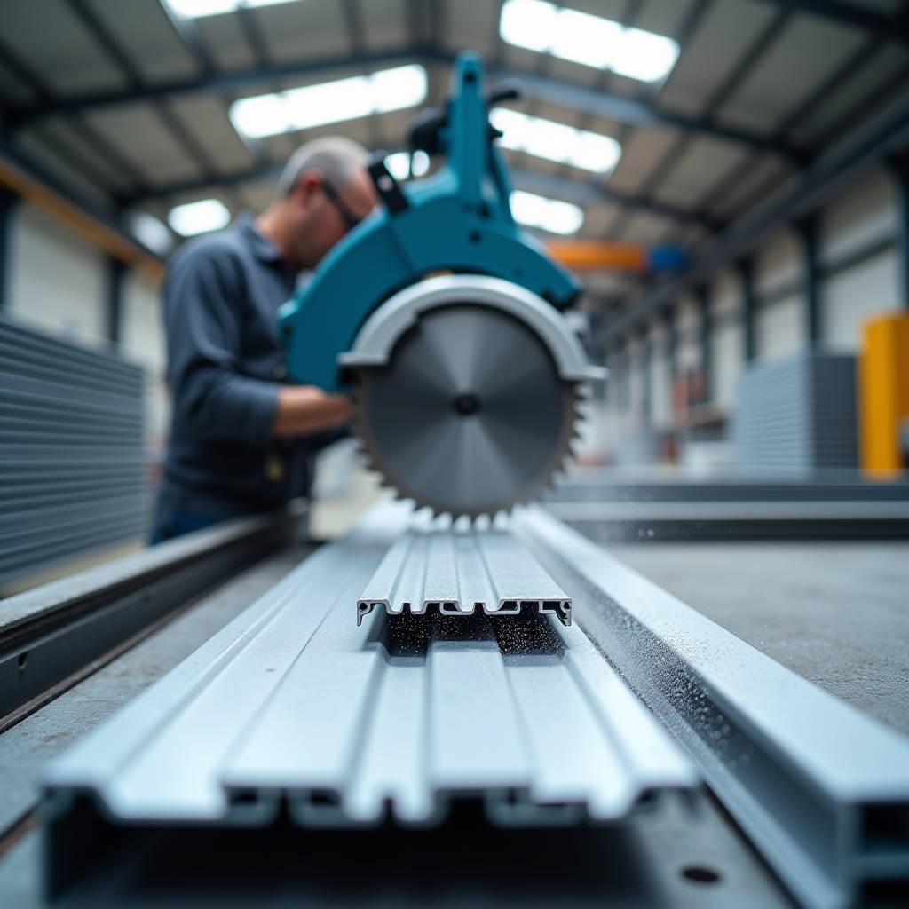
Getting a clean, dimensionally accurate cut on an aluminum extrusion is not the same as sawing through a piece of lumber. The hollow profiles, thin walls, and alloy composition of 6063-T5 or 6061-T6 extrusions demand a different approach entirely. When an extrusion is cut poorly, the resulting burr, drag line, or out-of-square edge cascades into assembly problems downstream: subframe connections that do not sit flush, gasket channels that tear seals, and visible joints that undermine the visual precision expected of a modern ventilated rainscreen facade. For contractors and fabricators handling solid aluminum cladding panels, Aluminum Extrusion Cutting is a gateway process. A botched cut on a perimeter extrusion or a mounting rail means rework, wasted material, and a schedule hit that no project manager wants to explain. This article examines the cutting methods, tooling choices, and quality control protocols that separate a fabrication-ready extrusion from scrap, with specific attention to the demands of architectural envelope systems.
Why Extrusion Cutting Quality Matters for Cladding Systems
In a rainscreen assembly, extruded aluminum components serve as the skeleton. Perimeter channels, Z-clips, hanging rails, and corner connectors are all extruded profiles. Their dimensional tolerances directly affect panel alignment across thousands of square meters of facade. A length error of 0.5 mm on a single rail may seem trivial, but accumulated across 40 floors of a commercial tower, it translates into panels that bind against each other, uneven shadow gaps, and stress concentrations that can cause PVDF coating to crack at fastener points.
The stakes are higher when extrusions interface with solid aluminum cladding panels. A 3.0 mm thick AA 5005 panel with a PVDF or FEVE coating has almost no give. If the supporting extrusion is cut 1 mm long, the panel either will not seat or will be forced into position, creating a permanent bow that catches light in a way no architect tolerates. This is why high-end fabricators, including those supplied by Futeng®, treat extrusion cutting as a precision machining step rather than a rough fabrication task.
Three specific quality metrics matter:
- Squareness: The cut face must be perpendicular to the extrusion axis within 0.1 mm across the profile width. An out-of-square cut creates a wedge-shaped gap at the joint.
- Burr height: Anything above 0.05 mm will interfere with mating parts. For anodized or powder-coated extrusions, burrs also create points where coating thickness drops to zero.
- Length tolerance: For architectural extrusions, ±0.2 mm is the practical target. Anything looser than ±0.5 mm will be visible in the installed system.
Cutting Methods: Mechanical vs. Thermal Approaches
The industry splits Aluminum Extrusion Cutting into two broad families: mechanical cutting, which uses a toothed blade or abrasive wheel to shear material away, and thermal cutting, which melts or vaporizes the aluminum. For architectural applications, mechanical cutting dominates because thermal methods introduce a heat-affected zone (HAZ) that alters the T5 or T6 temper of the extrusion near the cut edge. A softened HAZ can deform under structural load, compromising the mechanical interlock that rainscreen systems rely on.
Mechanical Cutting Methods
High-Speed Circular Sawing (Miter Saw / Upcut Saw) is the workhorse of extrusion fabrication. A carbide-tipped blade with a negative rake angle, typically 80 to 100 teeth on a 350 mm (14-inch) blade, spins at 2,800 to 4,000 RPM. The negative rake prevents the blade from grabbing the thin-walled extrusion and pulling it upward, which is the primary cause of kickback and edge chipping. Lubrication is non-negotiable. A mist coolant or stick lubricant applied to the blade reduces friction welding of aluminum chips to the carbide teeth, a phenomenon that dulls blades rapidly and produces ragged cuts.
Band Sawing is slower but generates less burr on thin-walled profiles. A bi-metal blade with 10-14 TPI (teeth per inch) running at 60-120 m/min surface speed works well for 6063 extrusions. Band saws are particularly useful for cutting bundled extrusions in a single pass, a productivity advantage when processing large quantities of identical rail lengths for a facade project.
CNC Router Cutting has gained traction for complex extrusion geometries. A single-flute carbide end mill, spinning at 18,000-24,000 RPM with a feed rate of 1,500-3,000 mm/min, can produce a finish-ready edge that requires no deburring. The trade-off is cycle time: a CNC router takes 3-5 times longer per cut than a circular saw. For high-mix, low-volume architectural work, the quality gain often justifies the speed penalty.
Thermal Cutting Methods
Laser Cutting of aluminum extrusions is technically feasible with a fiber laser of 2 kW or higher, but the HAZ extends 0.5-1.5 mm into the material, depending on cutting speed and assist gas. For non-structural trim pieces, this may be acceptable. For load-bearing rails, it is not. Plasma cutting is generally avoided for extrusions because the wide kerf (2-4 mm) and heavy dross make the cut edge unusable without secondary machining.
Tooling Selection: Blades, Lubrication, and Clamping
The blade is the single largest variable in cut quality. A triple-chip-grind (TCG) carbide blade designed specifically for non-ferrous metals is the standard. The tooth geometry alternates between a flat-top tooth that removes the bulk of material and a chamfered tooth that cleans the edges. For extrusions with wall thicknesses under 2.0 mm, a blade with 100+ teeth on a 350 mm diameter is recommended to ensure at least three teeth are engaged in the material at all times. Fewer teeth in contact means the extrusion vibrates between tooth impacts, producing a scalloped cut surface.
Lubrication choices break down into three categories:
- Mist coolant systems: A water-soluble oil diluted 10:1 and delivered as an aerosol. Best for high-volume production sawing. Keeps the blade cool and flushes chips away from the cut zone.
- Stick lubricants: A solid wax compound applied directly to the spinning blade before each cut. Simple, clean, and effective for intermittent use. Preferred by job-site crews cutting extrusions on a miter saw.
- Flood coolant: Used on CNC machining centers. Provides maximum cooling and chip evacuation but requires a full enclosure and filtration system.
Clamping deserves more attention than it usually receives. Aluminum extrusions are not rigid in the same way a solid bar is. The hollow cross-section deforms under clamping pressure, and if the extrusion is not fully supported along its length, the cut end will deflect downward as the blade exits, producing a burr on the bottom edge. The fix is a zero-clearance fence and a hold-down clamp positioned within 50 mm of the blade on both sides. For thin-walled extrusions (wall thickness below 1.5 mm), a sacrificial wooden insert in the fence prevents the material from collapsing into the gap between the fence and the blade.
Material Considerations: Alloy, Temper, and Wall Thickness
Not all aluminum extrusions cut the same way. The alloy and temper determine the material's machinability, which is a measure of how cleanly it shears under the cutting tool. The table below summarizes the key differences for alloys commonly encountered in architectural extrusion work.
| Alloy & Temper | Typical Application | Machinability Rating | Recommended Blade TPI | Burr Tendency |
|---|---|---|---|---|
| 6063-T5 | Architectural rails, mullions, trim | Good | 80-100 | Low |
| 6063-T6 | High-strength structural profiles | Fair | 100-120 | Moderate |
| 6061-T6 | Heavy structural connectors | Fair | 100-120 | High |
| 6082-T6 | Load-bearing brackets | Fair | 100-120 | High |
| 6005A-T6 | Transport and structural frames | Good | 80-100 | Low-Moderate |
6063-T5 is the most forgiving alloy for cutting. Its lower magnesium and silicon content compared to 6061 means the material is less gummy and produces shorter, more brittle chips that clear the kerf readily. 6061-T6, by contrast, is stickier and tends to produce long, stringy chips that wrap around the blade and score the cut surface. Using a blade with a higher tooth count and a more aggressive rake angle mitigates this, but the operator should expect to deburr 6061 cuts more thoroughly.
Wall thickness also dictates cutting parameters. An extrusion with 3.0 mm walls can handle a faster feed rate and a coarser blade than one with 1.2 mm walls. Thin-walled extrusions require a slower feed and a blade with minimal set to prevent the teeth from catching the edge and tearing it outward. The rule of thumb: feed rate in mm/min should be reduced by roughly 30% when wall thickness drops below 1.5 mm.
Burr Prevention and Deburring Techniques
Burrs form when the cutting tool exits the material and the last bit of metal, unsupported by the bulk of the workpiece, bends outward rather than being sheared cleanly. On an extrusion, burrs appear on the bottom edge of the cut (blade exit side) and along the internal web intersections. Preventing them is always cheaper than removing them afterward.
Five practices that minimize burr formation:
- Support the exit side: A zero-clearance insert on the saw table prevents the bottom edge from deflecting as the blade breaks through.
- Use a sharp blade: A dull blade rubs instead of cuts, generating heat and smearing material rather than shearing it. Blade life in architectural extrusion work is typically 5,000-8,000 cuts before resharpening.
- Optimize feed rate: Feeding too slowly causes rubbing and heat buildup. Feeding too fast overloads the tooth gullet and tears material. The sweet spot is a feed rate that produces small, curled chips that are silver in color, not golden or brown.
- Apply consistent lubrication: Dry cutting aluminum extrusions is a false economy. The blade loads up with aluminum within 50 cuts, and every subsequent cut degrades in quality.
- Clamp both sides of the cut: If the offcut is unsupported, it will droop as the cut completes, tearing the last few millimeters of material.
When deburring is necessary, a hand deburring tool with a swivel blade is the fastest option for external edges. For internal web intersections, a rotary file or a pneumatic pencil grinder with a carbide burr reaches areas that a hand tool cannot. The goal is to remove the burr without rounding over the edge, which would create a visible gap when the extrusion mates with a panel or connector.
Production-Scale Cutting: Workflow and Quality Control
A fabrication shop processing extrusions for a large facade project needs a systematic approach. The workflow typically breaks down into four stages:
Stage 1: Infeed and Measurement. Extrusions arrive in 6-meter lengths. A digital length stop with a positional accuracy of ±0.1 mm is set to the required cut length. Manual measurement with a tape measure introduces too much variability for architectural work. A roller conveyor supports the extrusion along its full length to prevent sagging.
Stage 2: Cutting. The saw operator loads the extrusion against the length stop, activates the clamps, and initiates the cut cycle. For a semi-automatic upcut saw, cycle time per cut is 8-12 seconds, including blade retraction. A single operator can process 250-350 cuts per hour, assuming consistent lengths.
Stage 3: Inspection. Every 50th piece is checked for length, squareness, and burr. A calibrated digital caliper and a machinist's square are the minimum inspection tools. For critical components, a go/no-go gauge machined to the exact profile cross-section verifies that the cut did not deform the extrusion.
Stage 4: Marking and Bundling. Each cut piece is labeled with a heat number, cut length, and part reference. Bundles are wrapped in VCI (volatile corrosion inhibitor) paper if the extrusions are mill-finish and will be stored before anodizing or coating.
For high-volume facade projects, automated sawing centers with magazine feeders and automatic length positioning can push output to 1,000+ cuts per hour. The capital cost is significant, but the per-cut cost drops by 40-60% compared to manual sawing, and the dimensional consistency improves measurably.
Common Cutting Defects and Their Root Causes
Even experienced operators encounter problems. Diagnosing the root cause quickly prevents a batch of defective parts from reaching the assembly floor. The following are the most frequent defects observed in Aluminum Extrusion Cutting for architectural applications:
- Drag lines (vertical scoring on the cut face): Caused by aluminum buildup on individual carbide teeth. The fix is to clean the blade with a resin solvent or replace it if the buildup has become welded to the tooth face.
- Chipped edges on the top surface: Indicates that the blade is too aggressive for the wall thickness. Switch to a blade with a higher tooth count or reduce the feed rate.
- Burr on the bottom edge only: The extrusion is not supported at the exit point. Install a zero-clearance insert or adjust the outfeed support.
- Out-of-square cut across the profile height: The saw head is not trammed correctly. The blade is tilted relative to the table surface. Re-tram the saw using a dial indicator.
- Discoloration (golden or brown cut surface): Excessive heat from a dull blade or insufficient lubrication. The material has reached temperatures above 200°C, which can locally anneal the T5 temper.
- Wavy cut surface: Vibration during the cut. Check that the extrusion is clamped firmly and that the blade arbor bearings are not worn.
Safety Protocols for Aluminum Extrusion Cutting
Aluminum chips are sharp, hot, and flammable in fine dust form. A shop that cuts extrusions all day accumulates chips that must be managed. The safety priorities are:
- Eye protection: A full-face shield in addition to safety glasses. A chip ejected from a 3,500 RPM blade has enough energy to penetrate skin.
- Hearing protection: Sustained noise levels of 95-105 dB(A) are typical for circular sawing of aluminum. Double protection (earplugs plus earmuffs) is recommended for all-day exposure.
- Chip management: Aluminum chips and dust are a Class D fire hazard when finely divided. Chip bins should be emptied daily and kept away from ignition sources. Wet chip collection systems are preferred for high-volume operations.
- Blade guarding: The saw blade guard must be functional and correctly adjusted. A significant percentage of saw injuries occur when the guard is tied back for "convenience."
- Glove policy: No gloves within 300 mm of a rotating blade. A glove caught by a saw blade pulls the hand in rather than protecting it.
According to the Aluminum Association's guidelines on fabrication safety, "mechanical cutting of aluminum extrusions shall be performed with properly guarded equipment and adequate chip containment to prevent slip hazards and combustible dust accumulation."
Cost Factors in Extrusion Cutting for Facade Projects
The cost of cutting aluminum extrusions for a facade project is not just the blade cost or the operator's hourly rate. It is the total cost of ownership of the cutting process, including scrap, rework, and downstream assembly problems. A breakdown of the cost drivers:
- Blade cost per cut: A quality 350 mm carbide blade costs $120-200 and lasts 5,000-8,000 cuts. Blade cost per cut is $0.02-0.04. A cheap blade that lasts 1,000 cuts and produces burrs that require 30 seconds of deburring per piece is far more expensive in total.
- Labor: At a fully burdened rate of $35-50/hour for a skilled fabricator, the labor cost per cut is $0.10-0.15 for manual sawing. Automation reduces this to $0.02-0.05.
- Scrap: A miscut extrusion for a custom facade profile often cannot be repurposed. At $8-15 per linear meter for architectural-grade extrusions, a 1% scrap rate on a project with 10,000 cuts adds $800-1,500 in material waste.
- Rework: An extrusion that passes inspection but is 0.3 mm long will cause fitment issues during panel installation. The cost of sending a technician to the site to file or re-cut an extrusion dwarfs the cost of getting it right in the shop.
For reference, the American Architectural Manufacturers Association (AAMA) publishes tolerance standards (AAMA 611 for anodized architectural aluminum) that specify permissible dimensional variation for fabricated extrusions. Meeting these standards requires a cutting process capability (Cpk) of at least 1.33, which translates to a process where the natural variation is only 75% of the tolerance band.
Integrating Extrusion Cutting with Panel Fabrication
In a facility that produces both solid aluminum cladding panels and the extrusion subframe components, cutting quality has a direct feedback loop. Panels are fabricated on CNC routers or turret punch presses to tolerances of ±0.1 mm. If the supporting extrusions are cut to ±0.5 mm, the assembly will not fit without forcing. The solution is to treat extrusion cutting as part of the same quality system that governs panel fabrication, with the same inspection frequency, the same calibrated measurement tools, and the same traceability requirements.
Some fabricators have moved to in-line cutting cells where extrusions are cut, deburred, and assembled into subframes within a single workflow. This eliminates the batch-and-queue delays that cause dimensional drift and miscommunication between cutting and assembly teams. The extrusion is cut, checked, and immediately test-fitted to a panel before the next piece is processed.
For projects specifying solid aluminum panels in 2.0 mm, 2.5 mm, or 3.0 mm thicknesses with PVDF or FEVE coatings, the extrusion cutting standard should be explicitly stated in the fabrication specification. A reference such as "extrusions shall be cut to length with a tolerance of ±0.2 mm, square within 0.1 mm, and free of burrs exceeding 0.05 mm" gives the fabricator a clear target and the inspector a clear pass/fail criterion.
Summary of Engineering Recommendations
The quality of Aluminum Extrusion Cutting reverberates through every subsequent stage of a rainscreen facade project. A clean, square, burr-free cut on an extrusion rail means a panel that hangs flat, a gasket that seals, and a joint that stays within tolerance for the 30-year design life of the building envelope. The key engineering takeaways are straightforward: use a carbide-tipped blade with a negative rake and a tooth count appropriate for the wall thickness, lubricate every cut, support the extrusion fully on both sides of the blade, and inspect frequently with calibrated instruments. The cost of doing it right in the shop is measured in cents per cut. The cost of fixing it on the scaffold is measured in hundreds of dollars per incident. For architects, specifiers, and contractors who demand that a facade perform as precisely as it looks, extrusion cutting is not a commodity operation. It is a core competency.