Aluminum Panel Profiling Engineering Tolerances Alloy Behavior and Coating Performance for Facade Cassettes
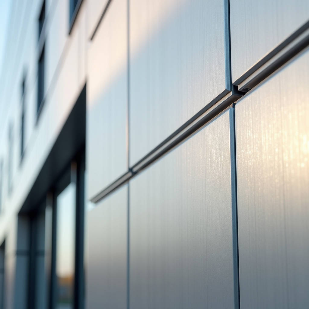
Aluminum panel profiling is the engineering discipline that determines how a flat aluminium sheet transforms into a structurally competent, weather-resistant facade element. It covers the controlled bending, folding, perforating, and edge-forming operations applied to solid aluminium panels—typically 2.0mm to 3.0mm gauge—before they reach the jobsite. The precision of these profiles dictates everything: joint alignment across a 40-meter elevation, the panel's resistance to wind-induced deflection, and whether the installed facade reads as a monolithic surface or a patchwork of misaligned edges. For architects and facade contractors, understanding profiling tolerances, fold radii, and the relationship between profile geometry and metal gauge is what separates a specification that can be built from one that generates RFIs and change orders.
What Profiling Means for Solid Aluminium Panels
Profiling is not extrusion. That distinction matters. Extruded aluminium profiles are pushed through a die in a semi-molten state, producing linear sections with consistent cross-sections—think mullions, transoms, and framing members. Aluminum panel profiling, by contrast, is a cold-forming or CNC-routed fabrication process applied to sheet aluminium that has already been rolled, leveled, and cut to size. The panel arrives as a flat blank. Profiling gives it three-dimensional geometry.
The most common profiling operations on solid aluminium cladding panels include:
- Edge returns and cassette folds: The panel perimeter is bent inward at 90° or variable angles to create a tray or cassette profile. This stiffens the panel and provides attachment points for hidden fixings.
- V-groove routing: A CNC router cuts a precise groove along the back face of the panel, leaving a thin material web. The panel is then folded along this groove to produce sharp external corners with minimal radius.
- Perforation and pattern profiling: Holes, slots, or custom cutouts are punched or routed into the panel face for acoustic performance, ventilation, or decorative effect.
- Stiffener integration: Profiled channels or ribs are formed into the panel back to increase span capability without adding material thickness.
Each of these operations interacts with the base metal's temper, the coating system, and the final installation method. Getting the profiling right means understanding those interactions.
Material Behavior During Profiling: Why Gauge and Temper Dictate Outcomes
Solid aluminium panels used in facade applications are typically supplied in the H14 or H24 temper range under ASTM B209—work-hardened to roughly half-hard condition. This temper provides a balance of formability and strength. When a 2.5mm panel in 3003-H14 alloy is bent to a 90° return, the outer fiber of the bend stretches while the inner fiber compresses. The bend radius relative to material thickness (the R/t ratio) determines whether the material cracks or forms cleanly.
For 3003-H14 aluminium, the minimum recommended inside bend radius for a 90° fold is approximately 1.5 times the material thickness. A 2.5mm panel therefore requires a minimum inside radius of roughly 3.75mm. Attempting a sharper bend—say, 1.0t—risks micro-cracking along the outer surface, which may not be visible immediately but will propagate under thermal cycling and wind loading over the building's service life.
For 5005-H14 and 5052-H32 alloys, which offer higher strength and better corrosion resistance in marine environments, the minimum bend radius increases to approximately 2.0t. This has direct implications for panel profiling: a cassette detail designed for 3003 may not be producible in 5052 without modifying the fold geometry or accepting a larger apparent joint.
Temperature matters too. In cold climates, aluminium's ductility decreases. A panel profiled in a heated factory in Shanghai may behave differently when installed in sub-zero conditions in Scandinavia. This is rarely discussed in specification documents but is well understood by fabricators who have dealt with warranty claims on cracked returns.
CNC Routing and V-Groove Profiling: The Precision Pathway
V-groove profiling has become the dominant method for producing sharp-edged cassette panels and complex folded geometries. The process involves mounting the flat aluminium blank on a CNC router bed and cutting a V-shaped groove along the bend line from the back face. The groove depth is controlled to leave a residual web—typically 0.3mm to 0.5mm for a 2.5mm panel—that acts as a hinge. The panel is then manually or mechanically folded along this groove.
The critical parameters in V-groove profiling are:
- Groove angle: Must match the intended fold angle. A 90° fold requires a 90° groove. Undercutting produces a gap at the external corner; overcutting causes interference.
- Web thickness: Too thin and the hinge tears during folding. Too thick and the fold radius becomes visible on the panel face, defeating the purpose of routing.
- Tool condition: A worn router bit produces burrs and inconsistent web thickness. Top-tier fabricators track tool life by linear meters cut and replace bits on a schedule, not when problems appear.
- Coating integrity: The groove must not penetrate the PVDF or powder coating on the face side. This requires precise depth control and, often, the use of depth-sensing probes on the CNC head.
For panels with PVDF coatings—typically 70% Kynar 500® or Hylar 5000® resin systems at 25-35 microns dry film thickness—the routing operation must also account for coating thickness. A 30-micron coating on a 2.5mm panel represents about 1.2% of the total thickness, but it sits entirely on the tension side of the fold. If the coating is brittle (as can happen with improperly cured PVDF), it will crack at the fold line regardless of the substrate condition.
Profile Geometry and Wind Load Performance
The profiling pattern on a solid aluminium panel directly influences its structural performance under wind load. A flat, unprofiled 2.5mm panel spanning 1,200mm between supports will deflect significantly more than the same panel with a 25mm edge return and a central stiffener rib. The return edge acts as a flange, increasing the panel's section modulus and moving the neutral axis away from the panel face.
The relationship between profile depth and stiffness follows beam theory: for a panel with edge returns, the effective moment of inertia increases roughly with the cube of the return depth. Doubling the return depth from 20mm to 40mm can increase stiffness by a factor of approximately 4 to 6, depending on the panel width and fixity conditions. This is why deep cassette profiles—50mm to 100mm returns—are specified for high-rise applications where wind pressures exceed 2.0 kPa.
Perforated panels present a different challenge. Openings reduce the panel's cross-sectional area and create stress concentrations around hole edges. A panel with 30% open area (by surface) may lose 40-50% of its bending stiffness compared to a solid panel of the same gauge. Profiling strategies for perforated panels often include:
- Increasing material gauge to compensate for stiffness loss.
- Adding unperforated margins and intermediate stiffener ribs.
- Using the perforation pattern itself as a profiling element—for example, embossed or louvered perforations that add local stiffness.
Thermal Movement and Profiling Tolerances
Aluminium has a coefficient of thermal expansion of approximately 23.4 × 10⁻⁶ /°C. A 4,000mm-long panel subjected to a 60°C temperature swing (from -10°C winter night to +50°C summer sun on a dark-colored facade) will expand by roughly 5.6mm. The profiling design must accommodate this movement without buckling the panel or overloading the fixings.
Three profiling strategies address thermal movement:
- Slotted fixing holes: The panel's top fixing points use round holes for location; lower points use vertically slotted holes that permit thermal elongation. The slot length is calculated from the expected movement range plus a safety margin.
- Profiled expansion joints: For long panel runs, the profiling incorporates a stepped or interlocking joint detail that allows adjacent panels to move independently while maintaining weather tightness.
- Controlled restraint: The panel profile includes stiffening elements that resist buckling while allowing in-plane expansion. This is particularly relevant for panels with deep returns that might otherwise bow outward when heated.
Fabrication tolerances for profiled panels are typically specified under AAMA 609.1 or the project-specific facade tolerance schedule. A well-profiled panel should achieve ±1.0mm on overall dimensions, ±0.5mm on fold locations, and ±0.5° on fold angles. Achieving these tolerances at production scale—hundreds or thousands of panels—requires CNC-controlled profiling equipment with regular calibration.
Coating Compatibility with Profiled Geometries
Not all coating systems perform equally on profiled panels. The profiling process subjects the coating to elongation, compression, and—in the case of routed folds—direct cutting. PVDF liquid coatings (AAMA 2605 compliant) offer excellent flexibility and can typically withstand the elongation at a 1.5t bend radius without cracking. Powder coatings (AAMA 2604) are generally more brittle and may require larger bend radii or post-forming application.
The table below summarizes coating performance characteristics relevant to profiling operations:
| Coating System | Standard | Typical DFT (microns) | Min. Bend Radius (R/t) | Profiling Suitability |
|---|---|---|---|---|
| PVDF (70% Kynar 500®) | AAMA 2605 | 25-35 | 1.5t | Excellent; suitable for V-groove and tight folds |
| PVDF (50% resin) | AAMA 2604 | 25-30 | 2.0t | Good; avoid radii below 2.0t |
| FEVE Powder | AAMA 2605 | 60-80 | 2.5t | Moderate; post-form application preferred |
| Polyester Powder | AAMA 2603 | 60-80 | 3.0t | Limited; best for flat or gently curved panels |
| Anodized (AA-M10C22A31) | AAMA 611 | 10-20 (oxide layer) | 2.0t | Good; but anodic film may craze at sharp folds |
For projects where profiling involves aggressive folds or complex geometries, PVDF liquid coating remains the most reliable choice. Fabricators such as Futeng® have developed proprietary pre-treatment sequences that enhance coating adhesion specifically at fold lines, reducing the incidence of micro-delamination that can lead to filiform corrosion.
Profiling for Rainscreen vs. Barrier Wall Systems
The profiling requirements differ fundamentally between rainscreen (ventilated) and barrier wall (sealed) facade systems. In a rainscreen, the profiled aluminium panel is the outer leaf of a cavity wall. The cavity is ventilated and pressure-equalized, so the panel profile does not need to provide a continuous air or water seal. This frees the profiling design to prioritize aesthetics and structural performance.
In a barrier wall system, the panel profile must incorporate interlocking joints with integrated gaskets or sealant grooves. The profiling must include:
- Precise gasket channels with controlled compression dimensions.
- Drainage paths formed into the panel edge profile.
- Overlap geometry that sheds water outward at horizontal joints.
Rainscreen profiling is generally simpler and faster to fabricate, which translates to lower cost per square meter. But it requires a properly designed cavity and backup wall—costs that fall elsewhere in the project budget. The choice between systems should be made early, because the profiling approach is not easily changed after fabrication begins.
Quality Control in Aluminum Panel Profiling
QC for profiled panels goes beyond dimensional checks. A comprehensive inspection protocol addresses:
- Fold angle accuracy: Measured with digital protractors at multiple points along each fold line. Variations exceeding 0.5° can cause visible joint misalignment across a facade module.
- Fold radius consistency: Checked with radius gauges. Inconsistent radii along a fold line indicate uneven tool pressure or material springback variation.
- Coating integrity at folds: Inspected under 10x magnification for micro-cracks, particularly at the outer surface of bends. A dye penetrant test may be used for critical applications.
- Flatness after profiling: Profiling can introduce residual stresses that cause the panel to bow or twist. Panels should be checked on a granite surface plate or with a coordinate measuring system.
- Perforation quality: Hole edges should be free of burrs and the perforation pattern should align with panel edges within ±1.0mm.
For projects requiring third-party verification, testing protocols from the American Architectural Manufacturers Association (AAMA) and ASTM International provide standardized methods. ASTM E283 and E331 address air and water penetration for profiled panel systems, while ASTM E330 covers structural performance under wind load.
Cost Drivers in Profiled Panel Fabrication
The profiling operation is typically the most labor-intensive and equipment-intensive stage of aluminium panel fabrication. Understanding what drives cost helps specifiers avoid unnecessary complexity:
- Number of folds per panel: Each fold requires a separate CNC setup, routing pass, and manual folding operation. A simple four-edge cassette requires four folds. A complex faceted panel might require 12 or more.
- Fold complexity: Simple 90° returns are fast. Compound angles, curved folds, and variable-depth returns require specialized tooling and slower production rates.
- Perforation density: High perforation percentages increase machine time and tool wear. Dense patterns with small holes take longer than sparse patterns with large holes.
- Material grade: Higher-strength alloys (5052, 5083) require more force to form and cause faster tool wear than 3003 or 1100 series.
- Coating sequence: Post-profiling coating application (where the panel is formed first and coated afterward) adds handling steps but eliminates the risk of coating damage at folds. Pre-coated profiling is faster but requires more careful handling.
A rule of thumb: a standard 4-sided cassette profile in 2.5mm 3003-H14 with PVDF pre-coat might cost 30-50% more than a flat panel of the same material, depending on volume and regional labor rates. Adding perforations, compound folds, or 5052 alloy can double or triple the profiling premium.
Digital Integration: From BIM to Profiling Machine
The most significant recent development in aluminum panel profiling is the direct digital link between building information models and CNC profiling equipment. A facade model authored in Revit or Rhino can now export panel geometry directly to CAM software, which generates toolpaths for the CNC router without manual programming.
This integration eliminates transcription errors, reduces lead times, and enables the fabrication of panels with geometries that would be impractical to program manually. It also supports parametric design workflows: an architect can adjust a panel profile in the BIM model, and the updated geometry flows through to the shop floor with minimal human intervention.
The ISO 19650 series on information management using BIM provides a framework for managing this digital workflow. For facade contractors, the key requirement is that the panel fabricator can accept and process the digital geometry files in the formats their CNC equipment requires—typically DXF, STEP, or native CAM formats.
Common Profiling Defects and Their Causes
Even experienced fabricators encounter profiling defects. Recognizing these early prevents costly site rectification:
- Springback: The panel partially returns to its original shape after folding, resulting in an angle larger than specified. This is inherent to cold-formed aluminium and must be compensated by over-bending. The springback allowance depends on alloy, temper, and bend radius—typically 2° to 5° for 3003-H14 at 1.5t radius.
- Oil canning: Visible waviness or buckling in the panel face, caused by residual stresses from the profiling operation or from thermal expansion restraint. Reducing oil canning requires careful control of fold sequencing and, in some cases, stress-relief heat treatment.
- Corner cracking: Cracks at the intersection of two folded edges, where material is subjected to biaxial tension. Mitigation includes notching the corner before folding and controlling the fold sequence.
- Coating peel at edges: The coating delaminates from the substrate near cut or folded edges, typically due to inadequate pre-treatment or excessive mechanical stress. ASTM D3359 cross-hatch adhesion testing can identify panels at risk before they leave the factory.
Addressing these defects at the profiling stage is far less expensive than replacing panels after installation. A competent fabricator maintains a defect library and continuously refines profiling parameters based on production experience.
Specifying Aluminum Panel Profiling: What to Include
A specification that addresses profiling directly will produce better pricing and fewer disputes than one that leaves profiling to the fabricator's discretion. Key items to specify include:
- Alloy and temper: Reference ASTM B209 and specify the acceptable alloy range (e.g., 3003-H14, 5005-H14, or 5052-H32).
- Panel gauge: State the nominal thickness and tolerance. For solid aluminium cladding, 2.0mm, 2.5mm, and 3.0mm are the standard gauges.
- Fold geometry: Provide drawings showing return depths, fold angles, and corner details. Indicate whether V-groove routing is permitted or required.
- Perforation pattern: If applicable, specify the hole diameter, spacing, open area percentage, and edge margin.
- Coating system: Reference AAMA 2605, 2604, or 2603 as appropriate, and state whether coating is to be applied before or after profiling.
- Tolerances: Reference AAMA 609.1 or provide project-specific values for dimensional, angular, and flatness tolerances.
- QC requirements: Specify inspection frequency, measurement methods, and acceptance criteria.
The Metal Construction Association (MCA) publishes technical guides that can assist in developing profiling specifications for metal wall panels.
Aluminum panel profiling is where the architect's design intent meets the realities of material behavior, fabrication economics, and site installation. The best profiling solutions are those that resolve all three constraints simultaneously—producing panels that look precisely as designed, can be fabricated efficiently at the required volume, and install without field modification.
For project teams navigating the specification of profiled solid aluminium panels, the sequence of decisions matters. Start with the performance requirements—wind load, thermal movement, water management. Choose the alloy and gauge that satisfy those requirements. Design the profile geometry to work within the material's formability limits. Specify the coating system that will survive the profiling operation and the building's environmental exposure. And engage with a fabricator who can demonstrate documented quality control over every profiling parameter discussed here. The result is a facade that performs as engineered and looks as intended, for the full design life of the building.