Aluminum Corner Assembly Engineering for Solid Aluminium Cladding Facade Performance
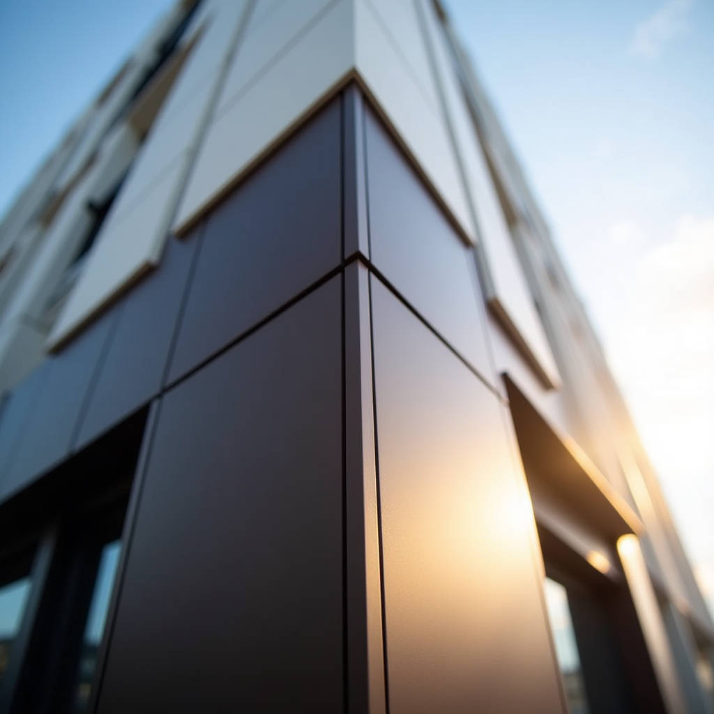
When a facade contractor calls three months after handover reporting water staining around a building's corners, the root cause almost always traces back to one overlooked detail: the Aluminum Corner Assembly. This is not about the panel itself. It is about how two solid aluminium cladding panels meet at a 90-degree external angle, how the substructure handles thermal movement at that junction, and how the sealant joint is engineered to survive decades of UV exposure, wind-driven rain, and cyclic expansion. A poorly executed Aluminum Corner Assembly can turn a premium 3.0mm PVDF-coated solid aluminium facade into a liability. Done correctly, it disappears visually while performing mechanically for 30 years or more. This article examines the engineering decisions that separate a corner assembly that leaks from one that lasts, drawing on field data from commercial projects across Southeast Asia, the Middle East, and North America.
What Actually Fails at a Corner
Most post-installation facade failures concentrate at corners. The reason is not material quality. It is geometry. A flat wall panel expands and contracts in one plane. A corner assembly involves two panels meeting at an angle, each moving independently, with a sealant joint bridging the gap. The differential movement between the two panels, combined with wind pressure that peaks at building corners (typically 1.5 to 2.0 times the pressure on flat walls per ASCE 7-22), creates a stress concentration that no flat-wall detail experiences.
Three failure modes dominate:
- Sealant cohesive failure: The silicone tears within its body, not at the bond line. This usually means the joint width was insufficient for the calculated movement.
- Adhesive failure at the substrate: The sealant peels cleanly from the aluminium. This points to inadequate surface preparation, wrong primer, or contamination during installation.
- Substructure corrosion at the corner: Galvanic reaction between the aluminium panel and a dissimilar metal bracket, accelerated by trapped moisture at the corner junction.
Each of these failures can be prevented, but only if the Aluminum Corner Assembly is treated as an engineered system rather than a detail left to site workers to figure out.
Thermal Movement: The Numbers That Drive Corner Design
Solid aluminium has a coefficient of linear thermal expansion of approximately 2.4 × 10⁻⁵ per °C. A 3.0mm thick solid aluminium panel spanning 1,200mm in length, subjected to a 70°C temperature swing (from -10°C winter night to 60°C summer sun on a dark PVDF coating), will expand by roughly 2.0mm. That does not sound dramatic. But at a corner, two panels each moving 2.0mm in different directions create a combined differential that can exceed 3.5mm at the joint.
If the sealant joint is designed at 15mm width — a common architectural specification — and the sealant has a movement capability of ±25%, the joint can accommodate 3.75mm of movement. That leaves a margin of just 0.25mm. Factor in construction tolerances (±3mm on panel positioning is standard under AAMA 501.1), and the joint is already beyond its design capacity before the building experiences its first summer.
This is why experienced facade engineers specify minimum 20mm sealant joints at external corners for solid aluminium panels over 1,000mm in any dimension. The math is straightforward, but the discipline to enforce it on site is rare.
Sealant Selection: Not All Silicones Are Equal
The sealant in an Aluminum Corner Assembly performs two conflicting functions: it must bond tenaciously to the PVDF-coated aluminium substrate while remaining flexible enough to absorb movement. PVDF coatings, particularly those with high fluoropolymer content (70% PVDF resin per AAMA 2605), present a low-surface-energy substrate that challenges adhesion.
The industry standard for structural silicone in facade joints is ASTM C920, but the critical sub-classification is Type S (single-component) versus Type M (multi-component), and Grade NS (non-sag) for vertical joints. For corner assemblies on high-rise buildings, a medium-modulus silicone with ±50% movement capability is preferred over high-modulus options. The lower modulus reduces stress transmission to the bond line.
Below is a comparison of sealant types commonly specified for external corner joints on solid aluminium cladding:
| Sealant Type | Movement Capability | Service Life (Est.) | Adhesion to PVDF | Typical Joint Width (Min.) |
|---|---|---|---|---|
| Neutral Cure Silicone (Medium Modulus) | ±50% | 20-30 years | Excellent (with primer) | 15mm |
| Neutral Cure Silicone (High Modulus) | ±25% | 20-30 years | Good (with primer) | 20mm |
| Hybrid Polymer (MS Polymer) | ±25% | 15-20 years | Moderate | 20mm |
| Acrylic Sealant | ±10% | 5-10 years | Poor | Not recommended |
The data makes a clear case: medium-modulus neutral-cure silicone, properly primed, is the only defensible choice for a long-service-life Aluminum Corner Assembly on solid aluminium panels. The cost difference between a high-quality silicone and a budget alternative is typically less than $2 per linear meter of corner joint. The cost of a failed joint requiring scaffold access and re-sealing on a 20-story building can exceed $200 per linear meter.
Substructure Design at Corners: The Hidden Half of the Assembly
The visible corner joint is only half the story. Behind the panels, the aluminium substructure must transfer wind loads from two perpendicular planes into the building structure while accommodating the same thermal movement the sealant handles. The most common mistake is using a single continuous angle bracket that rigidly connects both panels to the same vertical rail. This creates a fixed point that forces all movement into the sealant joint.
The correct approach is a split-substructure detail. Each panel at the corner is supported by its own independent vertical rail, with the two rails separated by a gap of 10-15mm. This allows each panel to move independently, reducing the differential movement at the sealant joint by approximately 40-60% compared to a rigidly connected corner.
For solid aluminium panels in 2.5mm or 3.0mm thickness, the corner substructure must also address the following:
- Bracket material compatibility: All brackets, screws, and fasteners in contact with the aluminium panel must be either aluminium (6063-T5 or 6061-T6) or stainless steel (304 or 316 grade). Galvanized steel brackets in contact with aluminium will initiate galvanic corrosion within 12-24 months in coastal environments, per ISO 9223 corrosivity classifications for C3 and above.
- Thermal break at the corner: A 2mm EPDM gasket between the panel return leg and the bracket prevents metal-to-metal contact and reduces thermal bridging.
- Fixing slot allowance: Slotted holes on the panel fixing brackets should provide at least ±3mm of adjustment in both horizontal and vertical directions to absorb fabrication and installation tolerances.
Fabrication Tolerances: Why the Factory Matters
An Aluminum Corner Assembly is only as precise as the panels that meet at the corner. If one panel is 2mm longer than specified, the sealant joint on site becomes 2mm narrower than designed. If the panel edge is not cut square, the joint width varies along its length, creating stress points where sealant movement capacity is locally exceeded.
The key fabrication tolerances for solid aluminium panels destined for corner assemblies are:
- Panel length and width: ±1.0mm (per ASTM B209 for aluminium sheet and plate)
- Squareness of cut: Diagonal difference ≤ 2.0mm
- Edge straightness: ≤ 0.5mm deviation per 1,000mm of edge length
- Fold/return leg angle: 90° ± 0.5°
These tolerances are achievable with CNC routing and press brake folding, but they require a factory that invests in calibrated equipment and quality control at each production stage. Suppliers like Futeng® operating with in-house CNC routing centers and automated folding lines can hold these tolerances consistently across production runs of 500 or 5,000 panels. The alternative — manual cutting and folding — introduces variability that site teams cannot fully compensate for, no matter how skilled the installers.
Wind Load Concentration at Building Corners
The building corner is where wind pressures peak. According to wind tunnel studies and the pressure coefficient (Cp) data in ASCE 7-22, the negative pressure (suction) at a building corner zone can be 2.5 to 3.0 times higher than the average wall pressure. For a building in a 150 mph (67 m/s) wind zone, the corner zone design pressure can reach 4.5 kPa or more.
For the Aluminum Corner Assembly, this has two direct implications:
- Panel thickness at corners: While the main wall area may be adequately served by 2.0mm solid aluminium, the corner panels should be upgraded to 2.5mm or 3.0mm to resist higher bending stresses. The incremental cost is modest — approximately 15-20% more material for the corner panels — but the improvement in wind load resistance is significant.
- Fixing spacing at corners: The standard fixing spacing of 400-600mm on center should be reduced to 250-350mm for corner panels and the adjacent panels within 1.5m of the corner. This denser fixing pattern prevents panel flutter and reduces the cyclic loading that fatigues sealant joints over time.
Wind tunnel testing consistently shows that the corner zone — defined as the building perimeter within a distance equal to 10% of the building's least horizontal dimension — requires enhanced fixing and thicker panels. This is not a recommendation; it is a structural requirement under most international building codes.
Installation Sequence: The Site Reality
Even the best-engineered Aluminum Corner Assembly fails if installed in the wrong sequence. The correct sequence is:
- Install vertical substructure rails, verifying plumb within ±2mm over the full height.
- Mount the corner bracket assemblies on both sides, leaving the bracket-to-rail bolts finger-tight.
- Hang the first corner panel, align to grid lines, and tighten bracket bolts.
- Hang the adjacent panel on the perpendicular face, adjust to achieve the specified joint width (using joint spacers), then tighten.
- Install backer rod to the correct depth (typically 50% of joint width).
- Apply primer to both panel edges if specified by the sealant manufacturer.
- Gun the sealant in a single continuous pass, tool within the open time, and protect from rain for the curing period (typically 24-72 hours depending on product).
The most common site error is step 4: installers tighten the second panel without checking the joint width, resulting in joints that taper from 20mm at the top to 12mm at the bottom. The sealant cannot compensate for this. A 12mm joint with ±25% movement capability accommodates 3mm of movement — less than the thermal movement of a single panel on a hot day.
Water Management: The Pressure-Equalized Corner
A properly designed Aluminum Corner Assembly for solid aluminium cladding should incorporate pressure equalization. The principle is straightforward: allow air to enter the cavity behind the panels through openings at the bottom of the facade, equalizing the air pressure inside and outside the panel. This reduces the pressure differential that drives rainwater through the sealant joint.
At the corner, the pressure-equalized cavity must be continuous around the angle. This means the corner substructure must not block airflow between the two perpendicular cavity zones. A gap of at least 25mm should be maintained between the corner bracket assembly and any cavity closure profiles.
Additionally, a secondary drainage path should be detailed at the corner. Any water that penetrates the outer seal must be directed downward and out through weep holes at each floor level. The corner is the most likely point for water ingress, so the drainage path at the corner must be oversized relative to the flat wall — typically 150% of the standard weep hole area.
Coastal and Industrial Environments: Accelerated Degradation
Corner assemblies in coastal environments (within 5km of salt water) or industrial zones face accelerated degradation. The combination of salt spray, higher humidity, and aggressive airborne contaminants attacks both the sealant and the aluminium substrate.
For these environments, the following upgrades are recommended:
- PVDF coating: 4-coat system (primer + color + clear + backer) with minimum 35 microns total dry film thickness, exceeding the AAMA 2605 minimum of 30 microns.
- Sealant: Specify a silicone with documented salt-spray resistance per ASTM B117, with no loss of adhesion after 5,000 hours of exposure.
- Fasteners: All visible fasteners and those within 300mm of the corner joint should be 316 stainless steel. 304 grade is insufficient for coastal exposure beyond 1km from the shoreline.
- Panel edge treatment: Cut edges of solid aluminium panels at the corner should receive a touch-up coating of PVDF-compatible primer to seal the exposed aluminium substrate before the panel is installed.
Quality Verification: What to Check Before Signing Off
Before the scaffolding comes down, the Aluminum Corner Assembly should be inspected against a defined checklist. The following items are non-negotiable:
- Joint width measurement: Measure at top, middle, and bottom of each corner joint. Variation must not exceed ±2mm from the specified width.
- Sealant adhesion test: Conduct a field adhesion test per ASTM C1521 on one corner joint per elevation. The sealant should exhibit cohesive failure (tearing within itself), not adhesive failure (peeling from the substrate).
- Water spray test: Perform a calibrated water spray test per AAMA 501.2 on a representative corner zone. No water penetration to the interior after 15 minutes of continuous spray at the specified pressure differential.
- Fixing inspection: Randomly remove 5% of corner panels to verify bracket type, fastener grade, and the presence of EPDM isolation pads at all metal-to-metal contact points.
These tests cost time and money, but they cost far less than a full scaffold re-erection and facade repair two years after practical completion.
Making the Corner Assembly Work Across Project Scales
The principles of a sound Aluminum Corner Assembly do not change with project size, but the execution challenges do. A 500m² retail facade with 20 corner panels is manageable with close site supervision. A 50,000m² mixed-use tower with 400 corner panels demands a different approach: factory-pre-assembled corner units, where the two panels are pre-fitted to a shared subframe in the factory, with the sealant joint pre-applied under controlled conditions, leaving only the subframe-to-structure connection for site work.
This approach shifts the quality-critical operations from a windy, dusty construction site to a clean factory environment. The cost premium for pre-assembled corner units is typically 10-15% over conventional site assembly, but the reduction in site labor, sealant waste, and rework often offsets the premium entirely. On projects where the Aluminum Corner Assembly is a known risk item, pre-assembly is the most reliable path to a watertight facade.
The corner of a building is where the architecture meets the engineering. It is the detail that photographers capture and the detail that building owners worry about. Getting it right requires no exotic materials or unproven technologies. It requires understanding the numbers behind thermal movement, specifying the right sealant for the substrate, designing a substructure that respects independent panel movement, and enforcing fabrication tolerances that make the site work predictable. Solid aluminium cladding panels, manufactured to the tolerances described here and supported by a properly detailed corner assembly, will perform for decades with minimal maintenance. The alternative — treating the corner as just another joint — is a decision that facade contractors and building owners will regret long before the defects liability period expires.