Aluminum Micro Perforation Manufacturing Limits and Facade Engineering Reality
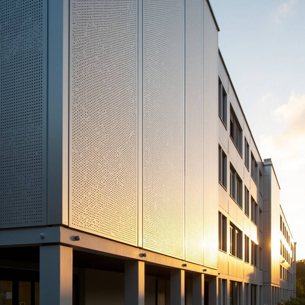
When a facade engineer stares at a specification sheet demanding 35% open area with sub-2mm perforations on a 3.0mm solid aluminum panel, the conversation shifts instantly from generic cladding to precision manufacturing. Aluminum Micro Perforation is not simply punching small holes into metal. It is a tightly controlled industrial process where hole diameter, pitch geometry, edge quality, and post-perforation flatness determine whether a panel performs acoustically, survives wind loads, and looks clean after five years of weather exposure. Architects chasing transparency effects, acoustic consultants chasing NRC values, and contractors chasing predictable lead times all converge on the same question: how small can the holes go before the panel stops behaving like a structural skin and starts behaving like a sieve? This article examines the manufacturing thresholds, mechanical compromises, acoustic physics, and corrosion realities that define what is actually achievable with solid aluminum micro-perforated panels in commercial facade applications.
The Manufacturing Threshold: Where Punching Meets Physics
Solid aluminum panels in 2.0mm, 2.5mm, and 3.0mm thicknesses present distinct challenges when perforation diameters drop below 1.5mm. The tooling required is not the same turret punch press used for standard 5mm round holes. Micro-perforation demands CNC-guided multi-pin tooling with hardened steel punches that can withstand the compressive shock of penetrating 3.0mm thick 3003-H14 or 5052-H32 aluminum sheet thousands of times per panel without snapping or drifting off-center.
The critical parameter is the thickness-to-hole-diameter ratio. Industry practice across specialist perforators indicates that the minimum hole diameter should equal or exceed the material thickness. A 2.0mm thick panel can realistically achieve 2.0mm holes. A 3.0mm panel pushed to 1.5mm holes enters a zone where punch deflection, exit burr formation, and tool breakage rates climb sharply. Some manufacturers accept these trade-offs; others refuse the order. The difference comes down to tooling investment, press tonnage, and whether the shop uses guided stripper plates that clamp the sheet before each punch cycle.
Edge quality matters more than many specifiers realize. A ragged exit burr on the reverse side of a micro-perforated panel becomes a corrosion initiation point. For PVDF-coated panels, burrs disrupt coating coverage at the hole perimeter. The best practice involves mechanical deburring or chemical etching post-perforation, followed by chromate conversion coating and then PVDF spray application. Skipping the deburring step saves cost but creates panels that will show white corrosion product around hole edges within 18 to 36 months in coastal environments.
Open Area, Strength, and the Wind Load Problem
Every perforation removes load-bearing material. A panel with 30% open area has 30% less cross-sectional aluminum resisting wind suction. The structural calculation is not linear. Perforations create stress concentrations around each hole, meaning the panel's effective yield strength drops faster than the simple area reduction would suggest.
For a 2.5mm thick solid aluminum panel with 2.0mm diameter holes at 3.5mm staggered pitch (roughly 30% open area), the effective bending stiffness is approximately 40-45% lower than a solid panel of the same thickness. This means the span between stiffeners must reduce, or the panel thickness must increase, or both. A common field fix involves adding intermediate aluminum stiffeners bonded to the panel rear with structural adhesive, but this adds labor, cost, and weight that partially offsets the perforated panel's original design intent.
Wind tunnel testing data from projects using micro-perforated panels suggests that when open area exceeds 25%, the panel begins to behave more like an open mesh than a solid skin, with wind passing partially through the panel and reducing net pressure. However, this effect is unreliable as a design assumption because hole blockage from dust, moisture, or ice can suddenly convert the panel back to a solid aerodynamic surface. Conservative engineering treats the panel as solid for wind load calculations regardless of perforation percentage.
Acoustic Performance: What NRC Values Actually Mean for Micro-Perforated Aluminum
The acoustic mechanism of a micro-perforated aluminum panel is fundamentally different from porous absorbers like mineral wool. A micro-perforated panel works as a Helmholtz resonator array. Each tiny hole, combined with the air cavity behind the panel, forms a tuned absorber. Sound energy dissipates as air particles oscillate through the narrow holes, converting acoustic energy to heat through viscous friction in the boundary layer.
The absorption peak frequency depends on four variables: hole diameter, panel thickness, open area percentage, and cavity depth behind the panel. Smaller holes shift absorption toward lower frequencies. Deeper cavities also shift absorption lower. The relationship is described by the Maa model, developed by Professor Dah-You Maa, which predicts the acoustic impedance of micro-perforated panels without requiring fibrous infill.
Typical NRC values for a micro-perforated aluminum panel system with 2.0mm holes, 25% open area, and a 100mm air cavity range from 0.55 to 0.75 depending on the presence of a non-woven acoustic fleece behind the panel. Adding a 0.2mm thick black acoustic fleece bonded to the panel rear broadens the absorption curve and pushes NRC above 0.70. Without fleece, the absorption curve is narrow and peaky, which may or may not suit the space's noise spectrum.
Specifiers should ask perforation suppliers for third-party impedance tube and reverberation chamber test reports, not just calculated estimates. The difference between modeled and measured NRC can exceed 0.15 due to manufacturing tolerances in hole diameter, edge roughness, and the actual cavity sealing conditions on site.
Corrosion at the Micro Scale: Why Hole Edges Are the Weakest Link
A solid aluminum panel with PVDF coating has a well-understood corrosion resistance profile. The coating isolates the aluminum from the environment. Perforate that panel with thousands of holes, and each hole perimeter becomes an exposed aluminum edge where the coating is absent or thinner. In marine or industrial atmospheres, these edges become galvanic cells.
The standard mitigation is a multi-step process: perforate, deburr, chromate conversion coat, then apply PVDF. The chromate layer provides sacrificial protection at the hole edges. Some manufacturers offer post-perforation anodizing as an alternative, which builds a controlled oxide layer into the hole walls. Anodized micro-perforated panels perform better than PVDF-only panels in salt spray testing per ASTM B117, showing pitting onset delayed by 500 to 1,000 hours depending on anodizing thickness.
For projects within 5km of breaking surf, specifying 5052-H32 alloy rather than 3003-H14 provides better corrosion resistance due to higher magnesium content. The alloy choice adds roughly 10-15% to material cost but significantly extends service life. Some suppliers, including Futeng®, maintain separate production lines for marine-grade micro-perforated panels to prevent cross-contamination from carbon steel tooling, which can embed iron particles into the aluminum surface and trigger pitting.
Flatness: The Invisible Specification That Determines Facade Quality
Perforating aluminum releases internal stresses trapped in the sheet from the rolling process at the mill. A flat 2.5mm sheet going into the perforation press can emerge with a visible wave or oil-canning effect across its surface. The problem worsens with higher open area percentages and smaller hole diameters, because the remaining aluminum ligaments between holes are narrow and easily deformed.
Post-perforation leveling is a specialized operation. Roller leveling machines pass the perforated sheet through a series of offset rollers that stretch the metal ligaments slightly to equalize internal stress. For architectural panels where visual flatness is critical, a tolerance of ±1.5mm over a 1,200mm straight edge is achievable with proper leveling. Without leveling, deviations of ±4mm to ±6mm are common.
Specifiers should include a flatness tolerance in the panel specification and should request sample panels before full production. A 300mm x 300mm sample is not representative. Flatness issues scale with panel size, so a full-size mockup panel of at least 1,200mm x 2,400mm should be reviewed under the lighting conditions expected on the actual facade.
Coating Adhesion on Perforated Surfaces
PVDF coating adhesion testing per AAMA 2605 typically evaluates coating performance on flat, unperforated surfaces. On micro-perforated panels, the coating must adhere not only to the face but also to the interior walls of each hole. Coating thickness inside holes is inherently thinner than on the face, sometimes by 50% or more depending on spray angle and electrostatic wrap.
Cross-hatch adhesion testing per ASTM D3359 should be performed on both the panel face and, where possible, near hole edges. Some coating applicators use a dip-coating process for micro-perforated panels to ensure coating penetration into holes, but dip coating produces a thinner overall film and may not meet AAMA 2605 minimum dry film thickness requirements of 25μm for a two-coat system or 35μm for a three-coat system.
The practical compromise is a spray-and-brush approach: panels receive standard electrostatic spray for the face, then operators manually brush coating into hole perimeters on the reverse side. This is labor-intensive and adds cost, but it is the most reliable method for achieving consistent edge coverage on panels with holes below 2.0mm diameter.
Hole Pattern Design: Round vs. Square vs. Slotted
Round holes dominate architectural micro-perforation for three reasons: tooling availability, stress distribution, and visual consistency. Round punches are the most durable and produce the cleanest hole edges. Square and slotted micro-perforations require custom tooling with sharp corners that wear faster and are more prone to chipping.
Staggered pitch (60-degree triangular pattern) maximizes open area for a given hole diameter while maintaining ligament strength. Straight-line patterns (90-degree square grid) are easier to align with panel edges but produce lower open area for the same hole size. The choice affects both the visual appearance and the panel's mechanical properties.
For panels requiring directional visual effects, slotted perforations oriented horizontally or vertically can create a dynamic appearance that shifts with viewing angle. However, slotted holes create anisotropic mechanical properties: the panel is weaker perpendicular to the slot direction than parallel to it. This must be accounted for in stiffener design and panel orientation relative to the primary wind load direction.
| Parameter | Standard Perforation (5mm Holes) | Micro Perforation (1.5-2.0mm Holes) | Impact on Facade Design |
|---|---|---|---|
| Minimum Panel Thickness | 1.5mm | 2.0mm (2.5mm recommended) | Thicker panels increase dead load on substructure |
| Maximum Open Area (Practical) | 40-50% | 25-35% | Lower open area limits acoustic absorption and transparency |
| Tooling Cost per Pattern | $500-$1,500 | $2,000-$5,000+ | Custom micro-patterns require significant upfront investment |
| Production Speed (m²/hr) | 8-12 | 2-4 | Longer lead times; factor 3-4 weeks additional |
| Flatness After Perforation | ±2mm over 1,200mm | ±4-6mm (unleveled), ±1.5mm (leveled) | Leveling is essential for micro-perforated architectural panels |
| NRC (with 100mm Cavity + Fleece) | 0.45-0.55 | 0.65-0.80 | Micro-perforation provides superior acoustic performance |
| Corrosion Risk (Coastal) | Moderate | Higher (more exposed edges per m²) | 5052 alloy + chromate pretreatment strongly recommended |
| PVDF Coverage at Hole Edges | Adequate | Thin; manual brushing often required | Specify edge coverage verification in QA documentation |
Supply Chain Realities: Lead Times, Tooling, and Minimum Orders
Micro-perforated aluminum panels occupy a different supply chain category than standard solid cladding panels. The number of manufacturers globally that can reliably produce 2.0mm holes in 3.0mm thick 5052 aluminum with consistent edge quality and flatness is limited. Lead times reflect this scarcity.
Tooling fabrication alone typically requires 2-3 weeks for a custom micro-perforation pattern. Production runs then proceed at 2-4 square meters per hour per press, compared to 8-12 square meters per hour for standard perforations. A 2,000 square meter facade order with micro-perforation can require 8-10 weeks of production time after tooling is complete. Contractors accustomed to 4-6 week lead times for standard solid panels need to adjust procurement schedules accordingly.
Minimum order quantities vary. Some manufacturers require 500 square meters minimum for custom micro-patterns to justify tooling amortization. Others accept smaller orders but charge a tooling fee separately. The economics favor projects above 1,000 square meters where the tooling cost per square meter becomes negligible.
Regional supply considerations also apply. Asian manufacturers with established micro-perforation capabilities, including Futeng® with dedicated production lines for architectural micro-perforated panels, have reduced lead times for certain standard micro-patterns by maintaining inventory of common tooling sets. For custom patterns, the tooling timeline remains similar regardless of manufacturing location, but ocean freight adds 4-6 weeks for international shipments that must be factored into the overall schedule.
Installation and Handling: Protecting the Micro-Perforated Surface
Micro-perforated panels are more vulnerable to handling damage than solid panels. The narrow aluminum ligaments between holes can be dented by finger pressure if a panel is lifted incorrectly. Protective film applied after coating is essential and should remain in place until final installation is complete.
On-site cutting of micro-perforated panels is problematic. Field cuts expose raw aluminum edges that will not have the factory-applied chromate conversion coating or PVDF edge treatment. The preferred approach is to engineer panel dimensions to suit factory-finished edges and to design perimeter details that conceal any field-cut edges behind flashings or adjacent panels.
Cleaning procedures also differ. High-pressure water cleaning can deform the thin ligaments between micro-perforations. Low-pressure washing with pH-neutral detergents applied by soft brush or sponge is the recommended method. Abrasive cleaners must be avoided entirely, as they will scratch the PVDF coating and accelerate edge corrosion.
Fire Performance: Perforation Does Not Equal Ventilation
Building codes in many jurisdictions treat perforated panels differently from solid panels for fire spread calculations. A panel with significant open area may allow hot gases to pass through, potentially contributing to vertical fire spread if the cavity behind the panel is not adequately fire-stopped at each floor level.
The critical threshold varies by code. Some European standards consider panels with less than 25% open area as equivalent to solid panels for fire performance. Others require cavity fire barriers regardless of perforation percentage if the panel is classified as a rainscreen. Specifiers must verify local code requirements and should not assume that micro-perforated panels are automatically compliant with the same fire engineering approach used for solid panels.
Aluminum itself is non-combustible (Euroclass A1 for uncoated aluminum), but the PVDF coating is organic and will contribute to fire load. The total organic content of a PVDF-coated micro-perforated panel is higher per square meter of exposed surface than a solid panel because of the additional surface area inside each hole. This is a nuance that fire engineers may raise during plan review, and having coating specification data ready can expedite approvals.
Specifying Micro-Perforated Aluminum: A Practical Checklist
Writing a specification that produces competitive bids without compromising quality requires attention to parameters that standard cladding specifications omit. The following points should be addressed explicitly in the specification document:
- Alloy and temper: Specify 5052-H32 for coastal or industrial environments; 3003-H14 is acceptable for benign inland locations.
- Hole diameter tolerance: ±0.05mm for micro-perforations below 2.0mm. This is tighter than standard perforation tolerances and filters out suppliers without precision tooling.
- Open area percentage: State the target open area with a tolerance of ±2%. This controls both acoustic performance and visual appearance.
- Flatness: ±1.5mm over 1,200mm straight edge after leveling, measured per ASTM flatness standards.
- Edge treatment: Require chromate conversion coating per ASTM B449 after perforation and before PVDF application.
- Coating: PVDF per AAMA 2605, minimum 30μm dry film thickness on panel face, with evidence of edge coverage at hole perimeters.
- Acoustic testing: Third-party NRC test report per ASTM C423 for the specific hole pattern, panel thickness, and cavity depth proposed.
- Sample requirement: Full-size mockup panel minimum 1,200mm x 2,400mm for flatness and visual review before production release.
Aluminum Micro Perforation at the architectural scale demands a manufacturing precision that standard perforation does not. The combination of hole diameters approaching the material thickness, the need for consistent flatness across large panels, and the corrosion vulnerability of thousands of exposed hole edges creates a quality threshold that separates experienced suppliers from general perforators. For project teams evaluating this material for facades, ceilings, or acoustic screens, the specification detail matters as much as the design intent. Getting the alloy, pretreatment, coating method, and flatness tolerance right at the specification stage prevents the discovery of performance gaps during installation, when remediation options are expensive and schedule impacts are severe.