Aluminum Panel Perforation Structural Engineering for Wind Load and Facade Performance
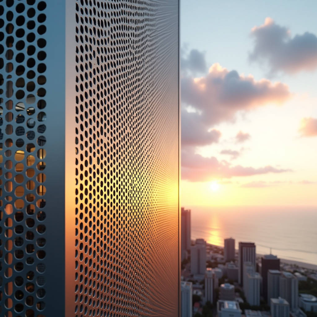
When a facade engineer specifies Aluminum Panel Perforation on a high-rise in a typhoon-prone coastal city, the first question is never about aesthetics. It is about structural survivability. A perforated solid aluminum panel with 35% open area behaves fundamentally differently under wind load than a solid sheet of the same thickness. The holes disrupt vortex shedding, reduce the net pressure coefficient, but simultaneously introduce stress concentrations around each perforation rim. Getting the specification right means balancing open area ratio, hole geometry, panel gauge, and the sub-frame design. This article walks through the structural mechanics, wind engineering considerations, and fabrication tolerances that determine whether a perforated aluminum facade will perform or fail over a 30-year service life.
Wind Load Behavior of Perforated Solid Aluminum Panels
Solid aluminum panels respond to wind as a continuous membrane. Once you introduce perforation, the panel transitions to a semi-porous element. Wind tunnel studies conducted under ASCE 7-22 protocols show that perforated cladding with open area ratios between 20% and 50% can experience a 15% to 40% reduction in net pressure coefficients compared to identical solid panels. This sounds like good news until you examine the localized effects.
The air passing through each hole creates micro-jet streams that impose fluctuating pressures on the interior edges of the perforation. These cyclical loads, though small in magnitude, accumulate millions of stress cycles over the building's life. For a 3.0mm thick 5052-H32 solid aluminum panel with 10mm diameter round holes at 15mm staggered centers, the stress concentration factor (Kt) around each hole typically ranges from 2.2 to 2.7 depending on edge distance from the nearest panel boundary. This means the material around the hole experiences nearly three times the nominal stress of the surrounding plate.
Engineers should not rely solely on the reduced overall wind load. The perforation pattern must be analyzed as a stress riser network. Finite element analysis (FEA) is the standard approach for panels with irregular hole patterns or high open area ratios exceeding 40%. For standard patterns, the Aluminum Association's ADM 2020 provides allowable stress design values that account for net section properties.
Open Area Ratio and Its Structural Trade-offs
Open area ratio, defined as the total area of perforations divided by the total panel area expressed as a percentage, is the single most consequential design parameter. Here is how it cascades through the structural system:
- 20% to 30% open area: The panel retains approximately 70% to 80% of its original bending stiffness. Standard aluminum sub-frame systems with mullion spacing up to 1,200mm can typically accommodate this range without reinforcement. Wind load reduction is modest at 10% to 20%.
- 30% to 40% open area: Bending stiffness drops to 50% to 65% of the solid panel. Sub-frame spacing often needs to be reduced to 900mm or less. The wind load reduction benefit becomes more meaningful at 20% to 30%.
- 40% to 50% open area: The panel begins behaving more like a mesh than a plate. Stiffness falls below 40% of original. Custom sub-frame engineering is almost always required. Wind load reduction can reach 35% to 40%, but the remaining load must be carried by a much weaker panel section.
- Above 50%: The panel is effectively a screen. It should be treated as a non-structural rain screen or decorative element. The sub-frame must carry all loads independently.
These are not linear relationships. The stiffness degradation accelerates past 35% open area because the remaining aluminum ligaments between holes approach their minimum width-to-thickness ratios. When the ligament width drops below 2.5 times the panel thickness, local buckling becomes the governing failure mode rather than gross yielding.
Material Selection for Perforated Applications
Not all aluminum alloys handle perforation equally. The punching or drilling process introduces cold work at the hole perimeter, which can alter the local temper condition. Alloy 5052-H32 is the industry benchmark for perforated architectural panels because it offers an excellent balance of formability, corrosion resistance, and post-perforation strength retention. The magnesium content (2.2% to 2.8%) provides solid solution strengthening that remains stable through the perforation process.
Alloy 3003-H14 is sometimes specified for interior applications or low-wind zones due to its lower cost. However, its yield strength of approximately 145 MPa compared to 5052-H32's 193 MPa means a 25% reduction in load-bearing capacity. For perforated panels, this difference is magnified because the net section is already reduced. A 3003-H14 panel with 35% open area may have an effective yield strength at the net section of only 94 MPa, which can be insufficient for exterior cladding in regions with design wind speeds exceeding 45 m/s.
Alloy 6061-T6 is occasionally used for perforated panels in high-traffic areas like canopies and walkway covers where impact resistance matters. The trade-off is that 6061-T6 has lower corrosion resistance in marine environments and is more prone to stress corrosion cracking at the perforation edges if not properly coated.
Coating Considerations for Perforated Panels
PVDF fluoropolymer coatings, typically applied at 25 to 35 microns dry film thickness for architectural aluminum, face a unique challenge on perforated panels: edge coverage. The interior walls of each perforation must be coated to prevent corrosion initiation. This is technically demanding because spray application tends to deposit thinner film on hole interiors than on the panel face.
For perforated panels specified for coastal or industrial environments, a two-coat PVDF system with a 5 to 8 micron primer and 20 to 25 micron color coat is the minimum acceptable standard. Three-coat systems with a 10 micron metallic base coat offer better edge coverage but at higher cost. Electrostatic application improves wrap-around onto hole interiors but still cannot guarantee full coverage on holes smaller than 6mm diameter.
Anodized finishes on perforated panels present a different set of issues. The anodizing process naturally coats the entire surface including hole interiors, which is an advantage. However, the anodic layer is brittle. When the panel flexes under wind load, micro-cracking can develop at the hole edges where stress concentrations are highest. For this reason, anodized perforated panels are generally limited to applications with design wind pressures below 1.5 kPa unless the hole pattern has been specifically engineered to maintain ligament flexibility.
| Coating System | Dry Film Thickness | Edge Coverage Quality | Recommended Environment | Relative Cost Index |
|---|---|---|---|---|
| 2-Coat PVDF (Primer + Color) | 25-30 μm | Moderate | Urban, Suburban | 1.0 |
| 3-Coat PVDF (Primer + Metallic + Clear) | 35-45 μm | Good | Coastal (within 5km) | 1.3-1.5 |
| 4-Coat PVDF (Primer + Barrier + Color + Clear) | 45-55 μm | Excellent | Industrial, Heavy Marine | 1.6-1.8 |
| Anodized (AA-M10C22A31, Class I) | 18-25 μm | Complete (process inherent) | Urban (limited flexure) | 0.8-1.0 |
| Polyester Powder (Qualicoat Class 1) | 60-80 μm | Moderate to Good | Interior, Sheltered Exterior | 0.7-0.9 |
Fabrication Tolerances and Quality Control
The precision of Aluminum Panel Perforation directly affects both structural performance and visual quality. Hole position tolerance is typically specified at ±0.25mm for CNC-punched panels and ±0.5mm for turret-punched production. These numbers matter because cumulative positional errors across a panel can create visible pattern distortion when panels are installed adjacent to each other. A 0.5mm error per hole over a 1,200mm wide panel with 15mm hole spacing means 80 holes per row, and a potential cumulative misalignment of up to 40mm at the far edge if errors are systematic rather than random.
Modern CNC punching centers with servo-driven axes can hold ±0.1mm positional accuracy, but this requires rigid tooling and proper sheet clamping. When panels exceed 2,400mm in length, the unsupported sheet can vibrate during punching, degrading accuracy. This is why high-end fabricators, including Futeng®, use intermediate support tables and vacuum hold-down systems for large-format perforated panels.
Hole diameter tolerance is equally critical. For 10mm round holes, the typical specification is +0.1mm/-0.0mm. Oversized holes reduce the net section area and increase the effective open area ratio beyond the design intent. Undersized holes are less structurally problematic but can cause aesthetic inconsistency. The punch tooling must be monitored for wear; carbide punches typically last 200,000 to 400,000 hits in 5052-H32 before diameter deviation exceeds 0.05mm.
Edge Distance and Pattern Layout Rules
The distance from the center of any perforation to the nearest panel edge should be at least 1.5 times the hole diameter, and preferably 2.0 times for panels in high-wind zones. This edge margin ensures that the aluminum ligament between the hole and the panel edge has sufficient shear capacity. For slotted perforations, the end radius of the slot governs the stress concentration, and the edge distance should be measured from the slot centerline.
Pattern layout must also account for the panel's bending and folding lines. Perforations should not intersect bend lines. The heat-affected zone from the perforation process, though minimal in cold-punched aluminum, can still create microstructural changes that affect bendability. A minimum 10mm unperforated margin along all bend lines is standard practice.
Acoustic Performance of Perforated Aluminum Facades
Perforated panels serve a dual role in many projects: they are both the aesthetic outer skin and a functional component of the building's acoustic strategy. The physics is straightforward. Sound waves passing through the perforations encounter viscous friction at the hole boundaries, converting acoustic energy into heat. The effectiveness depends on hole diameter, open area ratio, panel thickness, and the depth of the air cavity behind the panel.
For a typical perforated solid aluminum panel with 2.5mm thickness, 3mm hole diameter, and 25% open area, the sound absorption coefficient peaks around 0.65 to 0.75 at frequencies between 500 Hz and 1,000 Hz when backed by a 50mm air cavity with mineral wool insulation. This makes the configuration effective for speech-range noise control in office buildings and transportation terminals.
Smaller holes produce better acoustic performance at lower frequencies because the increased viscous resistance shifts the absorption peak downward. A panel with 1.5mm holes at 20% open area can achieve a sound absorption coefficient of 0.80 at 400 Hz with the same cavity depth. However, the smaller holes are more expensive to punch and more prone to clogging from airborne dust in urban environments.
The acoustic design should be coordinated with the structural design. Adding a perforated acoustic backing panel behind the outer perforated facade panel creates a double-perforated system that can achieve broadband absorption coefficients above 0.70 across the 250 Hz to 2,000 Hz range. The trade-off is additional weight, cost, and complexity in the sub-frame design.
Sub-Frame Engineering for Perforated Panel Systems
The sub-frame that supports perforated aluminum panels must address two conditions that solid panel sub-frames do not: reduced panel stiffness and the need for uninterrupted airflow behind the panel. Standard aluminum extrusion sub-frames with 50mm to 100mm depth are typically adequate, but the attachment point spacing must be recalculated based on the perforated panel's reduced section modulus.
For a 2.5mm thick solid aluminum panel, the section modulus per meter width is approximately 1,042 mm³/m. With 35% open area from a staggered round hole pattern, the effective section modulus drops to roughly 620 mm³/m. This means the sub-frame attachment points must be spaced 25% to 30% closer than they would be for an equivalent solid panel to maintain the same deflection limit of L/175 under design wind load.
The sub-frame must also resist the torsional loads that arise when wind passes through the perforations at an oblique angle. These loads are small individually but can excite vibration modes in the panel if the natural frequency of the panel-sub-frame assembly falls within the vortex shedding frequency range. A general rule is to keep the panel's first natural frequency above 5 Hz for buildings under 100 meters and above 3 Hz for taller structures where wind turbulence is more broadband.
Corrosion Protection at Attachment Points
The interface between the aluminum panel and the sub-frame is a corrosion risk zone. Galvanic corrosion can occur if the sub-frame is made of steel or if stainless steel fasteners are used without isolation. For perforated panels, the risk is elevated because moisture can reach the attachment points from both the front (through the perforations) and the rear of the panel.
Best practice calls for EPDM or neoprene isolation gaskets between the panel and sub-frame at every attachment point. Fasteners should be 316-grade stainless steel with nylon or EPDM washers. The panel's perforation pattern should be designed so that no hole aligns directly with an attachment point, as this creates a direct moisture path to the fastener head.
Cost Drivers in Perforated Aluminum Panel Projects
Perforation adds cost to aluminum panels through several mechanisms. The punching operation itself is the most obvious: CNC punching time scales with the number of holes, not the open area ratio. A panel with 5,000 small holes costs more to punch than one with 500 large holes, even if both have the same open area ratio. The scrap rate is also higher for perforated panels because any hole pattern error renders the entire panel unusable.
The material yield loss from perforation is another factor. The aluminum punched out of the holes is typically recycled, but the recovery value is only 30% to 50% of the original sheet cost. For a panel with 40% open area, this represents a significant material cost that cannot be fully recovered.
Finishing costs are also higher for perforated panels. The coating process must achieve adequate coverage on hole interiors, which often requires slower line speeds, multiple passes, or manual touch-up. Quality inspection is more labor-intensive because every hole edge must be checked for coating continuity.
Despite these costs, perforated aluminum panels can reduce overall project costs by eliminating the need for separate sunshades, acoustic treatments, or ventilation louvers. When the panel serves multiple functions, the integrated solution is often cheaper than layering separate systems. A reputable manufacturer like Futeng® can provide detailed cost-benefit analyses that account for these system-level savings.
Installation Sequencing and Site Handling
Perforated panels are more susceptible to handling damage than solid panels. The aluminum ligaments between holes can bend or tear if the panel is lifted improperly. Suction cup lifters that work perfectly on solid panels can fail on perforated panels because the cups cannot maintain vacuum over the holes. Spreader bars with padded clamps that grip the panel edges are the recommended lifting method.
On-site cutting of perforated panels should be avoided whenever possible. Field-cut edges rarely match the factory edge quality, and the cut edge will lack the factory-applied coating. If field modification is unavoidable, the cut edge must be dressed with a file to remove burrs and then treated with a cold-applied PVDF touch-up coating. The touch-up will never match the factory finish perfectly, so cut edges should be located in concealed areas.
Panel installation sequence should account for the directional appearance of the perforation pattern. Many patterns look different when viewed from above versus below, or from left versus right. The installation drawings must clearly indicate the orientation of each panel. This is especially important for slotted or custom-shaped perforations where the pattern has an obvious grain direction.
Long-Term Performance and Maintenance
Perforated aluminum panels in exterior applications accumulate dirt, salt, and pollutants differently than solid panels. The hole edges trap particulate matter, and the airflow through the panel can deposit contaminants on the rear surface and the sub-frame. In coastal environments, salt spray passing through the perforations can accelerate corrosion of sub-frame components if they are not adequately protected.
Cleaning perforated panels requires more care than solid panels. Pressure washing can drive water into the cavity behind the panel, potentially damaging insulation or interior finishes. Low-pressure washing with a fan nozzle at a minimum 45-degree angle to the panel face is the safest approach. The cleaning frequency should be specified in the project's maintenance manual; for urban environments, annual cleaning is typical, while coastal locations may require semi-annual cleaning.
Inspection protocols should include checking for cracks radiating from perforation holes, particularly at panel corners where stress concentrations are highest. A borescope can be used to inspect the condition of the sub-frame and attachment points through the perforations without removing panels. Any panel showing cracks at more than 5% of its perforation holes should be scheduled for replacement.
The engineering of Aluminum Panel Perforation for structural facades requires a multidisciplinary approach that integrates wind engineering, material science, fabrication technology, and installation logistics. The perforation pattern is not merely a design motif; it is a structural modification that fundamentally alters how the panel interacts with wind, sound, and the surrounding building systems. Getting the specification right from the outset, with proper attention to alloy selection, coating system, sub-frame design, and quality control tolerances, determines whether the facade will perform reliably for decades or become a maintenance liability. For project teams navigating these decisions, working with manufacturers who have deep experience in both standard and custom perforation programs can significantly reduce the technical risk.