Plasma Cutting Aluminum Panel Edge Quality and Coating Adhesion for Architectural Cladding
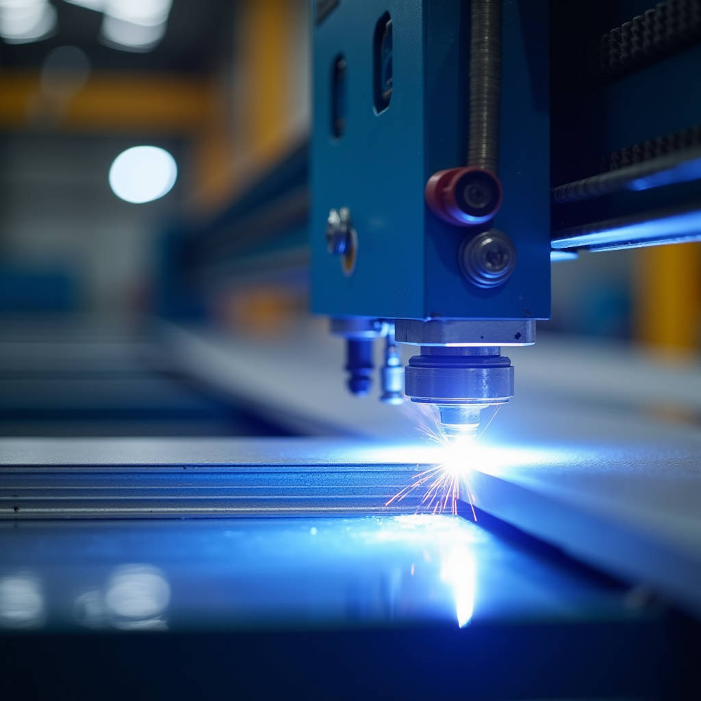
Plasma cutting aluminum panel fabrication has become a non-negotiable capability for facade contractors handling large-scale architectural cladding projects. When a specification calls for 2.5mm solid aluminum panels with intricate perforation patterns, irregular perimeter geometries, or on-site modification requirements, the difference between a shop that understands plasma cutting and one that defaults to shearing or routing can mean thousands of dollars in rework costs. This article examines the specific intersection of plasma cutting technology and solid aluminum cladding panel production — focusing on edge quality thresholds that satisfy AAMA 2605 coating adhesion requirements, the gas selection logic that prevents oxide contamination on PVDF-finished surfaces, and the production workflow decisions that separate profitable facade contracts from margin-eroding disasters.
Why Solid Aluminum Panels Demand a Different Plasma Approach
Solid aluminum cladding panels — typically 2.0mm, 2.5mm, or 3.0mm thick 1100-H14, 3003-H14, or 5052-H32 alloy sheets — present a fundamentally different cutting challenge than the mild steel most plasma operators are trained on. Aluminum's thermal conductivity is roughly five times higher than carbon steel. Heat dissipates through the workpiece almost instantly, which means the arc must deliver concentrated energy faster than the material can wick it away. A plasma cutter dialed in for 10-gauge steel will produce a ragged, dross-heavy edge on 2.5mm aluminum because the operator never compensated for thermal bleed.
The stakes are higher for architectural panels. A rough plasma cut on a structural bracket might be acceptable after grinding. A rough cut on the visible face of a rainscreen panel — or worse, on the folded return edge that will receive a silicone sealant joint — is a rejection waiting to happen. The edge must be clean enough to accept PVDF or FEVE fluoropolymer coating without fisheyes, pinholes, or adhesion failures at the cut line. This is not a theoretical concern: coating manufacturers require surface profiles of 25-50 microns (1-2 mils) for optimal mechanical adhesion. A plasma cut with excessive oxidation or edge rounding can create a surface that coating simply will not bond to reliably.
Gas Selection: The Decision That Shapes Edge Quality
The single most consequential variable in plasma cutting aluminum panel stock is gas selection. Aluminum forms a tenacious aluminum oxide layer that melts at approximately 2,070°C — nearly three times higher than the aluminum substrate underneath. When plasma cutting with compressed air alone, the oxygen content in the air stream accelerates oxide formation at the cut face, producing a thick, blackened edge that must be mechanically removed before coating. For architectural panels destined for PVDF finishing, this is unacceptable.
Three gas configurations dominate production environments:
| Gas Configuration | Edge Appearance | Post-Cut Prep Required | Relative Cost | Best Application |
|---|---|---|---|---|
| Compressed Air / Air | Dark gray to black oxide layer, moderate dross | Heavy grinding or sanding | Lowest | Non-visible structural brackets, temporary jigs |
| Argon-Hydrogen (65/35) / Nitrogen Shield | Bright, nearly oxide-free silver edge | Minimal — light deburring only | Highest | PVDF-coated architectural panels, visible edges |
| Nitrogen / Nitrogen | Light gray, minimal oxide | Light sanding | Moderate | FEVE-coated panels, interior cladding |
| Compressed Air / Water Mist | Medium gray, reduced dross | Moderate sanding | Low-Moderate | Shop-cut blanks prior to folding and coating |
Argon-hydrogen mixtures deliver the cleanest edge because the hydrogen acts as a reducing agent, stripping oxygen from the cut zone. The nitrogen shield gas further isolates the molten aluminum from atmospheric contamination. For a facade contractor cutting 500 panels per project, the added gas cost — typically $0.80-$1.20 per linear meter of cut — is negligible compared to the labor savings from eliminating post-cut edge preparation. Shops that insist on running compressed air through aluminum panel stock inevitably spend more on grinding labor than they save on gas.
Amperage, Speed, and the Dross Sweet Spot
Aluminum plasma cutting produces two distinct dross types, and understanding which one you are dealing with determines whether you adjust amperage or travel speed. High-speed dross forms when the arc moves too fast for the material thickness — the plasma jet does not fully penetrate the bottom of the kerf, and a hard, tightly bonded deposit forms along the bottom edge. This dross is difficult to remove and often requires chipping or heavy grinding. Low-speed dross forms when travel speed is too slow — the arc over-penetrates, and molten material pools and re-solidifies as a soft, easily removable deposit. The latter is far preferable for architectural panels, as a quick pass with a deburring tool clears it without damaging the edge profile.
For 2.5mm solid aluminum panels, production data from multiple fabrication shops indicates the following starting parameters on a 65-amp mechanized plasma system:
- Amperage: 45-55 amps (not the full 65 amps — aluminum requires less current than steel of equivalent thickness)
- Travel speed: 2,800-3,500 mm/min (110-140 inches/min) on argon-hydrogen; 2,200-2,800 mm/min (85-110 inches/min) on compressed air
- Standoff distance: 1.5-2.0mm (0.060-0.080 inches) — tighter than steel cutting to maintain arc constriction
- Kerf width: Expect 1.5-2.0mm (0.060-0.080 inches), which must be factored into nesting calculations
These numbers are starting points. Aluminum alloy, ambient humidity, torch consumable age, and even the specific panel thickness tolerance (a nominally 2.5mm panel may measure 2.35-2.65mm depending on mill source) will shift the optimal parameters. Production managers who treat these settings as fixed rather than as baselines for test-cut validation will generate scrap panels.
Distortion Control: When Heat Input Becomes a Panel Rejection
Flatness is non-negotiable in architectural cladding. A 2.5mm solid aluminum panel with even 3mm of bow across a 1,200mm span will telegraph through the rainscreen system, creating visible waves that catch glancing light and trigger a site rejection. Plasma cutting introduces concentrated heat along the cut path, and aluminum's high thermal expansion coefficient (roughly 23.6 × 10⁻⁶ /°C for 3003 alloy) means that heat translates directly into dimensional movement.
Three strategies mitigate plasma-induced distortion on aluminum panels:
- Staggered cutting sequences: Rather than cutting perimeter geometry in one continuous pass, experienced operators program the CNC to cut alternating segments, allowing the panel to cool between passes. This is particularly critical for panels with large internal cutouts — cutting the internal feature first, then the perimeter, prevents the panel from warping when the center material drops free.
- Water table cutting: Submerged or water-table plasma cutting absorbs radiant heat and captures aluminum oxide dust simultaneously. The water acts as a heat sink, dramatically reducing the heat-affected zone width. Panels cut on a water table typically exhibit 40-60% less distortion than those cut on a dry table, though the trade-off is slightly reduced cut speed and the need for post-cut drying before coating.
- Tab-and-break techniques: For panels with complex internal geometries, leaving small uncut tabs (0.5-1.0mm) at strategic points prevents the cutout from shifting during the cutting process. These tabs are broken and cleaned during secondary finishing. This approach adds labor but eliminates the risk of a shifted cutout scrapping an otherwise finished panel.
Perforated Panel Plasma Cutting: Managing the Cumulative Heat Load
Architectural perforated panels — increasingly specified for solar shading, acoustic attenuation, and decorative facade screens — represent the most demanding plasma cutting application in cladding fabrication. A single 1,200mm × 2,400mm panel may contain 800-2,000 individual perforations. Each plasma pierce introduces a localized heat spike, and the cumulative thermal load can warp a panel beyond flatness tolerance before the cutting program reaches 50% completion.
The solution lies in the pierce sequence, not the plasma parameters. Random-path piercing algorithms, where the CNC controller distributes pierce locations across the panel rather than proceeding row-by-row, allow each pierce site to cool before adjacent material is heated. Some advanced nesting software includes thermal modeling that predicts cumulative heat input and automatically adjusts pierce sequencing. For shops without this capability, a manual approach works: divide the panel into quadrants, pierce one hole per quadrant in rotation, and only return to quadrant one after all four quadrants have received one pierce each.
Perforation diameter also matters. Plasma-cut holes below 3mm diameter on 2.5mm aluminum tend to produce inconsistent geometry because the arc cannot fully constrict within such a small kerf. For perforations smaller than 3mm, punching or laser cutting is generally superior. Between 3mm and 12mm, plasma with argon-hydrogen provides excellent hole quality. Above 12mm, plasma is the most cost-effective method by a significant margin.
Coating Adhesion: The Edge Quality Standard That Matters
A PVDF architectural coating system — typically a three-coat (primer, color, clear) or four-coat (primer, barrier, color, clear) system applied at 35-45 microns total dry film thickness — demands a specific surface condition at every cut edge. The AAMA 2605 standard, which governs high-performance organic coatings on aluminum extrusions and panels, requires that coated panels pass 4,000+ hours of accelerated weathering without adhesion loss, blistering, or edge creep exceeding 1/16 inch (1.6mm).
Plasma-cut edges that have not been properly prepared will fail edge creep testing. The failure mechanism is straightforward: the aluminum oxide layer formed during plasma cutting is chemically stable but mechanically weak. Coating applied over this oxide layer adheres to the oxide, not the aluminum substrate. When moisture penetrates the coating-oxide interface during weathering, the oxide layer delaminates from the aluminum, and the coating creeps backward from the edge.
The fix is not complicated but must be systematic. After plasma cutting, every edge that will receive coating must be mechanically abraded — typically with 120-180 grit aluminum oxide abrasive — to remove the plasma-formed oxide and expose fresh aluminum. The window between abrasion and coating application should not exceed 4 hours in uncontrolled humidity environments, as aluminum begins re-oxidizing immediately. Shops that batch-cut panels on Monday and send them to coating on Friday are setting themselves up for adhesion failures that may not manifest until the panels have been on the wall for 18 months.
Futeng® has documented this workflow extensively in their architectural panel fabrication guidelines, emphasizing that the cost of edge preparation is approximately $0.15-$0.25 per linear meter — a trivial expense compared to the cost of replacing failed panels on an occupied building.
CNC Plasma vs. Handheld: When Portability Beats Precision
Not every plasma cut on an aluminum cladding panel happens in a controlled shop environment. Field modifications — adjusting a panel to accommodate an as-built deviation, cutting a penetration for a late-added conduit, or trimming a perimeter panel to fit an unexpected site condition — require handheld plasma cutting. The quality ceiling for handheld cutting is lower than CNC, but competent operators can produce field cuts that are functionally acceptable, if not aesthetically identical to shop cuts.
The critical handheld technique for aluminum panels is maintaining consistent standoff distance. Without the mechanical standoff control of a CNC gantry, the operator must visually track the nozzle-to-workpiece gap. A drag shield or roller guide attachment is essential — freehand cutting without standoff control will produce wildly variable edge quality and likely gouge the panel surface. Second, handheld cutting should always use a straightedge guide for linear cuts. The temptation to cut freehand along a marked line is strong, but the resulting edge waviness will be visible once the panel is installed, particularly on joints with narrow (10-12mm) open gaps where there is no trim or cover strip to hide irregularities.
For field cuts on PVDF-coated panels, the heat-affected zone will extend 2-3mm beyond the cut line, discoloring the coating. This must be accounted for in the cut layout — position the cut line so that the heat-affected zone falls within the joint gap or behind a cover flashing, not on visible panel surface.
Production Economics: Plasma Cutting Cost per Linear Meter
Fabrication estimators need hard numbers. The fully burdened cost of plasma cutting aluminum panels — including consumables, gas, electricity, labor, and equipment amortization — breaks down as follows for a mid-volume shop running one 8-hour shift:
| Cost Component | Per Linear Meter (2.5mm Al, Ar-H2) | Per Linear Meter (2.5mm Al, Compressed Air) | Notes |
|---|---|---|---|
| Consumables (electrode, nozzle, shield) | $0.18 - $0.25 | $0.22 - $0.30 | Air cutting accelerates electrode wear on aluminum |
| Gas (plasma + shield) | $0.80 - $1.20 | $0.05 - $0.10 | Ar-H2 is the dominant cost driver |
| Electricity | $0.04 - $0.06 | $0.04 - $0.06 | Negligible at typical industrial rates |
| Labor (operator + overhead) | $0.50 - $0.75 | $0.50 - $0.75 | Assumes CNC operation; handheld labor is 2-3× higher |
| Equipment amortization | $0.30 - $0.50 | $0.30 - $0.50 | Based on $45K system, 5-year life, 2,000 hrs/year |
| Post-cut edge prep (grinding/sanding) | $0.15 - $0.25 | $0.40 - $0.70 | Air-cut edges require significantly more prep |
| Total per linear meter | $1.97 - $3.01 | $1.51 - $2.41 | Air appears cheaper until edge prep is fully accounted |
The counterintuitive finding: argon-hydrogen cutting, despite its higher gas cost, produces a lower total cost per usable linear meter when edge preparation for coating is included. The $0.25-$0.45 savings in edge prep labor more than offsets the $0.75-$1.10 additional gas cost. Shops that optimize for gas cost alone are optimizing the wrong variable.
Aluminum-Specific Consumable Wear Patterns
Plasma cutting aluminum accelerates electrode wear through a mechanism that differs from steel cutting. Aluminum's low melting point means that microscopic aluminum particles can spatter back onto the electrode surface during piercing, creating a hafnium-aluminum intermetallic that erodes the hafnium insert faster than the pure hafnium erosion seen in steel cutting. Electrode life when cutting aluminum is typically 60-70% of the life achieved on steel at equivalent amperage.
Operators should inspect electrodes after every 150-200 pierces on aluminum panel stock. The failure mode is not dramatic — electrode erosion gradually widens the arc, increasing kerf width and reducing edge squareness. By the time the operator notices degraded cut quality, the electrode has been underperforming for dozens of cuts. A disciplined consumable replacement schedule, tracked by pierce count rather than visual inspection, produces more consistent panel quality than a reactive approach.
Nozzle selection also matters. Standard nozzles designed for steel cutting produce acceptable results on aluminum, but nozzles with a slightly larger orifice diameter (by 0.1-0.2mm) and reduced swirl can reduce dross formation on aluminum by allowing a slightly softer, less constricted arc. This is a subtle optimization that most shops discover through trial and error rather than documentation.
Integrating Plasma Cutting into the Panel Fabrication Workflow
The sequence of operations in a cladding panel fabrication shop determines whether plasma cutting is a bottleneck or a value-adding process. The optimal workflow for solid aluminum panels destined for architectural installation is:
- Sheet inspection and flatness verification: Accept or reject incoming aluminum sheet stock before cutting begins. A panel that enters the workflow with 2mm of bow will exit with more.
- Plasma cutting (CNC): Cut perimeter geometry, internal cutouts, and perforations in a single setup where possible. Staggered cutting sequence to manage heat input.
- Edge preparation: Mechanical abrasion of all cut edges within the coating preparation window. Remove dross, oxide layer, and any surface contaminants.
- Forming (bending, folding, routing): Plasma-cut blanks proceed to CNC folding. The cut edge quality directly affects bend accuracy — a ragged edge can cause inconsistent bend lines.
- Surface preparation and coating: Chromate conversion coating or alternative pretreatment, followed by PVDF or FEVE liquid coating application.
- Final inspection: Check flatness, coating adhesion, edge quality, and dimensional accuracy against project specifications.
Shops that insert plasma cutting after forming — for example, cutting a penetration in an already-folded panel — are working against themselves. The formed panel is harder to fixture, the plasma torch must navigate around returns and stiffeners, and the risk of heat distortion on a panel that has already been brought to final shape is significantly higher.
Quality Verification: What to Measure Before Coating
Between plasma cutting and coating, every panel edge should be subjected to a quick but systematic quality check. The minimum verification includes:
- Edge squareness: The cut face should be within 3° of perpendicular to the panel surface. Excessive bevel creates a thin feathered edge that coating cannot adequately cover.
- Dross removal: No visible dross deposits remaining on the bottom edge. A fingernail dragged along the edge should not catch on any protrusion.
- Surface roughness: The cut edge should have a surface roughness (Ra) of 6.3-12.5 microns (250-500 microinches) after abrasion — coarse enough for mechanical coating adhesion but not so rough that coating thickness at the edge is compromised.
- Oxide removal: The edge should appear bright silver, not gray or black. A simple water-break test — water applied to the edge should form a continuous sheet, not bead up — confirms that the oxide layer has been removed and the surface is chemically active for coating adhesion.
These checks add approximately 30-45 seconds per panel and catch problems that coating line operators may not see until panels emerge from the cure oven, at which point the cost of rework is dramatically higher.
The American Architectural Manufacturers Association (AAMA) provides detailed surface preparation standards in AAMA 2605 that apply directly to plasma-cut edges on architectural aluminum. Similarly, ISO 12944 on corrosion protection and ASTM B209 for aluminum sheet specifications establish the material and finishing framework within which plasma cutting must operate. The Aluminum Association also publishes alloy-specific data sheets that inform cutting parameter selection.
Making Plasma Cutting Work for Architectural Aluminum
Plasma cutting aluminum panel stock is not inherently difficult, but it is unforgiving of shortcuts. The shops that produce consistently high-quality architectural panels — panels that arrive on site flat, with clean edges that accept coating without adhesion failures — are the shops that treat gas selection, consumable management, and edge preparation as interconnected processes rather than isolated tasks. The argon-hydrogen investment pays for itself in reduced rework. The staggered cutting sequence prevents the flatness issues that plague rushed production. The systematic edge preparation ensures that AAMA 2605 compliance is achieved on every panel, not just the ones that happen to be cut on a good day.
For project managers and procurement teams specifying solid aluminum cladding, the takeaway is straightforward: ask your fabricator about their plasma cutting gas configuration and edge preparation protocol. If they cannot answer in detail, they are probably not producing panels that will perform over a 30-year building lifecycle. The difference between a panel that looks good on installation day and one that still looks good after two decades of UV exposure, thermal cycling, and moisture is often determined in the 30 seconds that panel spent under a plasma torch.