Laser Cutting Aluminum Panel Wind Load Performance and Perforation Engineering for Solid Facade Cladding
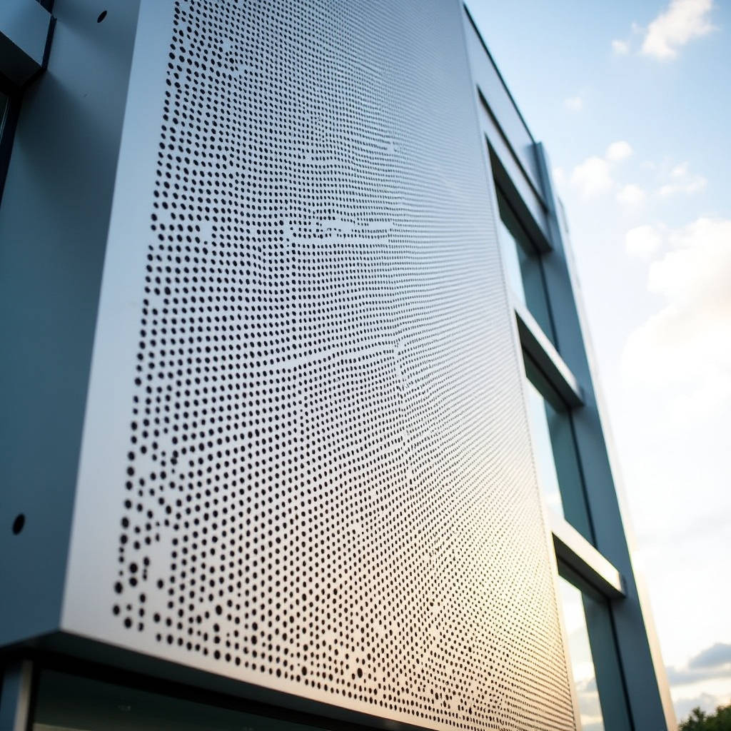
Laser cutting aluminum panel technology has reshaped what architects and facade engineers can achieve with solid aluminum cladding. A laser-cut aluminum panel delivers edge geometry that traditional punching or routing simply cannot match — kerf widths down to 0.15 mm, taper angles under 1°, and the ability to produce intricate perforation patterns without inducing micro-cracks along the cut path. For building envelope professionals, the conversation extends beyond aesthetics. The real question is how laser-cut perforations affect structural performance, particularly wind load resistance, when you remove material from a 2.5 mm or 3.0 mm solid aluminum sheet. This article examines the intersection of perforation ratio, panel stiffness, and code compliance — a topic that rarely gets the depth it deserves in technical specifications.
How Perforation Ratio Affects the Structural Capacity of a Laser Cutting Aluminum Panel
Every hole cut into a solid aluminum panel reduces the effective cross-sectional area that resists bending. A panel with 30% open area does not simply lose 30% of its stiffness — the relationship is nonlinear and depends heavily on pattern geometry. For a simply supported rectangular panel under uniform wind load, the maximum deflection follows a modified plate theory where the effective flexural rigidity Deff drops faster than the solid-area ratio would suggest.
Consider a 2.5 mm thick 5052-H32 aluminum panel measuring 1200 mm × 2400 mm. In its solid state, with a typical 50 MPa yield strength, the panel can span approximately 600 mm between stiffeners at a design wind pressure of 1.5 kPa. Introduce a staggered round-hole perforation pattern at 25% open area, and the effective bending stiffness drops to roughly 55-60% of the original value — not 75% as a linear assumption would predict. This happens because the perforations create stress concentration points where localized yielding initiates earlier than in a continuous sheet.
The mechanism matters. When a laser cutting aluminum panel undergoes perforation, the heat-affected zone (HAZ) around each cut is minimal — typically 0.05-0.10 mm with modern fiber lasers — but the geometric discontinuity remains. Stress flows around holes like water around bridge piers, concentrating at the hole boundaries. For circular holes in a triangular pitch pattern, the stress concentration factor Kt ranges from 2.2 to 2.8 depending on the pitch-to-diameter ratio. Engineers who ignore this and apply simple area-reduction factors are designing panels that may deflect 40-60% more than calculated under service loads.
Pattern Geometry: Staggered vs. Grid Arrangements Under Wind Load
Not all perforation patterns behave equally. A staggered (60° triangular pitch) arrangement distributes stress more evenly than a square grid pattern at the same open-area ratio. Testing data from aluminum sheet manufacturers shows that staggered patterns retain approximately 8-12% more effective stiffness compared to inline square patterns. The reason lies in the ligament efficiency — the continuous metal paths between holes are longer and more tortuous in staggered layouts, forcing stress to travel a longer path and reducing peak concentrations.
For a laser cutting aluminum panel destined for a high-rise facade where wind pressures can reach 3.0-4.0 kPa at corner zones, pattern selection becomes a compliance issue. ASTM E330 testing on perforated panels with 35% open area in staggered configuration has demonstrated ultimate load capacities of 2.8-3.2 kPa before exceeding L/60 deflection limits. The same panel with a square grid pattern at identical open area typically fails the same deflection criterion at 2.2-2.6 kPa — a difference that can determine whether a panel passes or fails a project's specified performance requirements.
Alloy Selection for Perforated Facade Panels: Why 5052 and 5754 Dominate
Aluminum alloy choice dictates how a laser-cut panel behaves during fabrication and throughout its service life. The 5000 series — specifically 5052-H32 and 5754-H22 — has become the default for perforated architectural cladding, and for good engineering reasons that go beyond corrosion resistance.
5052-H32 offers a yield strength of approximately 193 MPa with elongation around 12-18%. This combination provides enough strength for spanning between sub-frame members while retaining sufficient ductility to prevent brittle fracture at perforation edges. More critically, 5052 work-hardens at a moderate rate, meaning the laser-cut edges do not become excessively hardened or susceptible to stress-corrosion cracking — a documented failure mode in 6000-series alloys when perforated and exposed to coastal environments.
5754-H22, with slightly lower yield strength (around 185 MPa) but higher elongation (15-20%), performs better when the design calls for deep perforation patterns with narrow ligaments. The additional ductility allows the remaining metal between holes to redistribute stress through local plastic deformation before crack initiation. For projects within 5 km of marine coastlines, 5754 also offers marginally better resistance to pitting corrosion due to its lower magnesium content (2.6-3.6% vs. 5052's 2.2-2.8%) and controlled iron-to-manganese ratio.
3003-H14 occasionally appears in specifications for interior decorative screens, but its lower yield strength (approximately 145 MPa) means thicker gauges are required to achieve the same span ratings — typically 3.0 mm where 5052 would use 2.5 mm, adding weight and cost that often negates the raw material price advantage.
| Alloy & Temper | Yield Strength (MPa) | Elongation (%) | Corrosion Resistance | Recommended Max. Open Area | Typical Gauge for Facade |
|---|---|---|---|---|---|
| 5052-H32 | 193 | 12-18 | Excellent (general) | 40% | 2.0-3.0 mm |
| 5754-H22 | 185 | 15-20 | Excellent (coastal) | 45% | 2.0-3.0 mm |
| 3003-H14 | 145 | 8-16 | Good (interior) | 30% | 2.5-3.5 mm |
| 6061-T6 | 276 | 8-10 | Moderate (stress cracking risk) | 25% | 2.0-2.5 mm |
| 5005-H14 | 165 | 8-14 | Excellent | 35% | 2.0-3.0 mm |
Heat-Affected Zone and Edge Quality: What Fiber Lasers Deliver
The HAZ in laser cutting aluminum panel processing is substantially narrower than what plasma or even waterjet cutting produces in terms of metallurgical alteration. A 3 kW fiber laser cutting 2.5 mm 5052 at 18 m/min produces a HAZ depth of approximately 0.05-0.08 mm — essentially negligible for structural purposes. The kerf width sits at 0.15-0.20 mm, enabling pattern features with internal radii as tight as 0.5 mm without compromising edge quality.
Edge quality directly affects coating adhesion. A laser-cut edge on aluminum exhibits a slight surface roughness (Ra 3.2-6.3 μm) that actually improves mechanical bonding for subsequent PVDF or polyester powder coating. This is a critical detail: edges that are too smooth (as from fine blanking) can cause coating delamination at the hole perimeter, while edges that are too rough (as from abrasive waterjet) create stress risers and coating thin spots. The laser-cut edge sits in the optimal range for pretreatment chemicals to penetrate and for primer to anchor mechanically.
Oxide formation along the cut edge deserves attention. Fiber lasers operating with nitrogen assist gas produce clean, oxide-free edges that require no secondary cleaning before chromate conversion coating. Oxygen-assisted cutting, while faster, leaves a thin aluminum oxide layer that can interfere with pretreatment chemical bonding. For architectural panels where edge corrosion resistance matters — particularly in perforated designs where every hole edge is exposed — nitrogen assist gas adds approximately 10-15% to cutting cost but eliminates a significant long-term failure risk.
Wind Load Calculations for Perforated Panels: Beyond the Simple Area Method
ASCE 7 and EN 1991-1-4 provide wind load calculation frameworks, but neither standard directly addresses perforated cladding panels. The common engineering shortcut — multiplying the design wind pressure by the solidity ratio — is conservative for some failure modes and unconscionably optimistic for others.
For a laser cutting aluminum panel with 30% open area, the net pressure on the solid portions does not simply reduce by 30%. Wind tunnel studies on perforated facade screens indicate that the pressure coefficient Cp on a perforated panel can actually increase at certain porosity ratios because the openings allow partial pressure equalization that creates complex internal flow patterns. At 20-30% porosity, the net pressure coefficient can be 10-15% higher than the solid-panel equivalent for the same building geometry.
The more reliable approach treats the perforated panel as a porous screen and applies the methodology outlined in ASCE 7-16 Section 29.4 for open signs and lattice frameworks. The force coefficient Cf is calculated as:
Cf = Cf,solid × (1 - ε)1.5 where ε is the porosity ratio (0.3 for 30% open area).
This exponent of 1.5 — rather than a linear 1.0 — accounts for the three-dimensional flow effects through the panel. For a panel at 30% porosity, the effective force coefficient becomes approximately 0.59 times the solid panel value, not 0.70. The difference translates to approximately 16% lower wind force, which can be the margin that keeps a panel within deflection limits without adding stiffeners.
Futeng® engineers have applied this methodology across multiple high-rise projects where perforated solid aluminum panels required compliance with both ASTM E330 structural testing and AAMA 508 fatigue testing for curtain wall components. The key is documenting the calculation methodology in the project-specific performance mock-up report so that the building official has a clear load path from design wind speed to panel attachment.
Attachment Design: Why Fastener Spacing Changes with Perforation
Perforated panels concentrate stress not only around individual holes but also around attachment points. A panel with 35% open area that uses the same fastener spacing as a solid panel of identical thickness is likely to exhibit tear-out failures at the fasteners before the panel itself reaches its design capacity.
The fix is straightforward: reduce fastener spacing or increase the edge distance from the fastener centerline to the panel edge. For solid panels, a 25 mm edge distance is standard. For perforated panels above 25% open area, increasing this to 35-40 mm provides a larger shear area in the aluminum to resist pull-through and tear-out. The additional material at the perimeter also helps distribute concentrated loads from wind suction into the panel body without overloading the ligaments between perforations near the edges.
Coating Systems for Perforated Panels: The Edge Coverage Problem
PVDF coil-coated aluminum sheets are the industry standard for solid facade panels, but laser cutting aluminum panel fabrication introduces a complication: the cut edges expose bare aluminum that the coil-coating process never covered. On a solid panel, only the perimeter edges are exposed. On a panel with thousands of laser-cut perforations, the total exposed edge length can exceed 50 linear meters per square meter of panel surface — a massive potential corrosion initiation zone.
Three approaches address this:
- Post-cut coating: The panel is cut from pre-coated coil, then the entire panel — edges and all — receives a liquid PVDF spray coating. This provides continuous film coverage across all cut edges. The challenge is achieving uniform film thickness inside small-diameter holes without bridging or clogging.
- Pre-cut coating: The aluminum sheet is laser-cut in the mill finish state, then the entire perforated panel goes through pretreatment and coating. This ensures edge coverage but requires careful handling to prevent distortion of the perforated sheet during the coating line's tensioning process.
- Anodizing after cutting: For projects where metallic appearance is desired, the panel can be laser-cut in mill finish and then anodized. The anodic oxide layer grows on all exposed surfaces including hole interiors. The limitation is that anodizing offers less color consistency than PVDF and is generally limited to 20-25 μm film thickness versus PVDF's 30-40 μm.
For coastal projects, option 2 — pre-cut coating — combined with 5754 alloy and a chromate conversion pretreatment conforming to ASTM B449 Class 1A, provides the most robust corrosion protection system. The incremental cost over standard coil-coating is approximately 15-20%, but the alternative — edge corrosion appearing within 3-5 years on a 30-story building — is not a risk worth taking.
Thermal Movement and Perforation: A Frequently Overlooked Interaction
Aluminum expands at approximately 23.4 × 10⁻⁶ per °C. A 3-meter panel subjected to a 60°C temperature swing (from -10°C winter night to 50°C summer solar gain) will expand by about 4.2 mm. In a solid panel, this expansion is uniform and accommodated by the attachment system's slotted holes or sliding clips.
In a laser cutting aluminum panel with extensive perforation, thermal expansion becomes non-uniform. The solid perimeter frame expands as a continuous member, while the perforated field — with its reduced cross-section and higher surface-area-to-volume ratio — heats and cools at a different rate. Differential expansion between the panel field and its edges can induce buckling if the panel is restrained too rigidly.
The practical solution involves two design adjustments. First, the attachment system should allow movement not only at the panel perimeter but also accommodate slight in-plane rotation. Second, for panels exceeding 2.4 meters in any dimension with open areas above 30%, a ribbed or hat-section stiffener bonded to the rear face can maintain flatness during thermal cycling. The stiffener should be attached with structural adhesive (typically a two-part epoxy or modified silane) rather than mechanical fasteners, which would create additional stress concentration points in an already perforated sheet.
Cost Drivers: What Actually Determines the Price of a Laser Cutting Aluminum Panel
Procurement managers evaluating laser-cut aluminum cladding tend to focus on the per-square-meter price, but the real cost drivers are more nuanced. The three factors that most significantly affect the final installed cost are:
Cutting time per panel: Fiber laser cutting speed for 2.5 mm 5052 aluminum runs approximately 15-22 meters per minute with a 3 kW source. A panel with 1,500 perforations of 8 mm diameter requires roughly 37.7 meters of linear cutting. At 18 m/min, that is about 2.1 minutes of pure cutting time. Add rapid traverse movements between holes, and the cycle time per panel approaches 3.5-4.0 minutes. Doubling the hole count to 3,000 nearly doubles the cycle time — and the machine cost allocation.
Nesting efficiency: A 1500 mm × 3000 mm sheet can yield different panel quantities depending on the panel dimensions. Rectangular panels nest efficiently; irregular shapes with large solid borders waste material. Sheet utilization below 75% drives the effective material cost per panel up by 30% or more compared to 90% utilization.
Secondary operations: Deburring is generally unnecessary with properly tuned laser parameters, but panel flattening after cutting may be required if residual stress in the aluminum sheet causes distortion when material is removed. Stress-relieved sheet (H32 temper) minimizes this, but panels with open areas above 35% may still require a flattening pass, adding approximately 8-12% to fabrication cost.
Quality Verification: What to Inspect Before Shipment
A systematic incoming inspection protocol for laser cutting aluminum panel shipments should cover at least five checkpoints:
- Hole diameter tolerance: Measure a random sample of 20 holes across the panel using a calibrated pin gauge. Tolerance should be ±0.1 mm for holes up to 10 mm diameter and ±0.15 mm for larger holes, per ISO 2768-m.
- Edge condition: Inspect under 10× magnification for dross, recast layer, or excessive oxidation. A properly cut edge should show a uniform vertical striation pattern with no adhering slag.
- Flatness: Place the panel on a granite surface plate and measure deviation with a feeler gauge. For panels up to 2 m², flatness should be within 0.5% of the diagonal dimension.
- Coating adhesion on edges: Cross-hatch testing per ASTM D3359 Method B on a sample of hole edges. Rating should be 4B or 5B.
- Pattern alignment: For multi-panel facades where patterns must align across panel joints, verify that the pattern registration matches the approved shop drawing within ±0.5 mm at each panel edge.
Documentation should include mill test reports for the aluminum coil (confirming alloy, temper, and mechanical properties per ASTM B209), laser cutting parameter records (power, speed, assist gas type and pressure), and coating thickness measurements per ASTM D7091 for DFT on both the panel face and a representative sample of hole edges.
The specification of a laser cutting aluminum panel for exterior cladding is fundamentally an exercise in understanding how material removal changes structural behavior. The alloy, the pattern geometry, the perforation ratio, the edge treatment, and the attachment system all interact in ways that a simple solid-panel specification does not capture. Engineers who treat perforated panels as solid panels with holes are designing to an assumption, not to the actual mechanics. Those who account for the nonlinear stiffness reduction, the stress concentration at perforations, the thermal differential, and the coating continuity challenge will produce facades that perform as intended — and that remain flat, corrosion-free, and securely attached through decades of service.
For further technical reference, the American Architectural Manufacturers Association (AAMA) publishes relevant standards including AAMA 508 for fatigue testing and AAMA 2605 for high-performance organic coatings. The ASTM International standards B209, E330, and D3359 provide the testing frameworks referenced throughout this article. Wind load methodology can be cross-referenced with ASCE 7-16 and ISO 4354 for international projects. The Aluminum Association maintains the alloy designation system and publishes design guidelines for aluminum structures that supplement the analysis approaches discussed here.