Waterjet Cutting Aluminum Panel Parameters Cost and Specification for Solid Facade Cladding
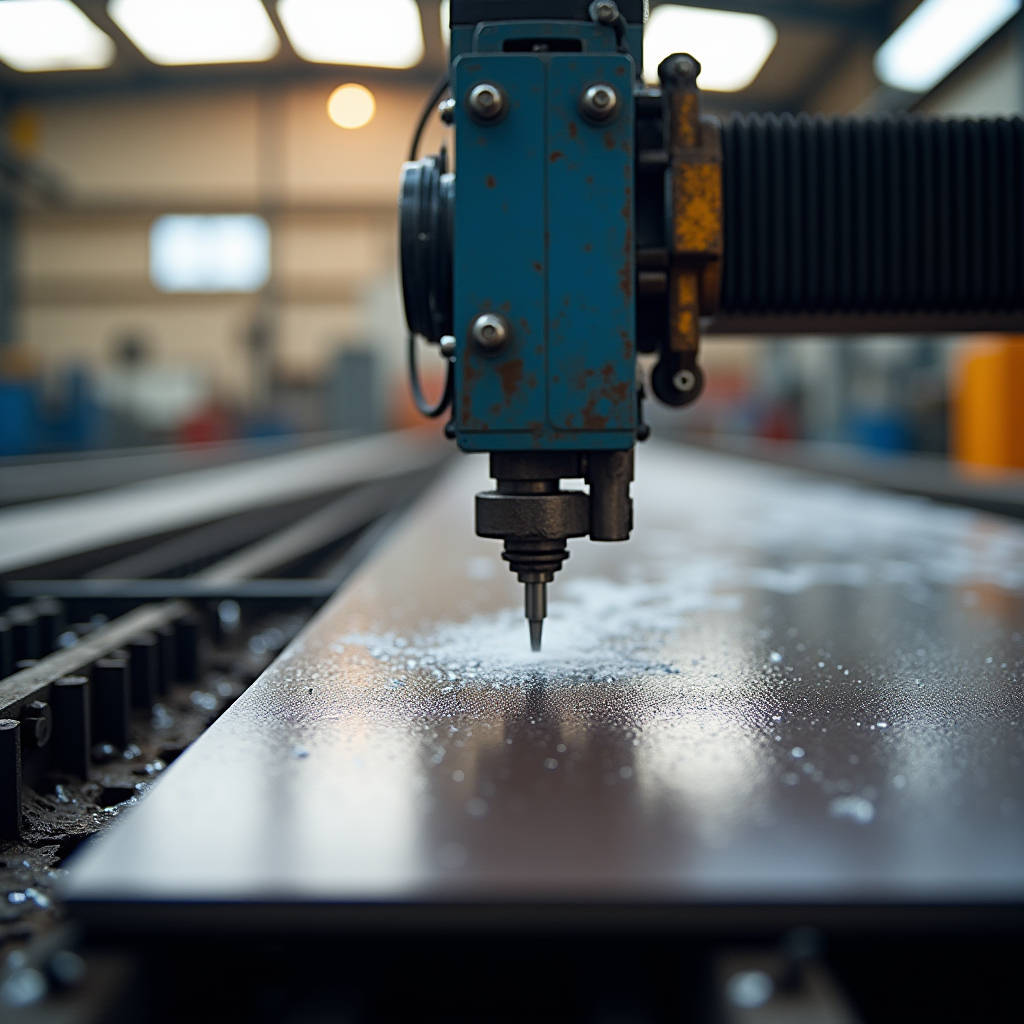
Architectural metal fabrication has shifted substantially over the past decade. Where laser and plasma once dominated the shop floor, waterjet cutting aluminum panel technology now occupies a growing share of the conversation among facade engineers and cladding specialists. The reason is straightforward: solid aluminium panels, typically in thicknesses of 2.0mm, 2.5mm, or 3.0mm with PVDF coatings, demand edge quality and metallurgical integrity that thermal processes cannot reliably deliver. A waterjet cutting aluminum panel workflow eliminates the heat-affected zone entirely, preserves the factory-applied fluoropolymer finish at the cut boundary, and holds dimensional tolerances tight enough for unitized curtain wall assembly. This article examines the specific engineering parameters that matter when specifying waterjet-cut solid aluminium cladding panels, the cost structure across production volumes, and the practical realities of integrating this technology into a facade supply chain.
Why Thermal Cutting Falls Short on Solid Aluminium Cladding
Solid aluminium panel stock in 2.0mm to 3.0mm gauge is not the same material as the structural aluminium extrusions behind the rainscreen. Cladding-grade alloys—typically 3003, 5052, or 5005—are selected for formability, corrosion resistance, and anodizing or PVDF coating compatibility. When a laser or plasma torch hits this material, three things happen that compromise facade performance.
First, the heat-affected zone (HAZ) extends 0.5mm to 2.0mm from the cut edge depending on laser power and feed rate. Within this zone, the grain structure recrystallizes. Yield strength drops measurably. On a 2.0mm panel, a 1.5mm HAZ means nearly the entire cross-section at the edge has altered mechanical properties. For panels that will experience wind-induced cyclic loading, this edge softening is a fatigue risk that no amount of post-cut dressing can fully reverse.
Second, thermal cutting burns the PVDF coating back from the cut line. A typical Kynar 500 or Hylar 5000 coating system runs 25-35 microns dry film thickness. Laser cutting chars this coating 3-5mm into the panel face. The result is a visible dark band that must be mechanically removed or hidden behind a cover flashing—adding labor and limiting design freedom for expressed joints.
Third, aluminium's high thermal conductivity (roughly 205 W/m·K for 5052 alloy) means heat spreads laterally. What starts as a narrow kerf becomes a broad thermal footprint. Thin-gauge cladding panels warp. A 3.0mm panel that was flat to within 0.5mm across a 1200mm span can develop 2-3mm of bow after laser cutting, requiring re-flattening that adds cost and can micro-crack the coating.
Waterjet cutting sidesteps all three problems. The process is purely mechanical erosion. No heat. No HAZ. No coating burn-back. The edge that comes off the waterjet table is the edge that goes onto the building.
How Waterjet Cutting Aluminum Panel Technology Actually Works
The physics are well-established but worth reviewing through the lens of cladding fabrication. A high-pressure pump—typically delivering 60,000 psi (4,137 bar) for architectural aluminium work—forces water through a jewel orifice roughly 0.25mm to 0.35mm in diameter. The resulting stream exits at approximately Mach 3 velocity. Downstream of the orifice, a venturi introduces garnet abrasive, usually 80 mesh for aluminium cladding work. The abrasive-laden jet then strikes the panel surface and erodes a kerf typically 0.8mm to 1.2mm wide.
What matters for the facade engineer is not the jet mechanics but the edge characteristics. A properly dialed waterjet cut on 2.5mm 5052 aluminium produces an edge with surface roughness (Ra) in the 3.2-6.3 micron range—comparable to a fine mill finish. There is no recast layer, no oxide scale, and no micro-cracking. The cut face is ready for edge treatment or can be left exposed in open-joint rainscreen systems where the panel edge is visible.
The cold-cutting nature of the process also means that pre-finished material can be cut directly. A sheet that has already received its full PVDF coating—primer, color coat, and clear coat—can go straight to the waterjet table. This is a significant workflow advantage because it allows fabricators to stock pre-coated coil and cut to order, rather than cutting blanks first and then sending them through the coating line. The latter approach leaves cut edges uncoated and requires edge sealant application as a secondary operation.
Material Considerations for Solid Aluminium Panels
Not all aluminium alloys respond identically to waterjet cutting. The table below summarizes the key alloys used in solid cladding panel fabrication and their waterjet processing characteristics.
| Alloy | Temper | Typical Cladding Gauge | Waterjet Cut Quality | Garnet Mesh Recommendation | Edge RA (μm) |
|---|---|---|---|---|---|
| 3003 | H14 | 2.0-3.0mm | Excellent, minimal burr | 80 mesh | 3.2-4.5 |
| 5052 | H32 | 2.0-3.0mm | Excellent, slight taper on thick stock | 80 mesh | 3.5-5.0 |
| 5005 | H14 | 2.0-2.5mm | Very good, consistent edge | 80 mesh | 3.0-4.0 |
| 6061 | T6 | 3.0mm+ | Good, slower cutting speed required | 80-100 mesh | 4.0-6.3 |
| 1100 | H14 | 2.0-3.0mm | Excellent, very soft alloy | 80 mesh | 2.5-3.5 |
For most architectural cladding applications, 3003-H14 and 5052-H32 are the workhorse alloys. They offer the best balance of formability, corrosion resistance, and waterjet machinability. 6061-T6 appears occasionally in structural panel applications where the cladding also carries load, but its higher silicon content makes the cut edge slightly rougher and cutting speeds drop by roughly 15-20% compared to 5052 at the same thickness.
Garnet selection matters more than many fabricators realize. 80 mesh is the standard for architectural aluminium because it provides sufficient cutting speed without leaving an excessively rough edge. Switching to 120 mesh yields a finer edge but cuts roughly 30% slower. For panels where the cut edge will be visible in an open-joint system, the finer finish may justify the slower throughput. Alluvial garnet is generally preferred over crushed rock garnet for aluminium because the rounded particle shape produces a more consistent kerf.
Cutting Parameters and Speed Data for Cladding Gauges
Production planning requires realistic cutting speed estimates. The figures below assume a 60,000 psi pump, 80 mesh alluvial garnet, and a 0.30mm orifice with a 0.76mm focusing tube. These are representative values based on typical shop conditions; actual speeds will vary with machine rigidity, pump condition, and operator skill.
For 2.0mm 5052-H32 solid aluminium panel stock, linear cutting speed runs approximately 2,800-3,200 mm/min. At this speed, a single cutting head can process roughly 12-15 linear meters per minute of simple perimeter cuts. For a typical 600mm x 1200mm panel with 3,600mm of total cut perimeter, that translates to roughly 1.1-1.3 minutes of actual cutting time per panel.
For 2.5mm stock, speed drops to roughly 2,200-2,600 mm/min. The same 600mm x 1200mm panel now takes 1.4-1.6 minutes. For 3.0mm, expect 1,800-2,100 mm/min and 1.7-2.0 minutes per panel.
These numbers assume straight-line perimeter cuts. Architectural panels rarely involve only straight lines. Perforated panels, panels with integrated louver slots, or panels with complex geometric cutouts will see effective cutting speeds drop by 30-50% depending on the number of pierce points and the complexity of the toolpath. Each pierce takes 2-4 seconds, and for a panel with 200 circular perforations, pierce time alone adds 7-13 minutes per panel.
This is where the economics of waterjet cutting aluminum panel fabrication diverge sharply from laser. Laser cutting is faster on thin-gauge straight cuts—typically 2-3x faster for 2.0mm aluminium. But laser cannot handle the perforated panel scenario without introducing HAZ around every hole. For complex architectural geometries, waterjet is not just the better-quality option; it is often the only viable option that preserves coating integrity and edge metallurgy.
Taper, Stream Lag, and the Geometry Challenges
Waterjet cutting is not geometrically perfect. Two phenomena affect cut accuracy on solid aluminium panels: taper and stream lag.
Taper refers to the V-shaped kerf that results from the jet losing energy as it passes through the material. The entry side of the cut is slightly wider than the exit side. On 2.0mm 5052 aluminium, taper is typically 0.05-0.10mm—barely measurable and irrelevant for cladding tolerances. On 3.0mm stock, taper can reach 0.15mm. For most architectural work, this is still within acceptable limits. But for panels that require extremely tight fit-up with adjacent panels or framing members, the taper direction must be accounted for in the toolpath. The standard practice is to orient the jet entry side as the visible face of the panel, so the slightly wider kerf opening faces outward and any taper-induced gap is hidden behind the panel.
Stream lag is more consequential for complex geometries. As the cutting head moves through corners and tight radii, the jet bends—the exit point lags behind the entry point. On a sharp 90-degree corner cut at 2,500 mm/min, the exit stream can lag by 0.3-0.5mm. The result is a corner that is not perfectly square on the back face of the panel. For cladding panels with interlocking edges or panels that must fit precisely into a unitized frame, this lag can cause assembly problems.
The solution is dynamic head control or corner slowdown. Modern 5-axis waterjet heads can tilt to compensate for stream lag, maintaining a square cut face through corners. On 3-axis machines, the operator programs a speed reduction through corners—typically to 10-15% of straight-line speed—which minimizes lag but increases cycle time. For architectural panels with numerous cutouts, the choice between 5-axis and 3-axis machines has direct cost implications that should be specified in the fabrication scope.
Cost Structure and Production Economics
Understanding the cost drivers of waterjet cutting aluminum panel fabrication helps procurement managers make informed decisions about whether to specify waterjet or accept alternative cutting methods. The cost structure breaks down into machine amortization, abrasive consumption, pump maintenance, and labor.
Abrasive is the largest consumable cost. At typical flow rates of 0.5-0.7 kg/min of garnet, a single cutting head consumes roughly 30-42 kg per hour of continuous cutting. With alluvial 80-mesh garnet priced at approximately $0.50-0.80 per kg delivered in most markets, abrasive cost runs $15-34 per hour. For a panel that takes 2 minutes of cutting time, abrasive cost is $0.50-1.15 per panel.
Pump rebuild costs are the second major variable. High-pressure pump seals and check valves require rebuilding every 500-1,000 operating hours depending on water quality and operating pressure. A typical rebuild costs $3,000-6,000 in parts and labor. Amortized over 750 hours, that adds $4-8 per hour to the machine rate.
When all costs are tallied—machine lease or depreciation, abrasive, pump maintenance, water treatment, labor, and overhead—the fully burdened hourly rate for a single-head waterjet cutting cell typically falls in the $120-180 range. At 2 minutes per panel, that is $4-6 per panel for cutting. This compares favorably with laser cutting at $3-5 per panel for simple geometries, but the waterjet advantage emerges when factoring in the elimination of post-cut edge dressing, coating touch-up, and re-flattening operations that thermal cutting requires.
For project-scale procurement, the cost premium for waterjet cutting aluminum panel work over laser cutting is typically 10-20% on the cutting operation alone, but the total fabricated panel cost difference often shrinks to 5-10% or less once downstream labor savings are included. On projects where edge quality is critical—open-joint systems, expressed shadow gaps, panels with visible perforations—the waterjet premium is essentially self-justifying.
Coating Compatibility and Edge Treatment
The interaction between waterjet cutting and PVDF coating systems deserves specific attention. Solid aluminium panels for exterior cladding are almost universally finished with a 70% PVDF resin-based coating system—Kynar 500 or Hylar 5000 being the dominant resin brands. These systems are applied in a coil coating or spray coating process and cured at temperatures of 230-250°C.
When a waterjet cuts through a pre-coated panel, the coating at the cut edge is mechanically removed along with the aluminium substrate. The coating adjacent to the cut—within 0.1-0.2mm of the kerf—remains intact and fully adhered. There is no delamination risk because the cutting mechanism is purely mechanical erosion, not thermal shock or chemical attack.
This is a critical distinction from laser cutting, where the thermal pulse can delaminate the coating 2-5mm back from the cut line. On a panel with a 10mm expressed joint, a 5mm delamination band means half the visible joint width shows coating damage. Waterjet eliminates this problem entirely.
However, the cut edge itself is bare aluminium. For most rainscreen applications, the cut edge is hidden behind the panel or within a joint that is not directly exposed to weather. In these cases, no edge treatment is required beyond deburring. For open-joint systems where the panel edge is visible, a clear edge sealant or touch-up coating may be specified for aesthetic reasons rather than corrosion protection, since the 5000-series and 3000-series alloys used in cladding have excellent atmospheric corrosion resistance on their own.
For coastal or aggressive industrial environments, edge treatment becomes a corrosion consideration. A thin application of clear chromate conversion coating followed by a clear organic sealant provides additional protection without altering the visual appearance of the cut edge. This is a standard practice that should be specified in the fabrication scope for projects within 5km of saltwater or in heavy industrial zones.
Perforated Panels and Architectural Geometry
The strongest case for waterjet cutting aluminum panel technology in architectural applications is perforated cladding. Perforated solid aluminium panels serve multiple functions: solar shading, ventilation screening, acoustic absorption when backed with insulation, and purely aesthetic patterning. The perforation geometries range from simple circular holes on a grid pattern to custom artistic perforations that require thousands of unique pierce points.
Waterjet is uniquely suited to this work because each perforation is cut with the same cold process as the panel perimeter. There is no cumulative heat buildup, no coating damage around each hole, and no limitation on hole geometry. Slots, hexagons, irregular organic shapes—all are equally feasible with waterjet.
The production challenge with perforated panels is cycle time. A panel with 500 circular perforations requires 500 pierce points. At 3 seconds per pierce, that is 25 minutes of pierce time alone, plus the cutting time for each hole perimeter. For a 2.0mm panel with 20mm diameter holes, each hole perimeter is 63mm, and at 3,000 mm/min, each hole cuts in 1.3 seconds. Total time per hole: 4.3 seconds. 500 holes: 36 minutes. Add the panel perimeter cut and the total cycle time per panel approaches 40 minutes.
At a fully burdened machine rate of $150/hour, that is $100 per panel for cutting alone. This is where the value engineering conversation becomes important. Reducing perforation count, increasing hole diameter, or switching to a simpler pattern can dramatically reduce cutting time without compromising the design intent. The architect and fabricator should collaborate early in the design phase to optimize perforation geometry for waterjet efficiency.
Futeng® has supplied waterjet-cut perforated solid aluminium panels for multiple commercial facade projects where the perforation pattern was integral to the building's environmental performance strategy. The key lesson from those projects is that early collaboration between the design team and the fabrication team on perforation parameters consistently yields a 15-25% reduction in fabrication cost compared to designs developed without fabrication input.
Quality Control and Dimensional Verification
Specifying waterjet cutting aluminum panel fabrication requires a clear quality control framework. The relevant standards include ISO 2768 for general tolerances and ASTM E1155 for flatness measurement of floor and wall surfaces, which can be adapted for panel flatness verification.
For a typical 600mm x 1200mm solid aluminium cladding panel, the dimensional tolerances achievable with waterjet cutting are as follows: length and width within ±0.25mm, diagonal difference within 0.4mm, hole position within ±0.15mm of nominal, and edge squareness within 0.3mm across the full panel diagonal. These tolerances are tighter than what is achievable with shearing or routing and are comparable to laser cutting, but without the HAZ penalty.
Flatness after cutting should be verified against the project specification. A 2.5mm panel that enters the waterjet table with 0.5mm flatness across the diagonal should exit with the same flatness. If it does not, the cause is likely residual stress release in the sheet rather than the cutting process itself. This is a material quality issue, not a cutting issue, and should be addressed with the aluminium supplier.
First-article inspection is essential for waterjet-cut architectural panels. The first panel from each batch should be measured on a coordinate measuring machine (CMM) or with a calibrated vision system to verify all critical dimensions before production cutting begins. This is standard practice in aerospace and automotive aluminium fabrication and should be equally standard in architectural metalwork.
Integrating Waterjet Cutting into the Facade Supply Chain
For the general contractor or facade subcontractor, the decision to specify waterjet cutting is not just a technical choice—it is a supply chain decision. Waterjet capacity is not universally available in every market, and lead times can be longer than for conventional cutting methods.
The typical workflow for a waterjet-cut solid aluminium panel package runs as follows: the aluminium coil or sheet stock is received and inspected, pre-coated if the coating strategy calls for post-coating, then cut on the waterjet table, deburred, edge-treated if specified, inspected, packed, and shipped. Total lead time from material receipt to shipment is typically 3-5 weeks for a 1,000-panel package, depending on geometry complexity and perforation requirements.
This is roughly 1-2 weeks longer than the same package cut by laser or shear, but the downstream installation time savings often offset the fabrication lead time. Waterjet-cut panels fit together more precisely on site, require less field adjustment, and eliminate the need for coating touch-up at cut edges. For a unitized curtain wall system where panel fit-up tolerance is critical, the waterjet premium in fabrication often pays for itself in reduced site labor.
Specifiers should also consider that waterjet cutting is a relatively low-utilization process for thin-gauge aluminium. A single cutting head can process 30-60 panels per shift for simple perimeter cuts, but only 8-15 panels per shift for heavily perforated designs. The fabricator's capacity planning must account for this variability, and project schedules should allow realistic cutting durations for complex geometries.
Environmental and Shop Safety Considerations
Waterjet cutting generates two waste streams: spent garnet and aluminium sludge. The garnet, once it has passed through the cutting kerf, is fractured and mixed with eroded aluminium particles. It cannot be reused for cutting but can be recycled as sandblasting media or construction aggregate. Some fabricators send spent garnet to cement kilns as a silica source. The aluminium content in the sludge can be recovered through filtration and sent to aluminium recyclers, though the economics of recovery depend on volume and local recycling infrastructure.
Water consumption is another consideration. A typical waterjet cutting cell uses 3-8 liters of water per minute, most of which is recirculated through a closed-loop filtration system. Makeup water requirements are modest—typically 0.5-1.0 liters per minute of fresh water to replace evaporation and carry-out losses. For a single-shift operation, daily water consumption is in the range of 200-500 liters, comparable to a small commercial dishwasher.
Noise is the primary shop-floor concern. The cutting process itself generates 85-95 dBA at the operator position, requiring hearing protection. The pump room is typically isolated from the cutting area to reduce operator exposure. These are standard industrial hygiene considerations and should be addressed in the fabricator's health and safety plan.
From a sustainability perspective, waterjet cutting aligns well with the environmental goals of modern architectural projects. The process generates no fumes, no hazardous air pollutants, and no ozone-depleting substances. The cold-cutting mechanism means no energy is wasted heating material that will simply be discarded as kerf waste. For projects targeting LEED or BREEAM credits, specifying waterjet-cut aluminium panels can contribute to the material and resource credit categories.
Practical Specification Guidance for Project Teams
When writing a specification for waterjet-cut solid aluminium cladding panels, several key parameters should be explicitly stated to ensure the fabricated product meets project requirements.
First, specify the alloy and temper. "Aluminium alloy 5052-H32 per ASTM B209" is a complete specification that leaves no ambiguity. Do not simply write "aluminium sheet"—this invites substitution of lower-grade alloys that may not perform adequately in waterjet cutting or in service.
Second, specify the cutting method explicitly. "All panels shall be cut by abrasive waterjet. Thermal cutting methods (laser, plasma) are not permitted." This is a simple statement that eliminates the risk of the fabricator substituting a cheaper thermal process.
Third, specify edge quality requirements. Reference a surface roughness value (Ra) and a visual acceptance standard. "Cut edges shall have a surface roughness not exceeding Ra 6.3 μm. Edge coating shall be intact and fully adhered within 0.5mm of the cut line. No coating burn-back, discoloration, or delamination is acceptable."
Fourth, specify dimensional tolerances. Reference ISO 2768-mK or a project-specific tolerance schedule. For unitized systems, consider tightening the standard tolerances to ±0.2mm on critical dimensions.
Fifth, require a first-article inspection report with dimensional verification data before production cutting begins. This single requirement prevents more disputes than any other specification clause.
Finally, require the fabricator to submit their garnet specification and water quality management plan. Garnet type and mesh size directly affect edge quality, and poor water quality accelerates pump wear and can introduce contaminants into the cut surface.
Waterjet cutting aluminum panel fabrication is a mature, well-characterized process that delivers measurable quality advantages for architectural cladding applications. The technology is not new—waterjet cutting has been used in aerospace for decades—but its adoption in facade engineering has accelerated as project teams recognize that the edge quality, coating integrity, and geometric flexibility it provides directly address the failure modes that plague thermally cut aluminium panels. For the specifier, the key is understanding the process parameters well enough to write a specification that captures the quality benefits without over-specifying to the point of eliminating qualified fabricators. For the contractor, the key is recognizing that the modest cost premium for waterjet cutting is typically recovered through reduced site labor, fewer quality rejections, and a facade system that performs as designed over the building's service life.