Aluminum Panel Roll Bending for Curved Architectural Facades Technical Engineering Guide
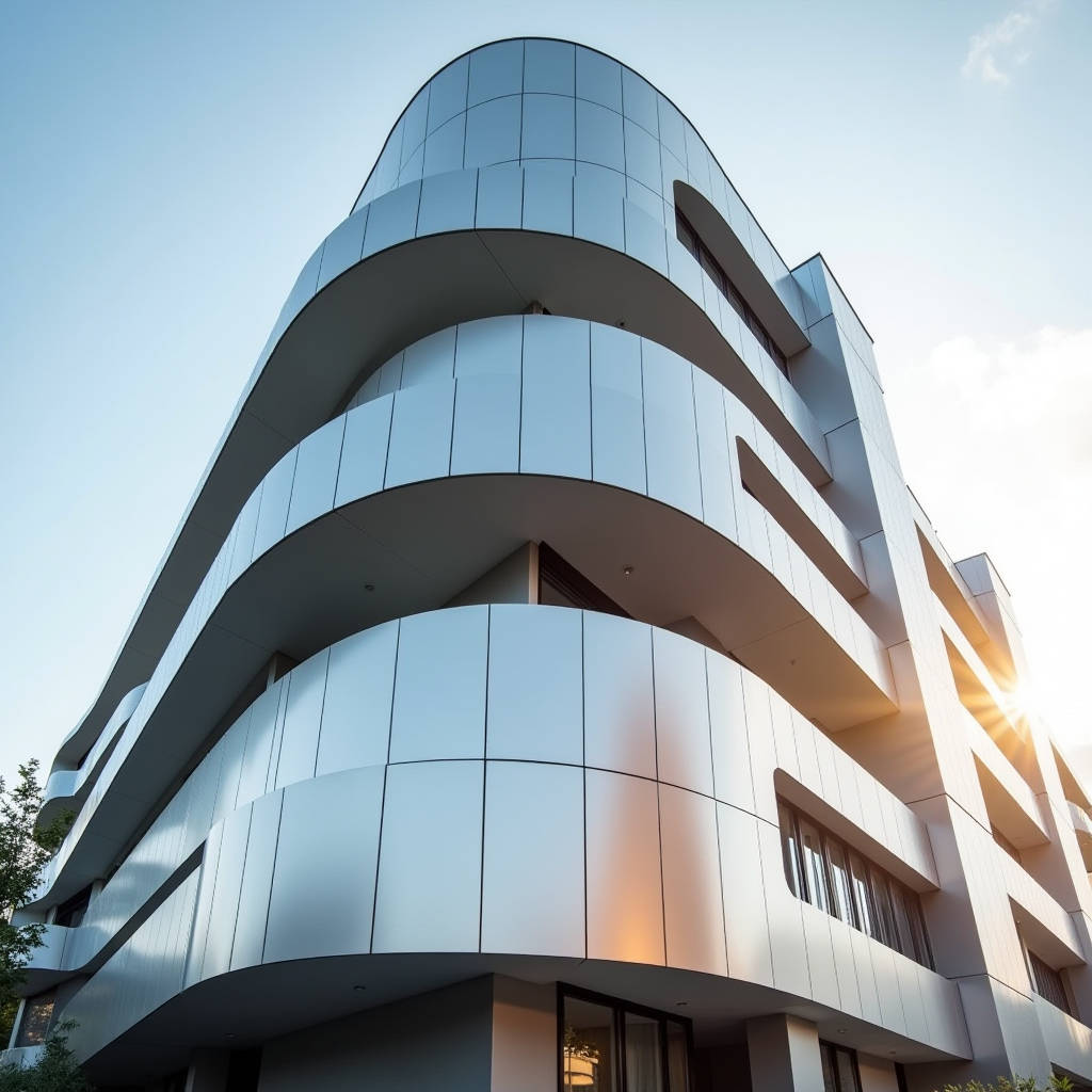
Aluminum Panel Roll Bending is the industrial forming process that transforms flat solid aluminium sheets into curved architectural cladding elements using a series of powered rollers. For facade contractors and building envelope specialists, this technique solves a fundamental design problem: how to achieve smooth, continuous radius geometries on large-format aluminium panels without compromising structural integrity or surface finish. Unlike press brake forming, which creates segmented bends, roll bending produces a true arc through gradual plastic deformation. The process demands precise control over roller positioning, feed rate, and material springback compensation. When executed correctly on solid aluminium sheets in the 2.0mm to 3.0mm thickness range, roll bending delivers curved panels that meet the flatness tolerances specified in AAMA 609.1 while maintaining the PVDF coating integrity that architects specify for 20-year exterior performance.
Why Solid Aluminium Demands a Different Roll Bending Approach
Solid aluminium cladding panels behave fundamentally differently from composite materials during roll bending. A 2.5mm or 3.0mm monolithic 3003-H14 or 5052-H32 sheet has a uniform cross-section with no polyethylene core, no thin outer skins, and no adhesive layers that can delaminate under bending stress. This homogeneity is both an advantage and a technical challenge. The advantage: there is no risk of core separation, no differential springback between skin layers, and no limitation on bend radius imposed by composite construction. The challenge: solid aluminium work-hardens during plastic deformation, meaning the material becomes progressively stiffer and more resistant to further bending as the rollers apply force. Operators must account for this by adjusting roller pressure dynamically through multi-pass sequences. A typical 2.5mm 5052-H32 panel might require 4 to 7 passes through a four-roll machine to achieve a 1500mm radius without inducing surface ripples or edge wave defects. The yield strength of 5052-H32 sits around 193 MPa, which gives fabricators a predictable window for plastic deformation before reaching the ultimate tensile strength of approximately 228 MPa.
Alloy Selection for Roll Bending Solid Aluminium Facade Panels
The choice of aluminium alloy directly determines roll bending success rates, minimum achievable radii, and long-term facade performance. Three alloys dominate the architectural cladding sector: 3003, 5052, and 5005. Each brings distinct forming characteristics to the roll bending process.
3003-H14 is the most formable of the three, with an elongation at break of approximately 8-10% and a yield strength of around 145 MPa. This alloy bends easily and accepts tight radii without cracking. However, its lower tensile strength means panels in high-wind zones may require thicker gauges, which increases material cost and dead load on the building structure. 5052-H32 offers a sweet spot for architectural roll bending. With magnesium as the primary alloying element, it delivers yield strength near 193 MPa and elongation of 7-9%. The higher strength allows specifiers to use 2.0mm or 2.5mm sheets where 3003 might require 3.0mm. 5005-H14 sits between these two in strength and formability, and its surface quality after anodizing makes it popular for interior architectural applications, though it is less common for large exterior curved panels where PVDF fluoropolymer coatings are specified.
Fabricators working with 6061-T6 should exercise caution. This heat-treated alloy has yield strength exceeding 276 MPa but elongation of only 8% in thin gauges. Roll bending 6061-T6 into tight architectural radii frequently results in cracking at the outer fiber unless the material is first annealed to the O condition, formed, and then re-heat-treated. This adds significant cost and lead time. For most curved facade projects, 5052-H32 or 3003-H14 in the as-supplied temper provides the best balance of formability, strength, and coating adhesion.
Roll Bending Machine Configurations and Their Architectural Output
Three machine configurations dominate the architectural aluminium panel roll bending industry: three-roll pyramid machines, three-roll initial pinch machines, and four-roll double-pinch machines. Each produces different flat-end characteristics and radius consistency, which directly affect panel-to-panel joint alignment on curved facades.
Three-roll pyramid machines position two lower rollers on a fixed plane with a single upper roller applying downward pressure. The panel enters and exits between the lower rollers and the upper roller. This configuration leaves a short flat section at both the leading and trailing edges of the panel because the material cannot be bent until it contacts all three rollers simultaneously. For architectural panels, this flat section typically measures 2 to 3 times the material thickness in length. On a 2.5mm panel, the unbent flat tail might be 5mm to 7.5mm, which is often acceptable for panels that will be trimmed or where the flat section falls within the panel's attachment zone.
Four-roll double-pinch machines address the flat-end problem more effectively. With two driven lower rollers and two adjustable upper rollers, the machine can pinch the material between the upper and lower rollers at both the infeed and outfeed sides. This allows the operator to bend the panel almost to its very edge. For architectural applications where curved panels must meet at expansion joints with consistent gap widths, four-roll machines produce more predictable results. The trade-off is higher machine cost and more complex setup, which typically adds 15-25% to the per-panel processing cost compared to three-roll pyramid bending.
Springback Compensation: The Mathematics Behind Accurate Curved Facades
Springback is the elastic recovery that occurs when a roll-bent aluminium panel is released from the machine. The panel will always open up slightly from the radius set by the rollers, and the magnitude of this springback depends on the alloy, temper, thickness, and bend radius. Ignoring springback compensation produces panels that do not match the architect's specified radius, creating alignment problems during installation.
The springback factor Ks can be estimated using the formula Ks = 1 - (3 × YS × R) / (E × T), where YS is the yield strength of the alloy, R is the desired inside radius, E is the elastic modulus (approximately 69 GPa for aluminium), and T is the material thickness. For a 2.5mm 5052-H32 panel being bent to a 2000mm radius, the calculation yields a springback factor of approximately 0.93. This means the roller must be set to produce a radius roughly 7% tighter than the target radius. In practice, experienced operators at facilities like Futeng® validate these calculations with test bends on offcut material from the same batch, measuring the resulting radius with templates and adjusting the machine settings accordingly. Batch-to-batch variation in temper can shift springback by 1-2%, so testing each material lot is standard practice for high-tolerance architectural work.
| Alloy & Temper | Thickness (mm) | Target Radius (mm) | Estimated Springback (%) | Required Roller Radius (mm) | Typical Passes |
|---|---|---|---|---|---|
| 3003-H14 | 2.0 | 1000 | 5.2 | 948 | 3-5 |
| 3003-H14 | 3.0 | 2000 | 4.1 | 1918 | 4-6 |
| 5052-H32 | 2.0 | 1000 | 7.8 | 922 | 5-7 |
| 5052-H32 | 2.5 | 1500 | 7.0 | 1395 | 4-7 |
| 5052-H32 | 3.0 | 2000 | 6.3 | 1874 | 5-8 |
| 5005-H14 | 2.5 | 1800 | 5.8 | 1696 | 4-6 |
Minimum Bend Radius: Avoiding Fracture in Architectural Panels
Every aluminium alloy and temper has a minimum bend radius below which the outer fiber of the material will crack. For architectural cladding where the panel face is visible, even micro-cracking is unacceptable because it creates pathways for moisture ingress and compromises the PVDF coating's protective function. The minimum inside bend radius for roll bending is typically expressed as a multiple of material thickness.
For 3003-H14, the minimum inside radius is approximately 1.0 to 1.5 times the sheet thickness. A 2.5mm panel can therefore be bent to a radius as tight as 2.5mm to 3.75mm, though such tight radii are rarely specified in architectural facades. 5052-H32 requires a more generous minimum radius of 1.5 to 2.5 times thickness, meaning a 2.5mm panel should not be bent tighter than approximately 3.75mm to 6.25mm inside radius. 5005-H14 falls between these ranges at approximately 1.0 to 2.0 times thickness. These are minimum values for avoiding fracture; architectural specifications often require larger radii for aesthetic reasons, as tighter bends can produce visible surface distortion on the outer face of the panel. The Aluminum Association publishes detailed forming limit diagrams that provide alloy-specific bend radius recommendations based on extensive testing data.
Coating Integrity During Roll Bending: PVDF and FEVE Considerations
Architectural aluminium panels are almost always roll-bent after coating, which introduces a critical quality concern: will the PVDF or FEVE fluoropolymer coating survive the bending process without cracking, delaminating, or losing adhesion? The answer depends on coating formulation, film thickness, and the severity of the bend.
Standard 70% PVDF coatings, applied at 25-35 microns dry film thickness per AAMA 2605 specifications, exhibit sufficient elasticity to withstand moderate roll bending. The coating's elongation capability typically exceeds 50%, which is far greater than the elongation of the aluminium substrate. However, the coating-substrate interface is the vulnerable point. If pretreatment was inadequate or if the primer layer was applied too thinly, the shear stress at the bend's outer surface can cause micro-delamination that may not be visible immediately but will manifest as blistering or peeling within 2-5 years of exterior exposure.
For tight-radius architectural bends, fabricators should specify a high-elongation primer system and verify coating adhesion through cross-hatch testing per ASTM D3359 on bent samples before committing to full production. Some PVDF coating suppliers offer formulations specifically engineered for post-forming applications, with modified resin systems that provide enhanced flexibility. The incremental cost of these specialized coatings is typically $3-7 per square meter, which is negligible compared to the cost of replacing failed panels on an installed facade.
Multi-Radius and Compound Curvature: Beyond Simple Cylindrical Panels
While single-radius cylindrical panels represent the majority of roll-bent architectural work, many contemporary facade designs demand multi-radius curves, conical sections, or panels with a gradually changing radius along their length. These geometries push the capabilities of conventional roll bending equipment and require advanced programming and operator expertise.
Multi-radius bending involves programming the roller positions to change during the bending pass, creating a panel with two or more distinct radii. A typical application might be a panel that transitions from a 3000mm radius at the building's base to a 1500mm radius at the parapet. CNC-controlled four-roll machines can execute these transitions smoothly by varying the upper roller position in real-time as the panel feeds through. The programming challenge lies in predicting how the changing roller position will interact with springback at each point along the curve. Most modern controllers use algorithms that interpolate springback compensation across the radius range, but the first panel from each batch should always be checked against a full-scale template.
Conical roll bending, used for curved spandrel panels on tapered building forms, requires the rollers to be set at an angle to each other so that one edge of the panel travels a shorter path than the opposite edge. This produces a panel that is curved in one axis and tapered in the perpendicular axis. The setup time for conical bending can be 3-4 times longer than for cylindrical bending, and the scrap rate on first articles is higher. Contractors should budget for 5-10% material waste on complex multi-radius or conical panel orders.
Quality Control and Dimensional Verification for Curved Panels
Verifying the radius of a roll-bent aluminium panel is more challenging than checking the angle of a press-braked part. The industry relies on three primary methods: full-scale templates, chord-height measurement, and coordinate measuring systems.
Full-scale templates cut from plywood or MDF remain the most practical method for architectural panels up to 3 meters in length. The panel is placed against the template, and gaps are measured with feeler gauges. A tolerance of ±2mm over the panel's arc length is achievable and is specified in many architectural metalwork standards. For more precise verification, the chord-height method uses a straightedge of known length placed across the concave face of the panel, with the gap at the midpoint measured and converted to radius using simple geometry. For a chord length L and a measured gap H, the radius R = (L²/8H) + (H/2).
Laser scanning and photogrammetry are increasingly used for quality control on large curved facade projects. These systems capture the full 3D surface geometry of each panel and compare it to the BIM model, generating a color-coded deviation map. The AAMA 609.1 standard provides performance requirements for factory-applied coatings on architectural aluminium, and while it does not directly address dimensional tolerances for curved panels, it establishes the quality framework that should be maintained throughout the fabrication process.
Cost Drivers in Architectural Roll Bending Projects
Understanding what drives the cost of roll-bent aluminium panels helps procurement managers budget accurately and avoid change orders. The primary cost factors are alloy selection, material thickness, radius complexity, coating requirements, and production volume.
Material cost scales with thickness. A 3.0mm 5052-H32 sheet costs approximately 50% more per square meter than a 2.0mm sheet of the same alloy. For a 10,000 square meter curved facade, the material cost difference between 2.0mm and 3.0mm can exceed $150,000. This is why structural engineering analysis should be performed early to determine the minimum acceptable thickness for wind load resistance, rather than defaulting to a conservative 3.0mm specification.
Processing cost is dominated by machine time and setup labor. A simple single-radius panel might require 15-20 minutes of machine time including setup, while a multi-radius or conical panel could require 45-60 minutes. At shop rates of $120-180 per hour for architectural metal fabrication, the processing cost difference between simple and complex geometries can be $60-120 per panel. For projects with hundreds of unique panel geometries, the cumulative setup cost can exceed the material cost. Standardizing panel radii across the facade design, where architecturally feasible, is one of the most effective cost-reduction strategies available to the design team.
Transportation and Handling of Curved Aluminium Panels
Curved panels present unique logistics challenges that flat panels do not. The curvature creates void space in shipping containers and on trucks, reducing packing density and increasing freight cost per panel. A 40-foot container that can hold 800 flat panels might only accommodate 400-500 curved panels depending on radius and stacking configuration.
Stacking curved panels requires purpose-built stillages or cradles that support the panels along their arc and prevent them from deforming under their own weight during transit. Panels with a convex-up orientation are particularly vulnerable to flattening if stacked too high. The general rule is that stack height should not exceed 1.2 meters for curved panels, and each panel should be separated by protective interleaving material. For overseas shipments, where panels may be subjected to multiple handling cycles and extended transit times, wooden crating with internal foam supports is standard practice. These crating costs can add $8-15 per square meter to the delivered panel cost.
Installation teams also need to be prepared for curved panel handling. Suction cup lifters designed for flat panels may not achieve adequate seal on curved surfaces. Mechanical clamps with padded jaws are often substituted, and larger panels may require spreader bars to prevent bending during lifting. The ASTM E1300 standard for structural performance of architectural glass, while not directly applicable to aluminium panels, provides a useful reference framework for understanding how curved geometries affect load distribution during handling.
Thermal Movement in Curved Aluminium Facades
Aluminium expands and contracts at approximately 0.024mm per meter per degree Celsius. On a 6-meter-long curved panel subjected to a 60°C temperature swing between summer sun and winter night, the total length change approaches 8.6mm. Curved panels respond to thermal movement differently than flat panels because the curvature introduces a geometric constraint: as the panel tries to expand linearly, the radius must change slightly to accommodate the new length.
If the panel is rigidly fixed at both ends, thermal expansion forces can cause buckling or oil-canning of the curved surface. The standard solution is to fix the panel at one end and allow the opposite end to slide within a slotted connection. The slot length must accommodate the full calculated thermal movement plus a safety margin. For the 6-meter panel example, a slot providing at least 12mm of travel is appropriate. The attachment system must also allow the panel's radius to change slightly without binding. This is typically achieved through slotted holes at intermediate attachment points, oriented perpendicular to the panel's curve direction.
For projects in extreme climates, such as Middle Eastern or Scandinavian locations where annual temperature ranges can exceed 70°C, thermal movement calculations should be performed by the facade engineer and incorporated into the shop drawings. The ISO 10545 series on thermal expansion provides testing methodologies that can be adapted for architectural metal panel systems.
Specifying Roll Bending Tolerances for Contract Documents
Ambiguous tolerance specifications are a common source of disputes between architects, general contractors, and panel fabricators. A specification that simply states "panels shall be curved to the radius shown on the architectural drawings" provides no objective acceptance criteria. Effective specifications define the permitted deviation from the nominal radius, the method of measurement, and the sampling rate for inspection.
A practical tolerance specification for architectural roll-bent panels might read: "The radius of curvature at any point along the panel shall not deviate from the specified radius by more than ±2% or ±5mm, whichever is greater. Measurement shall be by chord-height method using a 1000mm straightedge or by comparison to a full-scale template. Sampling rate shall be 100% for the first 10 panels of each unique radius, reducing to 10% random sampling thereafter if all first-article panels meet tolerance." This approach balances quality assurance with practical inspection costs and provides clear pass/fail criteria that all parties can agree on before fabrication begins.
For panels that will be installed adjacent to each other on a continuous curved facade, an additional tolerance on gap consistency should be specified. The joint width between adjacent curved panels should not vary by more than ±1.5mm from the nominal joint width specified in the architectural drawings. This tolerance is tighter than the radius tolerance and may require selective panel matching during installation, where panels are dry-fitted and paired to achieve consistent joints before final fixing.
Integrating Roll-Bent Panels with Substructure and Weather Barriers
The curved aluminium panel is only one component of a complete rainscreen system. The supporting substructure, thermal insulation, air and weather barriers, and attachment hardware must all accommodate the curved geometry without compromising performance. This integration is where many curved facade projects encounter coordination problems.
The substructure for curved panels typically uses curved aluminum extrusions or segmented steel sections that approximate the panel radius. Curved extrusions are more expensive than straight sections but provide continuous support and eliminate the faceted appearance that segmented supports can create. The cost premium for curved aluminium extrusions over straight sections of the same profile ranges from 30-80% depending on radius and quantity. For large-radius curves above 5000mm, segmented straight supports with shimmed attachment points often provide adequate support at lower cost, because the chord-to-arc deviation over a 1200mm support spacing is less than 1mm.
The air and weather barrier behind curved panels must be detailed to prevent water penetration at the curved surface. Self-adhered membrane barriers conform well to moderate curves but may wrinkle on tight radii. Fluid-applied barriers eliminate this problem but require careful thickness control during application. The National Fenestration Rating Council provides relevant performance criteria for building envelope components, though their primary focus is on fenestration products rather than opaque cladding systems.
Successful curved facade projects depend on early collaboration between the architect, facade engineer, panel fabricator, and installer. When the panel fabricator is engaged during the design development phase rather than after construction documents are complete, potential fabrication and installation issues can be identified and resolved before they become change orders. This collaborative approach typically reduces the overall curved facade cost by 10-15% compared to projects where the fabricator is brought in only after the design is finalized and tendered.