Aluminum Panel Spot Welding Parameters and Quality Control for Solid Aluminium Cladding Fabrication
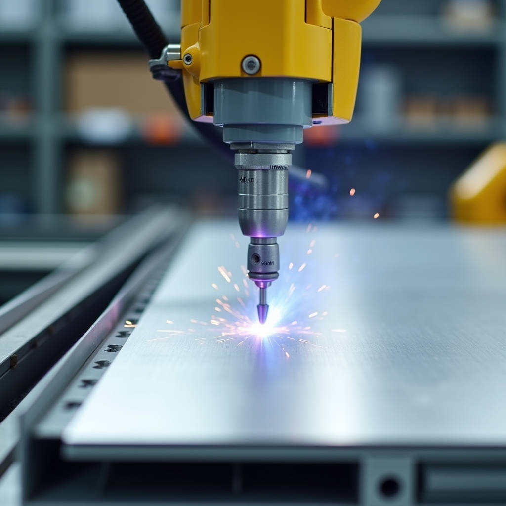
Spot welding aluminum panels presents a set of challenges that general steel welding knowledge simply does not cover. Aluminum's high thermal conductivity, low electrical resistance, and rapid surface oxidation demand a fundamentally different approach to resistance welding. For facade engineers and cladding contractors working with solid aluminium sheets in the 2.0mm to 3.0mm range, getting the weld parameters wrong means burn-through, weak nugget formation, or electrode damage that escalates project costs. This article examines the specific variables that determine success in Aluminum Panel Spot Welding for architectural applications, from electrode material selection and surface preparation protocols to the weld schedule adjustments that account for PVDF-coated surfaces. The focus stays on the production floor realities: how to achieve consistent joint strength across large-format panels, what quality control checks actually catch defects before panels leave the shop, and where the economics of spot welding hold up against mechanical fastening and structural adhesive bonding in curtain wall fabrication.
Why Aluminum Panel Spot Welding Demands a Different Approach
Aluminum does not behave like steel under a spot welding electrode. The metal's electrical conductivity is roughly four times higher than carbon steel, which means the current needed to generate sufficient resistive heat at the weld interface must be significantly higher — often two to three times the amperage used for an equivalent steel thickness. At the same time, aluminum's thermal conductivity pulls heat away from the weld zone almost as fast as it builds up. The window between "enough heat to form a nugget" and "too much heat causing expulsion or burn-through" shrinks dramatically.
The oxide layer complicates things further. Aluminum forms a tenacious aluminum oxide film within seconds of exposure to air. This oxide has a melting point around 2,050°C, while the base aluminum underneath melts at roughly 660°C. During Aluminum Panel Spot Welding, the oxide layer acts as an electrical insulator at the faying surfaces, creating inconsistent contact resistance. If the oxide is not removed or broken through by sufficient electrode force, the weld current arcs unpredictably, producing surface spatter and weak or non-existent nuggets.
For cladding panels in the 2.0mm to 3.0mm thickness range, these physical properties translate into three practical requirements: power supplies capable of delivering 20,000 to 40,000 amps in short, precisely timed pulses; electrode materials that resist rapid degradation from the combination of high current and aluminum's tendency to alloy with copper; and surface preparation steps that cannot be skipped without compromising every weld on the line.
Equipment That Actually Works for Architectural Aluminum
Power Supply: Why Standard AC Machines Fall Short
Conventional single-phase AC spot welders, the kind found in most general fabrication shops, struggle with aluminum for a fundamental reason: they cannot deliver the combination of high current and short weld time that the material requires. Aluminum spot welding typically needs weld times between 2 and 8 cycles (at 50/60 Hz), compared to 10 to 30 cycles for steel of similar thickness. When an AC machine tries to push 30,000 amps through aluminum in 4 cycles, the inductive reactance in the secondary circuit chokes the current, and the weld pulse shape becomes inconsistent.
Three power supply technologies have proven effective for Aluminum Panel Spot Welding in production environments:
- Medium-Frequency Direct Current (MFDC): Inverts the incoming AC to 1,000 Hz before transforming and rectifying to DC. This eliminates inductive losses, delivers a flat current profile, and allows precise control of upslope and downslope. MFDC is the workhorse for architectural aluminum fabrication, handling 2.0mm to 3.0mm sheet with repeatable results.
- Capacitor Discharge (CD): Stores energy in a capacitor bank and releases it in a single, extremely short pulse (typically 5 to 20 milliseconds). CD welders excel at joining thin aluminum sheets where heat input must be minimized, and they draw relatively low line power, making them practical for shops without heavy electrical infrastructure.
- Transistor-Controlled High-Frequency Inverters: Offer the finest control over weld pulse shaping, with the ability to program multi-pulse schedules that manage the oxide layer and control nugget solidification. These systems are more expensive but provide the consistency needed for high-volume panel production.
Electrode Materials and Geometry
Copper electrodes, standard for steel spot welding, degrade rapidly when welding aluminum. The combination of high current, elevated temperature at the electrode tip, and aluminum's chemical affinity for copper causes rapid alloying and pitting. RWMA Class 2 (copper-chromium) electrodes may last only 50 to 100 welds before requiring dressing when used on aluminum without proper management.
The practical solution involves two approaches. First, RWMA Class 13 or Class 14 electrodes — copper-tungsten or copper-tungsten carbide composites — resist the alloying and deformation that destroy standard copper tips. These materials cost more upfront but reduce downtime for electrode changes and maintain consistent contact area over hundreds of welds. Second, electrode tip geometry matters. A truncated cone with a flat face diameter of 4.0mm to 6.0mm for 2.0mm to 3.0mm sheet provides the current density needed for nugget formation while resisting mushrooming. Radiused tips (domed electrodes) can work for aluminum but require more frequent inspection because the contact area changes with wear.
Internal water cooling of electrodes is not optional for production Aluminum Panel Spot Welding. Without active cooling, electrode tip temperature rises rapidly, accelerating alloying with the aluminum workpiece and softening the copper alloy. The cooling circuit should maintain electrode face temperature below 150°C during continuous operation.
Surface Preparation: The Step That Determines Weld Quality
The oxide layer on aluminum must be addressed before welding. A freshly cleaned aluminum surface will re-oxidize within minutes, but the thin, uniform oxide that forms immediately after cleaning is actually manageable — it breaks down under electrode pressure and current. The real problem is the thick, non-uniform oxide that builds up over days or weeks in storage, along with surface contaminants like mill oils, shop dust, and fingerprints.
For architectural aluminum panels, surface preparation follows a tiered approach depending on the panel condition:
- Mill-finish panels entering fabrication: A stainless steel wire brush dedicated exclusively to aluminum (never used on steel) removes the heavy oxide. Brushing should be done immediately before welding — within 30 minutes is ideal. The brushed surface shows a uniform matte finish without deep scratches that would create variable contact resistance.
- Panels with light oil or shop contamination: Wipe with acetone or isopropyl alcohol using lint-free cloths. Avoid chlorinated solvents, which can introduce hydrogen into the weld zone and cause porosity.
- PVDF-coated panels requiring spot welding: This is a special case. PVDF coatings are electrically insulating. If the weld must be made through the coating (which is not recommended for structural welds), the coating must be mechanically removed from both sides of the weld zone. The preferred approach is to design the weld location in uncoated areas or to mask the weld zones before coating.
A practical quality check: after preparation, measure the contact resistance between the electrodes and the workpiece. A consistent reading across multiple test points indicates uniform surface preparation. Significant variation suggests uneven oxide removal or contamination.
Weld Schedule Parameters for 2.0mm to 3.0mm Solid Aluminium Sheets
Developing a weld schedule for Aluminum Panel Spot Welding requires balancing electrode force, weld current, and weld time. The table below provides starting parameters for solid aluminium sheets in the thickness range commonly used for architectural cladding. These values assume properly prepared surfaces, RWMA Class 13 electrodes with 5.0mm flat face diameter, and MFDC power supply. All parameters should be verified with destructive peel testing on production-representative samples.
| Sheet Thickness (mm) | Electrode Force (kN) | Weld Current (kA) | Weld Time (cycles @ 50Hz) | Target Nugget Diameter (mm) | Typical Tensile-Shear Strength (kN) |
|---|---|---|---|---|---|
| 2.0 + 2.0 | 3.5 - 4.5 | 22 - 28 | 3 - 5 | 4.5 - 5.5 | 2.0 - 2.8 |
| 2.5 + 2.5 | 4.5 - 5.5 | 26 - 32 | 4 - 6 | 5.0 - 6.0 | 2.8 - 3.6 |
| 3.0 + 3.0 | 5.5 - 6.5 | 30 - 38 | 5 - 8 | 5.5 - 6.5 | 3.5 - 4.5 |
| 2.0 + 3.0 (dissimilar) | 4.0 - 5.0 | 24 - 30 | 4 - 6 | 4.5 - 5.5 | 2.2 - 3.0 |
Several factors shift these parameters in practice. Aluminum alloy composition matters: 5xxx series alloys (Al-Mg) typically require slightly higher current than 3xxx series (Al-Mn) due to differences in electrical resistivity. The 1xxx series (commercially pure aluminum) welds at lower currents but produces softer nuggets. For architectural cladding, where 3003, 5052, and 5754 alloys are common, the parameters above cover the typical range.
Electrode force deserves particular attention. Too little force results in high contact resistance, surface expulsion, and electrode sticking. Too much force reduces contact resistance excessively, requiring even higher current to generate sufficient heat — a cycle that leads to electrode damage and inconsistent welds. The force values in the table represent the sweet spot where the electrode breaks through the oxide layer without crushing the panel surface.
Quality Control: Destructive Testing and Non-Destructive Checks
Peel Testing: The Gold Standard
The peel test is the most direct and reliable method for verifying Aluminum Panel Spot Welding quality. A welded coupon is clamped in a vise, and one sheet is peeled away from the other using pliers or a lever tool. A satisfactory weld tears a full button of metal from the opposing sheet, leaving a hole or a raised plug. The nugget diameter measured on the torn button should meet the target values in the parameter table above.
An undersized button, or a weld that separates cleanly at the interface without tearing base metal, indicates insufficient nugget formation. Common causes include low weld current, excessive electrode force, poor surface preparation, or electrode face wear that reduced current density. If the button tears but is smaller than the target diameter, the weld schedule needs adjustment — typically a current increase of 500 to 1,000 amps and retesting.
Destructive testing should be performed at the start of each production shift, after any electrode change or dressing, and whenever the material batch changes. A minimum of three peel tests per setup provides statistical confidence. For large architectural panel runs, periodic testing every 50 to 100 welds catches drift before it produces defective product.
Non-Destructive Inspection Methods
Visual inspection catches surface defects but cannot verify internal nugget quality. Acceptable surface indicators include a slight indentation from the electrode (typically 10% to 20% of sheet thickness), uniform electrode contact marks, and absence of surface cracks, expulsion, or electrode sticking marks. Excessive indentation suggests over-welding or excessive force; no visible indentation may indicate insufficient heat.
Ultrasonic testing provides non-destructive nugget verification for critical applications. Portable ultrasonic spot weld testers can measure nugget diameter through the panel thickness, though they require calibration against peel-tested samples of the same material and thickness combination. For architectural cladding with less critical structural demands, ultrasonic testing is typically reserved for qualification and periodic audit rather than 100% inspection.
PVDF-Coated Panels and Spot Welding: Managing the Coating Interface
Solid aluminium cladding panels with PVDF (polyvinylidene fluoride) coatings present a specific challenge for spot welding. PVDF coatings, typically applied at 25 to 35 microns dry film thickness for architectural applications per AAMA 2605, are non-conductive. Attempting to spot weld through the coating produces no weld, or worse, an arc that burns the coating and damages the panel surface without forming a proper nugget.
The standard approach is to design the weld joint so that the coating is removed from the weld zone before welding, with the weld area subsequently touched up or left hidden within the assembly. Mechanical removal using a rotary abrasive tool dedicated to aluminum is the most practical method. The stripped area should extend 3mm to 5mm beyond the expected electrode contact area to prevent coating from contaminating the weld.
For panels where the weld must be made before coating, the sequence is straightforward: weld the sub-assembly, then send it through the coating line. This approach is common for stiffener attachment to panel skins, where the stiffener is spot-welded to the back of the panel before the panel face receives its finish coat. The weld area on the back side may receive a simplified coating or remain uncoated if hidden within the curtain wall assembly.
Futeng® has addressed this production challenge in their fabrication workflow by sequencing stiffener welding before the PVDF coating process, ensuring that all spot welds are made on clean, uncoated aluminum surfaces. This eliminates the need for post-weld coating touch-up and maintains the integrity of the architectural finish on visible panel faces.
Spot Welding vs. Alternative Joining Methods for Cladding Panels
Aluminum Panel Spot Welding competes with several alternative joining methods in architectural fabrication. The choice depends on joint design, production volume, structural requirements, and cost constraints. The comparison below focuses on the attachment of stiffeners and brackets to solid aluminium panel skins — the most common application for spot welding in cladding production.
| Criterion | Spot Welding (MFDC) | Structural Adhesive Bonding | Mechanical Fastening (Rivets/Screws) | Continuous MIG/TIG Welding |
|---|---|---|---|---|
| Joint Strength | Moderate; discrete points | High; continuous bond line | Moderate; point connections | High; continuous seam |
| Distortion Risk | Low; localized heat | None | None | High; panel warping common |
| Surface Finish Impact | Minor electrode marks on back side | None on visible face | Fastener heads visible or require countersinking | Weld bead visible; requires grinding |
| Cycle Time (per stiffener) | 3 - 8 seconds | 10 - 30 minutes (cure time) | 15 - 30 seconds | 30 - 90 seconds |
| Equipment Cost | $15,000 - $50,000 | $2,000 - $10,000 (dispensing) | $500 - $5,000 (tools) | $5,000 - $20,000 |
| Quality Verification | Peel test; ultrasonic | Pull-off test; cure monitoring | Torque check; visual | Visual; dye penetrant; radiography |
| Best Application | High-volume stiffener attachment | Full-panel stiffener bonding; no visible fasteners | Field assembly; low-volume production | Structural frames; custom architectural elements |
Spot welding holds a clear advantage in production speed for stiffener attachment. A panel with four to six stiffeners can be welded in under a minute, compared to the curing time required for structural adhesives. However, adhesive bonding distributes stress across the entire bond area, reducing the risk of localized fatigue at individual weld points. Some high-end fabricators use a hybrid approach: spot welds provide immediate handling strength and locate the stiffener, while a structural adhesive bead provides the long-term bond. This combination, known as weld-bonding, is gaining traction in architectural applications where panel flatness and long-term durability are critical.
Common Defects and Their Root Causes
Diagnosing weld defects in Aluminum Panel Spot Welding requires systematic analysis. The most frequent problems encountered in production and their typical causes are:
No weld or undersized nugget: The current is too low, the weld time is too short, the electrode force is too high (reducing contact resistance), or the surface oxide has not been adequately removed. Check surface preparation first — it is the most common culprit. Then verify that electrode faces are clean and properly dressed. Finally, increase current in 500-amp increments while peel testing each adjustment.
Surface expulsion (spatter): Molten metal ejected from between the sheets during welding. This indicates excessive current, insufficient electrode force, or poor fit-up between the sheets. Expulsion weakens the weld because metal is lost from the nugget zone. Reduce current or increase electrode force. Also check that the sheets are flat and in full contact at the weld point — gaps as small as 0.1mm can cause expulsion.
Electrode sticking: The electrode welds itself to the aluminum surface. This results from insufficient cooling, excessive weld time, or electrode material incompatibility. Switch to RWMA Class 13 or 14 electrodes if using Class 2. Verify that cooling water flow is adequate (typically 4 to 8 liters per minute per electrode). Reduce weld time if parameters are at the high end of the recommended range.
Cracks in or around the nugget: Hot cracking occurs when the weld nugget solidifies under tensile stress. Aluminum alloys with high solidification ranges, particularly some 5xxx and 6xxx series alloys, are susceptible. Applying a post-weld forging force (a second squeeze of the electrodes after current stops but while the nugget is still hot) can counteract solidification shrinkage. For crack-sensitive alloys, a downslope in the weld current allows slower solidification and reduces cracking tendency.
Excessive indentation: The electrode sinks too deeply into the panel surface. This is caused by excessive electrode force, excessive weld current, or undersized electrode face diameter. Check that the electrode face diameter matches the sheet thickness — a face that is too small concentrates force and current excessively. Verify that the electrode force setting matches the parameter table for the sheet thickness being welded.
Automation and Production Considerations
For architectural panel fabrication at scale, manual spot welding with a pedestal machine becomes a bottleneck. Robotic spot welding cells, where a six-axis robot manipulates the welding gun and positions panels on a fixed table or where the robot handles the panel against a stationary gun, have become standard in high-output shops. The consistency of robotic positioning eliminates the variability of manual gun alignment, and the robot controller can interface with the weld controller to adjust parameters per weld location.
Key considerations for automating Aluminum Panel Spot Welding include:
- Gun access: Stiffener patterns on large panels (1,200mm x 3,000mm or larger) require the welding gun to reach across the panel surface. A C-type gun with sufficient throat depth, or a robot with extended reach, must be specified for the largest panel dimensions in the product range.
- Part fit-up: Automation exposes poor fit-up mercilessly. Panels and stiffeners must be consistently flat and in contact at every weld location. Automated clamping or a dedicated fixture may be required to hold parts in position during the weld sequence.
- Electrode dressing automation: In high-volume production, electrode tips wear predictably. Automatic tip dressers integrated into the robot cell can dress electrodes every 100 to 200 welds, maintaining consistent tip geometry without operator intervention.
- Weld monitoring: Modern MFDC weld controllers can monitor dynamic resistance during each weld and flag deviations from the established signature. This provides real-time quality data without the need for 100% destructive testing.
The investment in automation typically pays back when annual panel production exceeds 15,000 to 20,000 panels. Below that volume, a well-organized manual station with a pedestal spot welder and a skilled operator can meet production targets with acceptable consistency, provided that quality control protocols are rigorously followed.
Standards and Specifications Relevant to Architectural Spot Welding
While no single ISO or ASTM standard covers Aluminum Panel Spot Welding specifically for architectural cladding, several standards provide relevant guidance for weld quality and process qualification:
- ISO 18595:2021 — Resistance welding — Spot welding of aluminium and aluminium alloys — Weldability, welding and testing. This standard specifies weldability requirements, welding procedures, and testing methods for spot welding aluminum. It provides nugget diameter recommendations and testing protocols directly applicable to architectural panel fabrication.
- AWS D8.2M — Specification for Automotive Weld Quality — Resistance Spot Welding of Aluminum. While developed for automotive applications, this AWS standard contains detailed acceptance criteria for aluminum spot welds, including nugget size requirements and defect limits that can be adapted for architectural use.
- AAMA 2605 — Voluntary Specification for High Performance Organic Coatings on Architectural Extrusions and Panels. This standard governs PVDF coating performance and should be referenced when planning the welding sequence relative to the coating process.
- ASTM E1648 — Standard Practice for Ultrasonic Testing of Weldments. Provides guidance for non-destructive ultrasonic examination that can be applied to spot weld inspection when required.
For projects requiring documented weld quality, fabricators should develop a Welding Procedure Specification (WPS) based on ISO 18595 or AWS D8.2M, qualified with Procedure Qualification Records (PQR) from destructive testing of sample welds. This documentation provides the traceability and quality assurance that building envelope consultants and general contractors increasingly demand.
Practical Recommendations for Cladding Fabricators
Based on the technical considerations covered, fabricators working with solid aluminium panels in the 2.0mm to 3.0mm range should prioritize the following in their Aluminum Panel Spot Welding operations:
Invest in MFDC power supply technology. The consistency and control it provides over single-phase AC machines directly translates to fewer rejected panels and less rework. The higher upfront cost is recovered through reduced electrode consumption, lower scrap rates, and faster weld cycle times.
Establish a disciplined surface preparation protocol. The 30-minute rule — weld within 30 minutes of mechanical oxide removal — should be treated as a hard production constraint. Keep a dedicated aluminum-only stainless steel wire brush at each welding station and replace it when the bristles show wear or contamination.
Implement peel testing as a non-negotiable quality gate. The cost of a few destructive tests per shift is negligible compared to the cost of discovering weak welds after panels are installed on a building. Document the results and use them to track electrode wear trends and schedule dressing before defects appear.
For PVDF-coated panels, design the fabrication sequence so that welding is completed before coating whenever possible. If welding must occur after coating, mask the weld zones during the coating process or accept the labor cost of mechanical coating removal and post-weld touch-up.
When production volumes justify it, evaluate robotic automation with integrated electrode dressing and dynamic resistance monitoring. The consistency gains are substantial, and the quality data generated supports the documentation requirements of major architectural projects.
The technology for reliable Aluminum Panel Spot Welding exists and is mature. The difference between consistent, high-quality results and persistent weld problems lies in the discipline of process control — surface preparation, parameter management, electrode maintenance, and quality verification. Shops that treat these as interconnected elements of a single system rather than isolated tasks produce panels that meet the structural and aesthetic demands of modern building envelopes.