Aluminum Panel Stud Welding Process Control and Quality Verification for Solid Facade Cladding
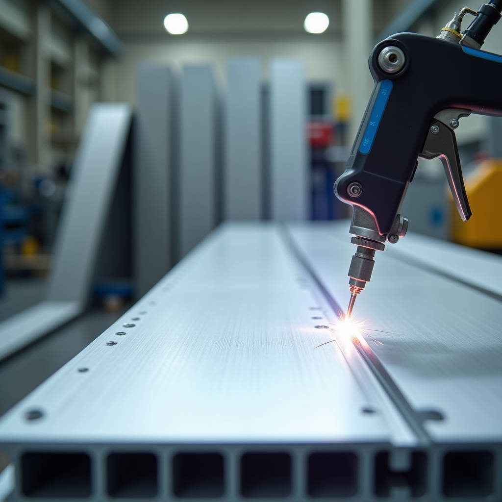
Getting a clean stud weld on solid aluminium cladding panels is not the same game as welding steel. The thermal conductivity of aluminium pulls heat away from the weld zone roughly three times faster than steel does. That speed changes everything about how you set up your equipment, how you prep the surface, and how you qualify the bond. When a facade contractor is dealing with 2.5mm or 3.0mm PVDF-coated solid aluminium panels and needs to attach stiffeners, mounting clips, or sub-frame connectors without drilling through the visible face, Aluminum Panel Stud Welding becomes the only viable path. But the oxide layer on aluminium melts at around 2,000°C while the base metal underneath melts at roughly 660°C. That gap is the root of every failure mode you will encounter in the field.
Why the Oxide Layer Dictates Every Decision
Aluminium forms aluminium oxide (Al₂O₃) the instant bare metal meets air. The layer is only about 4 nanometers thick on freshly cleaned material, but it is electrically insulating and mechanically stubborn. In Aluminum Panel Stud Welding, the arc has to punch through this oxide skin before it can fuse the stud to the base metal. If the oxide remains, you get a cold joint that looks intact but fails under wind load or thermal cycling.
The practical consequence is that surface preparation cannot be treated as a checkbox exercise. Wire brushing with a stainless steel brush dedicated only to aluminium is the minimum. The brushing must happen immediately before welding. If the panel sits for more than 20 minutes after brushing, the oxide reforms enough to compromise weld quality. On a jobsite with 800 panels to process, that timing constraint drives logistics.
Some fabricators try chemical oxide removal using alkaline etchants or acid-based deoxidizers. This works in a controlled shop environment but introduces rinse water management and chemical disposal headaches. For field welding on already-installed panels, mechanical prep is usually the only practical option. Either way, the operator needs to understand that the oxide is not a contaminant you remove once. It is a moving target.
Capacitor Discharge vs. Drawn Arc: Choosing the Right Process for Cladding
Two processes dominate Aluminum Panel Stud Welding: Capacitor Discharge (CD) and Drawn Arc (DA). The choice is not academic. It directly affects whether you burn through a 2.0mm panel or leave a visible mark on the weather side.
CD welding uses a bank of capacitors to dump a high-current pulse lasting 3 to 10 milliseconds. The stud tip has a small ignition tip that vaporizes, creating the arc and fusing the stud to the base. Because the cycle is so short, heat input is minimal. On thin-gauge solid aluminium panels, this is the difference between a clean attachment and a warped face. CD works best for studs up to M8 or 5/16-inch diameter. The bond is strong enough for stiffener attachment and secondary framing, but the weld area is limited to the stud diameter.
Drawn Arc welding, by contrast, uses a longer arc duration, typically 100 to 500 milliseconds. The stud is lifted, an arc is established, and then the stud is plunged into the molten pool. DA produces deeper fusion and handles larger studs, up to M16 or 5/8-inch. But the heat input is significantly higher. On a 2.5mm solid aluminium panel, DA welding without precise parameter control can cause visible distortion on the exposed face. That distortion is unacceptable on Class A architectural finishes under AAMA 2605 standards.
The table below summarizes the key differences for cladding applications:
| Parameter | Capacitor Discharge (CD) | Drawn Arc (DA) |
|---|---|---|
| Weld Duration | 3–10 ms | 100–500 ms |
| Stud Diameter Range | M3–M8 (≈ #4–5/16") | M6–M16 (≈ 1/4–5/8") |
| Minimum Panel Thickness | 1.5mm (with careful setup) | 2.5mm (to avoid burn-through) |
| Risk of Face-Side Distortion | Low | Moderate to High |
| Shielding Gas Required | Not typically (short arc) | Yes (argon or argon-helium mix) |
| Ceramic Ferrules Needed | No | Yes |
| Typical Cladding Application | Stiffener attachment, light clips | Heavy sub-frame brackets, canopy anchors |
For most solid aluminium facade work, CD welding covers 80% of the attachment requirements. The exceptions are large structural brackets and canopy supports where the engineer specifies a larger stud and deeper fusion. In those cases, DA welding with shielding gas and ceramic ferrules is the standard approach, but the operator must dial in parameters on scrap panels before touching production material.
Shielding Gas: What Actually Works on Aluminium
When DA welding aluminium studs, shielding gas is non-negotiable. Aluminium reacts with oxygen and nitrogen in the atmosphere at welding temperatures. Without gas coverage, the molten pool absorbs porosity and forms brittle aluminium nitride inclusions. The result is a weld that snaps under a hammer test.
Pure argon is the baseline shielding gas for Aluminum Panel Stud Welding. It provides a stable arc and adequate coverage. For thicker panels or larger studs, an argon-helium mix (typically 75% Ar / 25% He or 50/50) increases arc energy and improves wetting at the weld interface. Helium raises the arc voltage, which translates to a hotter, more fluid weld pool. The trade-off is cost. Helium is significantly more expensive than argon, and supply chain disruptions have made pricing volatile in recent years.
Flow rate matters as much as gas composition. For stud welding on aluminium panels, 15 to 25 cubic feet per hour (CFH) is the typical range. Too little gas and you get porosity. Too much and you create turbulence that pulls ambient air into the weld zone. The gas nozzle on the stud gun must be sized correctly for the stud diameter and the ferrule geometry. A mismatched setup wastes gas and produces inconsistent results.
On jobsites, wind is the enemy of gas coverage. Welding on an open scaffold at 20 stories up with a 15-knot breeze requires wind screens or a temporary enclosure. Some contractors use gas lenses or diffuser screens inside the gun nozzle to improve coverage in drafty conditions. These are small investments that prevent large-scale rework.
Panel Thickness, Heat Input, and the Distortion Problem
Solid aluminium cladding panels typically range from 2.0mm to 3.0mm for exterior facades. Thicker panels, 4.0mm and above, are used for canopies, column covers, and high-impact zones. The panel thickness directly constrains your stud welding parameters.
Heat input for a stud weld is proportional to the square of the current multiplied by time. For CD welding, the energy stored in the capacitor bank is ½CV², where C is capacitance and V is the charging voltage. A typical CD weld on a 2.5mm aluminium panel might use 1,200 to 2,200 µF at 150 to 200 volts. The exact numbers depend on the stud diameter and the specific alloy.
The problem with thin panels is that heat spreads laterally before it dissipates through the thickness. On a 2.0mm panel, a CD weld that is too hot will create a visible heat-affected zone on the reverse side. If the panel is PVDF-coated, that heat can discolor the coating or cause localized delamination. The 3-coat PVDF systems specified under AAMA 2605 typically withstand continuous service temperatures up to 150°C, but the peak temperature at the weld interface can exceed 600°C momentarily. The coating directly opposite the weld is at risk.
Practical mitigation strategies include:
- Backing bars: A copper or aluminium chill block clamped behind the weld zone acts as a heat sink and reduces peak temperature on the face side.
- Pulse shaping: Some advanced CD power supplies allow the current waveform to be tailored, ramping up more gradually to reduce thermal shock.
- Stud tip design: The geometry of the ignition tip affects arc initiation and heat distribution. Flat-tipped studs with a small projection produce more consistent results on thin aluminium than pointed tips.
- Weld location: Placing studs near panel edges or in corners where the panel is stiffer reduces the visible effect of any distortion.
Fabricators like Futeng® who run high-volume aluminium panel production lines typically develop proprietary parameter sets for each panel thickness and alloy combination. These parameter libraries are built through destructive testing and cross-section analysis, not just visual inspection. When a contractor sources panels from a supplier that also does the stud welding in-house, the process control is inherently tighter than jobsite welding.
Alloy Selection and Its Effect on Weldability
Not all aluminium alloys weld equally well. The 5000-series alloys (Al-Mg) are the most weldable and are the standard for architectural cladding. 5052 and 5754 are common choices. These alloys have good arc stability, low hot-cracking sensitivity, and acceptable strength after welding.
The 3000-series (Al-Mn) alloys, particularly 3003 and 3105, are also used for cladding panels. They weld acceptably but have slightly lower strength than 5000-series. The 6000-series (Al-Mg-Si) alloys, such as 6061, are more challenging. They are prone to hot cracking during stud welding because the magnesium and silicon content creates a wide solidification range. If the project specification calls for 6061 panels, stud welding parameters must be developed specifically for that alloy, and preheating may be required for DA welds.
The 1000-series (commercially pure aluminium) welds easily but has low strength. It is rarely used for exterior cladding except in specialized chemical-resistant applications.
For the project manager writing a specification, the key point is this: if stud welding is planned as the attachment method, the panel alloy must be specified accordingly. Ordering 6061-T6 panels and then discovering on site that they crack during stud welding is an expensive lesson. The alloy and temper should be confirmed with the panel supplier before production begins.
Quality Testing That Actually Predicts Field Performance
Visual inspection of stud welds on aluminium panels is misleading. A weld that looks perfectly formed can have zero fusion at the interface. The standard field test is the hammer test: strike the stud from the side with a calibrated hammer blow and observe whether it bends without fracturing at the weld. But a hammer test is qualitative and operator-dependent.
For critical facade attachments, a more rigorous approach is needed. Torque testing applies a known rotational force to the stud until failure or a specified proof load is reached. A properly welded M6 aluminium stud on a 2.5mm 5052 panel should withstand a torque of at least 8 to 12 Nm before the stud or base material fails. The exact value depends on the stud material and the weld area.
Tensile pull-off testing is the gold standard. A hydraulic pull tester applies an axial load to the stud until failure. The failure mode tells you everything. A ductile fracture in the stud shank means the weld is stronger than the stud. A brittle fracture at the weld interface means the weld is the weak link. For structural attachments, the specification should require that the weld strength exceeds the stud tensile strength, so failure always occurs in the stud, not the weld.
Macro-etch cross-sectioning is done in the lab, not the field, but it is essential for procedure qualification. A cross-section through the weld shows the depth of fusion, the presence of porosity, and the extent of the heat-affected zone. For CD welds on aluminium, fusion depth should be at least 0.3mm across the full stud diameter. For DA welds, the fusion zone should extend into the base metal by at least 0.5mm.
Standards relevant to Aluminum Panel Stud Welding quality include ISO 14555 for arc stud welding of metallic materials and AWS D1.2 for structural welding of aluminium. Contractors working on projects in North America should also be aware of the Aluminum Association's design guidelines for welded aluminium structures.
Common Failure Modes and How to Diagnose Them
When a stud weld fails on an aluminium cladding panel, the root cause is usually one of five things. Diagnosing the failure mode correctly determines whether you adjust parameters, change prep procedures, or reject a batch of studs.
Cold lap (lack of fusion): The stud is attached but there is no metallurgical bond. The arc did not fully melt the base metal surface. Causes include insufficient current, oxide layer not removed, or the stud gun lifting before the weld pool solidified. This is the most common failure in CD welding of aluminium and the hardest to detect visually.
Porosity: Gas bubbles trapped in the weld metal reduce the effective cross-sectional area. On aluminium, porosity is almost always caused by inadequate shielding gas coverage or hydrogen contamination. Hydrogen comes from moisture, oil, or hydrated oxide on the panel surface. Preheating the panel to 60–80°C can drive off moisture and reduce porosity risk.
Burn-through: The weld penetrates completely through the panel, leaving a hole or a visible bump on the face side. This happens when the current is too high for the panel thickness or the arc duration is too long. On PVDF-coated panels, burn-through also damages the coating around the hole, requiring a patch repair that is never invisible.
Hot cracking (solidification cracking): The weld metal cracks as it solidifies due to thermal stresses and alloy chemistry. 6000-series alloys are particularly susceptible. Using a filler metal with a different composition (via the stud material) can mitigate this, but the better solution is to avoid 6000-series panels for stud-welded applications.
Arc blow: The welding arc is deflected by magnetic fields, causing uneven fusion. This is more common in DC welding and can be caused by the workpiece geometry, the grounding clamp position, or residual magnetism in fixturing. Moving the ground clamp or using AC welding (where available) can resolve arc blow.
Equipment Selection: What to Look for in a Stud Welder for Aluminium
The stud welding equipment market is broad, but machines optimized for aluminium share specific characteristics. A CD stud welder for aluminium panels should have adjustable voltage in fine increments, typically 5-volt steps or better, and capacitance that can be switched in banks to match the stud diameter and panel thickness.
Key equipment features for aluminium include:
- Lift-and-drop mechanism: The gun must lift the stud to establish the arc and then plunge it with controlled force. Spring pressure and lift height must be adjustable. Aluminium requires a softer plunge than steel because the molten pool is more fluid.
- Ignition tip detection: Some machines sense whether the stud has an ignition tip and adjust the arc initiation accordingly. This prevents misfires when a tip is missing or damaged.
- Grounding system: The ground clamp must make low-resistance contact with the aluminium panel. Aluminium oxide is an insulator, so the clamp must bite through the oxide layer. Serrated copper contacts or spring-loaded pins are effective.
- Gas control integration: For DA welding, the machine should control gas pre-flow and post-flow timing. Pre-flow purges air from the weld zone before the arc strikes. Post-flow protects the solidifying weld from oxidation.
Portable CD stud welders weighing under 20 kg are practical for jobsite use. Larger DA systems with separate power supplies and gas controls are better suited to shop fabrication where the environment is controlled. The American Welding Society publishes equipment selection guidelines that are useful for specifying stud welding systems for aluminium fabrication.
Integrating Stud Welding into the Panel Fabrication Workflow
For a fabrication shop producing solid aluminium cladding panels, stud welding is not a standalone process. It sits between panel cutting and forming and the surface finishing stage. The sequence matters because welding after coating destroys the finish, and coating after welding requires that the welded assembly fits in the coating line.
A typical workflow looks like this:
- Panel blank is cut to size and formed (bending, folding, routing).
- Stiffener locations are marked on the reverse side based on engineering drawings.
- Studs are welded at marked positions using CD or DA process as specified.
- Welds are visually inspected and tested per the quality plan.
- Panel proceeds to surface treatment: chromate conversion coating, primer, PVDF topcoat.
- After coating, stiffeners and brackets are attached to the welded studs using mechanical fasteners or adhesive.
The critical constraint is that the welded studs must survive the pretreatment and coating process without corrosion or contamination. Chromate conversion coating baths can attack poorly fused welds. If the stud material is a different alloy from the panel, galvanic corrosion can initiate at the weld interface during wet processing. Specifying studs made from the same or a compatible alloy (e.g., 5356 or 4043 aluminium studs for 5052 panels) eliminates this risk.
For projects where panels are coated before stud welding, the coating must be locally removed at each weld location. This adds labor and creates a corrosion protection gap that must be addressed after welding. The AAMA finishing guidelines provide recommendations for touch-up procedures on welded aluminium assemblies.
Wind Load, Structural Capacity, and Stud Spacing
The engineering reason for using stud welding on aluminium cladding panels is to transfer wind loads from the panel face to the sub-frame without visible fasteners. The studs become the load path. Getting the stud spacing and capacity right is a structural engineering problem, not just a welding problem.
Wind loads on building facades are calculated per ASCE 7 in the United States, EN 1991-1-4 in Europe, or the local building code equivalent. A typical design wind pressure for a mid-rise building in a suburban area might be 1.5 to 2.5 kPa (31 to 52 psf). The panel area tributary to each stud determines the load per stud. For a 1.2m × 2.4m panel with four studs, each stud carries roughly 0.72 m² of wind area, or about 1.1 to 1.8 kN per stud at the design pressures above.
A properly executed CD weld on a 2.5mm 5052 aluminium panel with an M6 aluminium stud typically achieves a tensile strength of 2.5 to 4.0 kN. That provides a safety factor of roughly 2.0 to 3.5 against the design wind load, which is acceptable for most facade applications. However, the safety factor must account for fatigue from cyclic wind loading, thermal expansion stresses, and potential degradation over the building's service life.
Stud spacing is also governed by panel deflection limits. Even if the studs are strong enough, the panel between studs must not deflect excessively under wind load. For solid aluminium panels, deflection is typically limited to L/175 or L/240 of the span between stiffeners, depending on the project specification. This often controls stud spacing more than the stud capacity does.
Thermal Movement and Long-Term Durability
Aluminium expands and contracts with temperature changes at a rate of roughly 23 × 10⁻⁶ per °C. A 3-meter panel subjected to a 60°C temperature swing (from -10°C in winter to 50°C in direct summer sun) changes length by about 4.1mm. If the studs rigidly fix the panel to the sub-frame, that movement has to go somewhere.
The solution is to design the attachment system so that some studs provide fixed points while others allow sliding. A common approach is to use slotted holes in the stiffeners or brackets that attach to the welded studs. The fixed studs resist wind loads in all directions. The sliding studs resist loads perpendicular to the panel face but allow in-plane movement.
Over decades of service, the stud welds themselves are subject to fatigue from thermal cycling and wind-induced vibration. Aluminium has no fatigue limit, meaning it will eventually fail under cyclic loading even at low stress levels. For a building facade with a 50-year design life, the stress range in the stud welds under cyclic loading should be kept below 40 to 50 MPa to achieve acceptable fatigue life. This is a detail that separates competent facade engineering from guesswork.
The ISO 14555 standard for stud welding includes provisions for fatigue assessment of welded joints, and the Aluminum Association's fatigue design rules provide S-N curves for welded aluminium connections.
Practical Field Recommendations
After years of troubleshooting stud welding problems on aluminium cladding projects, a few recommendations stand out. First, qualify the welding procedure on the exact panel material that will be used on the project. The same alloy from a different mill can behave differently. Second, invest in operator training. Aluminum Panel Stud Welding is not a skill picked up in an afternoon. The difference between a trained operator and an untrained one is the difference between a facade that passes inspection and one that requires months of rework. Third, do not skip the destructive testing. Pull a sample of studs to failure at the start of each shift and whenever parameters change. The cost of testing is trivial compared to the cost of replacing panels after installation. Fourth, document everything. Weld parameters, operator names, test results, and environmental conditions should be recorded for every batch of panels. When a problem surfaces five years later, that documentation is what separates a manageable warranty claim from a legal dispute.
For contractors sourcing panels from overseas fabricators, verifying the stud welding quality control process at the factory is as important as checking the PVDF coating thickness. A factory audit that includes weld procedure review, cross-section samples, and pull-test data provides confidence that the panels arriving on site will perform as specified. Fabricators who take Aluminum Panel Stud Welding seriously will have this data ready to share.