Aluminum Panel MIG Welding for Solid Architectural Cladding Distortion Control and Coating Compatibility
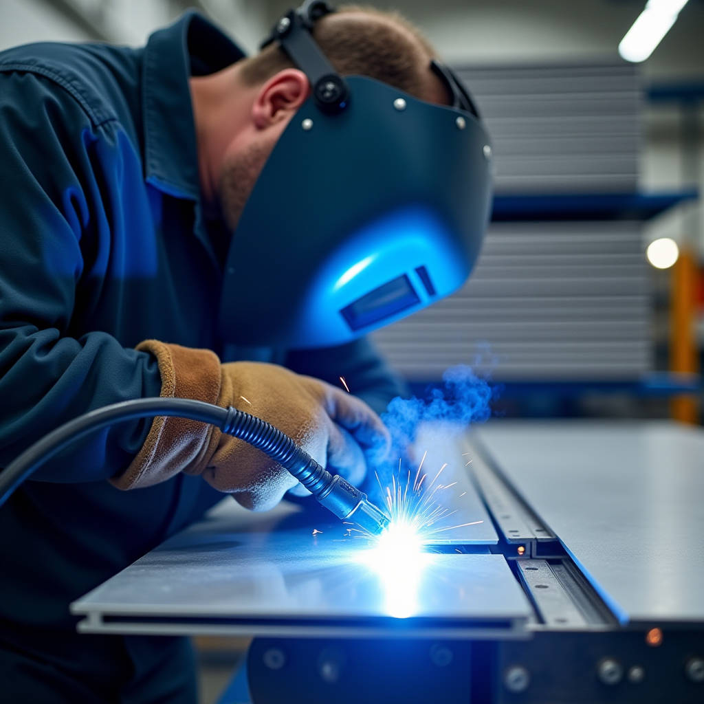
Aluminum Panel MIG Welding on solid cladding panels demands a fundamentally different approach than what most fabricators expect from general aluminum welding. When you are joining 2.0mm, 2.5mm, or 3.0mm solid aluminium sheets for architectural facades, the stakes are not just structural integrity — the weld zone must remain flat enough to accept PVDF or FEVE coating without telegraphing through the finish, and the heat-affected zone must not compromise the panel's flatness tolerance across spans that can exceed 1,200mm. This article strips away generic welding advice and focuses on what actually matters for architectural cladding fabrication: controlling distortion on thin-gauge panels, selecting filler alloys that match your coating system, and setting up production workflows that deliver repeatable results when you are running hundreds of panels per project.
Why Solid Aluminium Cladding Panels Present Unique Welding Challenges
Solid aluminium cladding panels — typically 1100, 3003, or 5052 series alloys — behave very differently under the arc compared to the 6061 structural extrusions that most welding guides address. The thermal conductivity of these alloys pulls heat away from the weld zone almost as fast as you can put it in, which means you need higher travel speeds and tighter parameter control than you would use on thicker structural sections.
The real problem, however, is distortion. A 2.5mm-thick panel measuring 1,500mm by 1,000mm has very little inherent stiffness. When you run a MIG bead along an edge or corner joint, the localized heating causes the panel to bow. Once that bow exceeds 0.5% of the panel's diagonal dimension — roughly 9mm on a 1,800mm diagonal — the panel fails AAMA flatness requirements for architectural cladding. Getting the weld done without exceeding this threshold is where most shops struggle.
Three factors determine whether you stay within tolerance: heat input per unit length, the sequence in which you weld multiple joints, and how you fixture the panel during and after welding. Shops that treat Aluminum Panel MIG Welding as a simple extension of steel fabrication inevitably produce panels that look fine on the welding bench but fail inspection once mounted on the building.
Alloy Selection for Architectural Cladding: 1100, 3003, and 5052
Before touching the torch, you need to know exactly what you are welding. The three most common solid aluminium cladding alloys each demand specific filler choices:
1100-H14: Commercially pure aluminium with excellent corrosion resistance and formability. Used extensively in roofing and wall cladding where structural loads are minimal. When MIG welding 1100 panels, ER1100 filler provides the closest color match after anodizing, but for PVDF-coated panels, ER4043 is often preferred because its silicon content reduces the solidification cracking risk that pure aluminium is prone to.
3003-H14: Manganese-alloyed aluminium with roughly 20% higher strength than 1100. This is the workhorse of the architectural cladding industry. It welds cleanly with ER4043 filler, and the resulting weld zone accepts PVDF primer and topcoat without the discoloration issues that sometimes plague 5052 welds. For most curtain wall and rainscreen applications, 3003 with ER4043 represents the optimal balance of cost, weldability, and coating compatibility.
5052-H32: Magnesium-alloyed aluminium with significantly higher strength and excellent corrosion resistance in marine environments. When welding 5052 panels, ER5356 filler is the standard choice because it matches the base metal's magnesium content and maintains the corrosion resistance. However, ER5356 welds can show slight darkening under certain PVDF colors, particularly whites and light metallics. This is rarely a structural concern but matters enormously when the architect is standing on the lift inspecting panel joints at close range.
| Panel Alloy | Recommended Filler | Typical Tensile Strength (Welded Joint) | PVDF Coating Compatibility | Best Application |
|---|---|---|---|---|
| 1100-H14 | ER4043 or ER1100 | 70-90 MPa | Excellent with ER4043 | Interior cladding, soffits, low-load facades |
| 3003-H14 | ER4043 | 95-110 MPa | Excellent — industry standard | Curtain wall panels, rainscreens, general architectural |
| 5052-H32 | ER5356 | 170-190 MPa | Good — slight risk of weld line visibility | Marine environments, high-wind zones, structural panels |
Wire Feeding: The Bottleneck That Determines Productivity
Aluminium wire is soft. A 1.2mm ER4043 wire will birds-nest at the drive rollers if you look at it wrong. This is not a minor inconvenience — it is the single biggest productivity killer in production Aluminum Panel MIG Welding. Every time the wire tangles inside the machine, you lose 5-10 minutes clearing the jam, and the panel sitting half-welded on your bench is cooling unevenly, potentially locking in distortion.
The solution set is well-established but frequently ignored by shops trying to save money:
- Spool gun: Mounts a small wire spool directly on the gun, reducing the feed distance to roughly 200mm. This eliminates 90% of feeding problems and is the minimum viable setup for any shop doing more than occasional aluminium work. The trade-off is ergonomics — spool guns are heavier and bulkier than standard MIG guns.
- Push-pull system: A motor in the gun pulls while the drive unit pushes. Feed distances of 8 meters or more become practical. For a cladding fabricator running multiple welding stations, a centralized push-pull system with bulk wire drums dramatically reduces downtime.
- U-groove drive rolls: Whether you run a spool gun or push-pull, standard V-groove rolls will deform aluminium wire. U-groove rolls provide the necessary grip without crushing the wire cross-section.
- Teflon or nylon liners: Standard steel liners create friction that aluminium wire cannot tolerate. A full-length Teflon liner from the drive unit to the contact tip is non-negotiable.
Fabricators sourcing panels from manufacturers like Futeng® often specify that shop-welded corner joints and stiffener attachments be performed with push-pull equipment to maintain the panel's flatness certification. The equipment investment pays back within the first project that does not require rework.
Parameter Settings: What Actually Works on Thin-Gauge Cladding Panels
Generic aluminium MIG charts typically assume you are welding 3mm or thicker material. On a 2.0mm solid aluminium cladding panel, those settings will blow through in under a second. The following parameters are derived from production experience on 3003-H14 panels using 1.2mm ER4043 wire and 100% argon shielding gas at 15-18 L/min flow rate:
| Panel Thickness | Wire Feed Speed | Voltage | Travel Speed (Approx.) | Joint Type | Notes |
|---|---|---|---|---|---|
| 2.0mm | 4.5-5.5 m/min | 16-18 V | 600-750 mm/min | Outside corner, butt | Use 0.8-1.0mm wire if available for better low-end control |
| 2.5mm | 5.5-6.5 m/min | 17-19 V | 500-650 mm/min | Outside corner, lap, butt | Standard starting point for most cladding work |
| 3.0mm | 6.5-7.5 m/min | 18-21 V | 400-550 mm/min | All joint types | Pulse MIG significantly improves bead appearance and reduces spatter |
These numbers are starting points. Ambient temperature, humidity, and the specific alloy batch all shift the sweet spot. The non-negotiable rule is to test on scrap from the same material lot as your production panels, not on a random offcut that has been sitting on the rack for six months.
Pulse MIG: When It Is Worth the Extra Cost
Pulse MIG alternates between a high-current pulse that transfers one droplet of filler and a low-current background that maintains the arc without transferring metal. For Aluminum Panel MIG Welding on cladding, the benefits are concrete:
- Lower average heat input reduces distortion on thin panels
- Spatter is virtually eliminated — critical because spatter particles create pinhole defects in PVDF coating
- The pulsed arc provides a cleaning action that helps break up the aluminium oxide layer
The cost premium for a pulse-capable machine is significant — typically 40-60% more than a standard MIG power source. For a fabricator producing 50 panels per week, the payback period through reduced rework and faster post-weld cleaning is typically 8-14 months. For shops running 200+ panels per week, pulse is not a luxury; it is the only way to maintain consistent quality at volume.
Pre-Weld Preparation: The Oxide Problem
Aluminium oxide melts at approximately 2,050°C. The aluminium underneath melts at roughly 660°C. If you do not remove the oxide layer before welding, the arc will melt the base metal while chunks of oxide float around in the weld pool, creating inclusions that weaken the joint and create visible defects in the finished panel.
The preparation sequence for architectural cladding panels is specific:
- Degrease: Use acetone or a dedicated aluminium cleaner to remove mill oils, forming lubricants, and handling residue. Do not use brake cleaner or chlorinated solvents — they decompose under the arc and produce toxic gases.
- Mechanical oxide removal: A stainless steel wire brush used exclusively for aluminium (never cross-contaminated with steel) is the standard tool. Brush in one direction only; scrubbing back and forth can embed oxide particles into the surface.
- Weld within 2 hours: Aluminium oxide begins reforming immediately. The window between cleaning and welding is short — 2 hours maximum in a climate-controlled shop, less in humid conditions.
For panels that will receive PVDF coating, an additional step is critical: the weld zone must be sanded smooth with 120-180 grit abrasive to remove any surface irregularities before the panel goes to the coating line. A weld bead that looks perfectly acceptable in the raw state can telegraph through a 30-micron primer and 25-micron color coat as a visible ripple.
Distortion Control: Fixturing and Sequence Strategies
Distortion in Aluminum Panel MIG Welding is not something you fix after the fact — it is something you prevent through fixturing and weld sequence planning. Once a panel has bowed, straightening it without damaging the surface finish is extremely difficult and often impossible to do within the flatness tolerances required by AAMA 609 and 610 standards.
Backing bars: A copper or aluminium backing bar clamped behind the weld joint serves two purposes. It acts as a heat sink, pulling excess heat out of the panel and reducing the size of the heat-affected zone. It also provides a surface for the weld pool to form against, which is particularly useful on outside corner joints where the edge of a 2.0mm panel offers very little material to support the bead.
Tack welding sequence: For a rectangular panel with corner joints, the sequence matters enormously. Weld one corner, then move to the diagonally opposite corner. This balances the thermal stresses. If you weld adjacent corners sequentially, the panel will bow toward the side that was welded first.
Staggered welding: On long joints — such as attaching a stiffener channel to the back of a panel — weld in 50-75mm segments with 100mm gaps, then come back and fill the gaps. This allows each segment to cool before the adjacent area is heated, reducing the cumulative distortion.
Post-weld restraint: Leave the panel clamped in the fixture until it has cooled to below 50°C. Releasing a panel while it is still hot from welding is a guaranteed way to produce a banana-shaped part.
Shielding Gas: Why 100% Argon Is the Only Correct Answer
There is no debate here. Argon-helium mixtures have their place in heavy-section aluminium welding where deeper penetration is needed, but for thin-gauge cladding panels, 100% argon is the standard. Argon-CO₂ mixes — commonly used for steel — will contaminate the aluminium weld with carbon, producing a black, sooty deposit and a brittle joint.
Gas flow rate matters more than most welders realize. Too little flow and atmospheric contamination produces porosity. Too much flow creates turbulence that draws air into the shielding envelope. For the nozzle sizes typically used on cladding panel work (12-16mm diameter), 15-18 liters per minute is the sweet spot. A gas lens can improve coverage at the lower end of this range, which is useful when welding in drafty shop conditions.
Pre-flow and post-flow settings are often overlooked. A 0.5-second pre-flow ensures the shielding envelope is established before the arc strikes. Post-flow of 1-2 seconds protects the cooling weld bead and prevents crater oxidation. On a 3.0mm panel corner joint, insufficient post-flow will leave a grey, oxidized crater that must be ground out before coating.
Common Defects in Cladding Panel Welds and Their Root Causes
When you inspect a welded panel before it goes to coating, certain defects are immediate red flags. Others are subtle but will cause problems once the panel is on the building.
Crater cracking: The most common defect in aluminium MIG welding. When the arc extinguishes, the weld pool solidifies from the outside in, and the last liquid metal in the center of the crater shrinks and tears. The fix is straightforward: use the welder's crater-fill function if available, or manually back-step the torch at the end of each weld to fill the crater.
Porosity: Hydrogen gas bubbles trapped in the solidifying weld. Sources include moisture on the panel surface, hydrocarbon contamination, or insufficient shielding gas coverage. In cladding applications, porosity is particularly problematic because the bubbles can be just below the surface and become exposed when the weld bead is sanded smooth for coating.
Lack of fusion: The weld metal sits on top of the base metal without actually bonding. On thin panels, this often happens when the welder reduces heat input to avoid burn-through but goes too far. The joint looks complete but fails under the first thermal cycle — which, on a building facade, happens every day the sun hits the panel.
Excessive reinforcement: A weld bead that stands too proud of the panel surface. For architectural cladding, the reinforcement should not exceed 1.5mm above the base metal. Anything taller will be visible after coating and may interfere with panel joint alignment on the building.
Production Workflow: From Sheet to Finished Panel
Integrating Aluminum Panel MIG Welding into a cladding fabrication line requires thinking about the entire workflow, not just the welding step. The following sequence has proven effective in shops producing 100-500 panels per week:
- CNC routing and forming: Panels are cut to size, edge returns are formed, and any cutouts for windows or louvers are machined. The edges to be welded should be left with a clean, square cut — no burrs or rolled edges.
- Pre-weld cleaning: Dedicated cleaning station with acetone, stainless brushes, and lint-free wipes. Panels move directly from cleaning to the welding station.
- Welding: Corner joints, stiffener attachments, and any reinforcement brackets are welded. Each welder should have a defined sequence for each panel type, documented with photos and posted at the station.
- Post-weld inspection: Check flatness against a granite surface plate or laser measurement system. Check weld bead profile with a gauge. Any panel outside tolerance goes to rework immediately — do not send it to coating hoping it will be "good enough."
- Weld dressing: Sand weld beads flush where required for coating. This is typically done with a 120-grit flap disc followed by a 180-grit finish.
- Pre-treatment and coating: The panel goes through chromate conversion coating or an equivalent pre-treatment before PVDF or FEVE liquid coating is applied.
Industry reference: The Aluminum Association publishes detailed guidelines on welding aluminium alloys for architectural applications, and the American Welding Society AWS D1.2 Structural Welding Code — Aluminum provides the governing standard for weld quality acceptance criteria.
Quality Control: What to Check Before the Panel Leaves the Shop
A welded cladding panel that passes visual inspection in the shop can still fail on site. The following QC checks should be mandatory for every panel in a production run:
Flatness measurement: Place the panel on a certified flat inspection table. Measure the gap between the panel surface and the table at the point of maximum deviation. For panels up to 1,200mm diagonal, the gap should not exceed 2mm. For larger panels, consult the project specification, but 0.5% of diagonal is a common benchmark.
Weld bead visual inspection: Under adequate lighting, check for cracks, porosity, undercut, and overlap. A 10x magnifier is useful for spotting hairline crater cracks that the naked eye misses.
Dye penetrant testing: For critical joints — particularly on panels that will be installed at height or in high-wind zones — dye penetrant inspection provides a quick, low-cost check for surface-breaking defects. The ASTM E1417 standard governs the procedure.
Coating adhesion test: After the panel returns from coating, perform a cross-hatch adhesion test per ASTM D3359 on the weld zone. The coating must achieve the same adhesion rating on the weld as on the base metal. If it does not, the weld preparation or filler alloy selection needs to be revisited.
When to Weld vs. When to Use Mechanical Fastening
Not every aluminium cladding panel joint needs to be welded. The decision between welding and mechanical fastening — rivets, clinching, or structural adhesive — should be based on engineering requirements, not shop habit.
Weld when: The joint is visible on the exterior and must present a seamless appearance after coating. The panel requires a continuous water barrier at the joint. The structural load path requires the full strength of the base metal at the connection.
Use mechanical fastening when: The joint is hidden behind the panel and will never be seen. The panel needs to accommodate thermal movement, which a welded joint will restrain. The production volume is high enough that the speed advantage of mechanical fastening outweighs the aesthetic benefit of welding.
On a typical rainscreen panel, the visible corner joints are welded and dressed smooth, while the stiffener channels on the back are attached with stainless steel blind rivets or structural adhesive. This hybrid approach balances aesthetics with production efficiency.
Aluminum Panel MIG Welding on solid cladding panels is a specialized skill that sits at the intersection of welding technology, architectural finishing, and production engineering. The shops that do it well are not the ones with the most expensive machines — they are the ones that have thought through the entire process from sheet metal to finished panel, documented their procedures, and trained their welders to understand why each step matters. When the panel goes up on the building and the coating is flawless from edge to edge, the effort that went into controlling distortion, selecting the right filler, and dressing the weld beads becomes invisible. That invisibility is the whole point.