Aluminum Panel TIG Welding for Solid Cladding Joint Design Alloy Matching and Coating Integrity
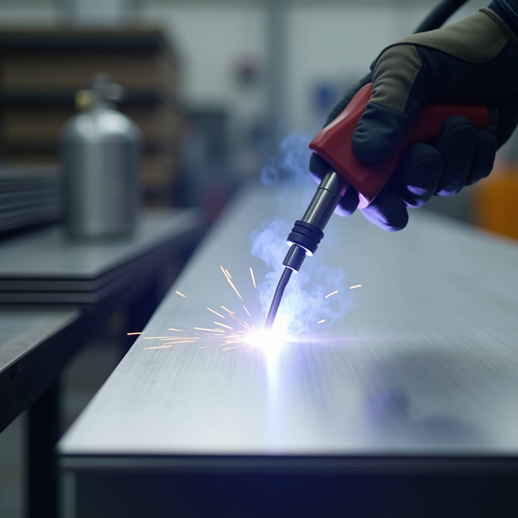
When a cladding contractor calls about a failed corner joint on a 3.0mm solid aluminium panel, the conversation rarely starts with metallurgy. It starts with water ingress, a visible crack, or a panel that pulled loose during a windstorm. The root cause, more often than anyone wants to admit, traces back to the weld. Aluminum Panel TIG Welding is not a generic fabrication step you can hand off to any welder with an AC machine and a stack of 4043 filler rods. Solid aluminium cladding panels behave differently than extruded profiles, cast components, or thin-gauge sheet metal. The thermal mass, the alloy temper, the PVDF coating proximity, and the service environment all conspire to punish shortcuts. This article digs into what actually fails on architectural TIG welds, why standard shop practices fall short, and how to engineer joints that stay sealed and structurally sound across decades of thermal cycling and moisture exposure.
Why Solid Aluminium Cladding Panels Demand a Different Welding Mindset
Most TIG welding knowledge circulating in workshops and online forums comes from automotive, marine, or general fabrication contexts. A 5052-H32 solid aluminium panel at 2.5mm or 3.0mm thickness sits in a different category entirely. These panels arrive with a factory-applied PVDF or FEVE coating system, typically 25-35 microns of primer plus 25-30 microns of color coat, baked at precisely controlled temperatures. The coating is not just decorative. It is the primary weather barrier for a building envelope expected to perform for 30-plus years.
The problem starts when welding occurs too close to coated surfaces. PVDF resin systems begin degrading at sustained temperatures above 240°C. A TIG arc generates a heat-affected zone (HAZ) that can easily push 300°C to 400°C at distances of 15-20mm from the weld pool. This means the coating edge adjacent to any welded attachment point may already be compromised before the panel leaves the fabrication shop. The damage is rarely visible. It shows up three years later as delamination, chalking, or filiform corrosion creeping outward from the weld zone.
Another factor: 5052 aluminum, the workhorse alloy for architectural cladding, contains roughly 2.5% magnesium and 0.25% chromium. This alloy strain-hardens to H32 temper, giving it a tensile strength around 230 MPa. When you TIG weld it, you locally anneal the material. The HAZ drops back toward the annealed condition, roughly 170-190 MPa tensile. On a structural attachment point carrying wind load, that strength reduction matters. Engineers who specify "weld all around" on a stiffener bracket without accounting for the HAZ softening are designing a joint that may be 25% weaker than the base metal they assumed in calculations.
Alloy Selection and Filler Rod Matching for Architectural Applications
Walk into most fabrication shops and you will find spools of 4043 filler rod. It flows nicely, wets out smoothly, and forgives minor contamination better than 5356. For architectural cladding, 4043 is often the wrong call. Here is why.
4043 filler contains approximately 5% silicon. When welded to 5052 base metal, the resulting weld pool chemistry shifts. The silicon-rich weld metal has lower ductility and a different electrochemical potential than the surrounding 5052 panel. In a coastal or industrial environment where the panel sees salt spray or acid rain, this galvanic mismatch accelerates corrosion at the weld toe. The weld itself may remain intact, but the base metal immediately adjacent begins pitting.
5356 filler rod, with roughly 5% magnesium, matches the 5052 chemistry far more closely. The weld metal and base metal share similar corrosion potentials. Ductility remains higher. For any solid aluminium cladding panel that will face exterior exposure, 5356 should be the default filler choice unless the project specification explicitly requires something else. The trade-off: 5356 welds slightly less fluid than 4043, demanding tighter arc control and cleaner joint preparation. That trade-off is worth making.
For panels fabricated from 3003 or 5005 alloys, 4043 may be acceptable, but the project engineer should confirm the electrochemical compatibility based on the specific service environment. The Aluminum Association publishes detailed galvanic compatibility data that should inform filler selection on any project exceeding 5,000 square meters of cladding.
| Filler Alloy | Best Base Metal Match | Corrosion Resistance (Exterior) | Ductility | Typical Cladding Application |
|---|---|---|---|---|
| ER4043 | 3003, 5005, 6061 | Moderate — risk of galvanic mismatch with 5052 | Lower | Interior panels, dry climates |
| ER5356 | 5052, 5083, 5454 | High — closely matches 5052 potential | Higher | Exterior cladding, coastal zones |
| ER5183 | 5083, high-Mg alloys | Very high | Highest | Marine-grade architectural |
| ER5556 | 5083, 5456 | Very high | High | Structural attachments, high-stress joints |
AC Balance, Frequency, and the Oxide Problem on Coated Panels
Aluminum forms aluminum oxide within seconds of being exposed to air. That oxide layer melts at roughly 2,050°C, while the base aluminum underneath melts at about 660°C. AC TIG welding solves this by alternating between electrode-positive (EP) cycles that blast through the oxide and electrode-negative (EN) cycles that deliver penetration heat.
The AC balance control determines the ratio of EN to EP time. A setting of 70% EN and 30% EP is a common starting point. On solid aluminium cladding panels, pushing EN higher — toward 75% or even 80% — can improve penetration on thicker 3.0mm material and reduce the heat-affected zone width. The trade-off: less oxide cleaning action. If the panel surface has any residual contamination from handling, cutting lubricants, or coating edge residue, reducing EP time below 25% may leave oxide inclusions in the weld.
AC frequency matters more than many welders realize. Standard 60 Hz works. Increasing to 100-150 Hz tightens the arc cone, narrows the weld bead, and concentrates heat input. On a stiffener-to-panel fillet weld where the stiffener is 2.0mm and the panel is 3.0mm, higher frequency helps direct heat into the thicker panel while minimizing burn-through risk on the thinner stiffener. For panels with complex stiffener geometries, 120 Hz is a practical sweet spot.
One field observation: panels that have been stored outdoors or in humid conditions before welding develop a thicker, more tenacious oxide layer. A welder accustomed to welding fresh, clean sheet may struggle with the same settings on stock that has sat for weeks. The AC balance may need to shift toward 65/35 EN/EP to compensate, and travel speed may need to drop slightly. This is not a machine problem. It is a material condition problem that good shops manage through inventory rotation and climate-controlled storage.
Joint Design for Cladding Panel Stiffener Attachments
The most common TIG-welded joint on an aluminium cladding panel is the stiffener attachment. A formed aluminum stiffener — typically a hat section, Z-section, or angle — is welded to the back face of the panel to increase rigidity and provide attachment points for the curtain wall subframe. The panel face is visible. The stiffener is hidden. The weld is out of sight but not out of consequence.
Intermittent stitch welding is standard practice. A 25mm weld, a 75mm gap, another 25mm weld, repeating along the stiffener length. This pattern reduces heat input, minimizes panel distortion, and allows for thermal movement. The catch: the start and end of each stitch are the weakest points. Craters, cold starts, and abrupt terminations concentrate stress. On a building facade that cycles between -10°C and 50°C across seasons, those stress concentrations drive fatigue cracking.
A better approach: specify a 5mm run-on and run-off tab at each stitch end, to be ground flush after welding. This moves the crater defect outside the structural weld length. It adds labor, but on a high-rise where a failed stiffener means a dangling panel 80 meters above a pedestrian plaza, the labor is justified.
For panels exceeding 1,200mm in any dimension, consider continuous intermittent patterns staggered on opposite sides of the stiffener rather than aligned. This distributes thermal distortion more evenly and reduces the visible "quilting" effect that can telegraph through to the panel face under certain lighting conditions.
Pre-Weld Cleaning: What Actually Works on Architectural Aluminum
Every TIG welding guide emphasizes cleaning. Few specify what cleaning means for PVDF-coated architectural panels. The back face of a solid aluminium cladding panel is typically a wash coat or service coat — a thin, non-architectural coating applied for corrosion protection during storage and transport. This coating must be removed from the weld zone before striking an arc. Acetone wipe alone is insufficient.
The effective sequence:
- Mechanically remove the service coat from the weld zone using a dedicated stainless steel wire brush used only for aluminum. A brush contaminated with steel particles will embed iron in the aluminum surface, guaranteeing pitting corrosion later.
- Wipe the area with acetone or isopropyl alcohol using a clean, lint-free cloth. Do not use shop rags that may carry oil residue.
- Allow the solvent to fully evaporate before welding. Residual solvent in a joint can vaporize and create porosity.
- If the panel has been handled extensively, a final pass with a clean stainless brush immediately before welding removes the oxide layer that reforms within minutes.
One point worth stressing: do not use chlorinated solvents. Brake cleaner and similar products can decompose under the arc's ultraviolet radiation to produce phosgene gas. This is a serious health hazard. The American Welding Society publishes safety guidelines that every fabrication shop should have posted.
Tungsten Selection and Gas Coverage for Consistent Results
For Aluminum Panel TIG Welding on 2.0mm to 3.0mm solid sheets, 2% lanthanated tungsten in 2.4mm (3/32") diameter handles most applications. The lanthanated formulation maintains a stable arc at both low and high amperage, resists splitting, and works well across the AC balance range. Pure tungsten, once the standard for aluminum, has largely been superseded and offers no advantage on architectural work.
Gas coverage deserves more attention than it typically gets. Pure argon at 10-15 L/min (20-30 CFH) through a gas lens setup provides adequate coverage for bench welding. For on-site repair welding where drafts are unavoidable, increase flow to 15-18 L/min and use a larger cup — size 8 or 10 — to maintain the gas envelope. A trailing shield may be necessary for critical cosmetic welds on visible panel edges.
Pre-flow of 0.5-1.0 seconds ensures the tungsten and weld zone are blanketed before the arc initiates. Post-flow of 5-8 seconds protects the cooling weld pool and tungsten from oxidation. Shortening post-flow to save argon is false economy. Oxidized tungsten erodes faster, arc stability degrades, and the resulting weld quality decline costs far more than the gas saved.
Heat Management and Distortion Control on Large-Format Panels
A 1,500mm by 3,000mm solid aluminium panel at 3.0mm thickness represents a large heat sink. It also represents a large canvas for thermal distortion. Aluminum's thermal expansion coefficient is roughly twice that of steel. A weld bead that seems flat and acceptable while hot can pull the panel into a visible wave pattern as it cools.
Several strategies reduce distortion:
- Back-step welding: Each stitch is welded in the opposite direction of the overall weld progression. This staggers the thermal contraction forces and reduces cumulative distortion.
- Heat sinks: Copper or aluminum backing bars clamped behind the weld zone draw heat away from the panel. Copper is preferred for its higher thermal conductivity. The bar must be clean and free of contamination.
- Skip sequence: On a stiffener with six stitch welds, weld stitches 1, 3, 5, then return for 2, 4, 6. This distributes heat input across the panel rather than concentrating it sequentially.
- Clamping strategy: Clamp the panel to a flat steel table, but allow for thermal expansion. Over-constraining a panel during welding builds residual stress that releases as distortion when clamps are removed.
For panels that will receive a post-weld touch-up coating, the distortion tolerance is tighter. A panel with 2mm of wave across its face may still be structurally sound, but the architect will reject it when the raking light hits the facade at 7:00 AM. Shops that invest in proper fixturing and sequenced welding procedures see significantly lower rejection rates.
Post-Weld Inspection and Coating Repair Protocols
A TIG weld on a cladding panel is not finished when the arc extinguishes. The weld must be visually inspected for cracks, craters, undercut, and porosity. A 10x magnifying loupe reveals defects invisible to the naked eye. Any crack, regardless of size, requires grinding out and re-welding. Porosity exceeding 1mm diameter or clustered within 25mm of weld length should trigger rejection.
Dye penetrant testing provides additional confidence for critical structural attachments. A ASTM E1417 compliant penetrant test takes minutes per weld and catches surface-breaking defects that visual inspection misses.
The coating repair around the weld zone is equally important. The heat-affected zone has burned off the factory coating. The exposed aluminum will oxidize and, depending on the environment, begin corroding. A two-part epoxy primer applied to the weld zone and surrounding HAZ, followed by a compatible PVDF touch-up coating, restores the weather barrier. The repair coating system should match the original specification: typically an epoxy or chromate-free conversion primer at 15-25 microns, followed by a PVDF color coat at 25-30 microns.
For projects where the weld zone will remain hidden behind the panel, the primer alone may suffice. For any weld within 50mm of a visible panel edge, the full coating system should be applied and the color match verified under natural daylight. Metamerism — where colors match under shop lighting but diverge in sunlight — is a common source of field disputes.
When Shop Welding Meets Field Reality
Ideally, all TIG welding on aluminium cladding panels happens in a controlled shop environment. In practice, field modifications and repairs are inevitable. A panel arrives on site and does not fit. A penetration needs relocation. A stiffener interferes with a bracket. The site welder unpacks a portable TIG machine and gets to work.
Field conditions undermine every variable that shop welding controls. Wind disrupts gas coverage. Dirt and dust contaminate the weld zone. Access restrictions force awkward torch angles. The panel is already installed, so heat sinking is limited. The result is often a weld that would fail shop inspection but gets accepted because the alternative — removing and replacing the panel — costs too much time and money.
Mitigation measures for field welding include portable wind shields, gas lenses with larger cups, and strict cleaning protocols even when the site superintendent is pushing for speed. A battery-powered stainless brush and a sealed container of acetone should be in the field welder's kit. The project specification should explicitly address field welding procedures, acceptance criteria, and coating repair requirements. Leaving these details to the site team's discretion invites problems.
Futeng® has supplied solid aluminium cladding panels to projects across Southeast Asia and the Middle East where field modifications were anticipated in the contract. The approach that worked: ship extra panels with pre-applied primer in the anticipated modification zones, include a detailed field welding procedure document, and provide touch-up coating kits matched to the factory finish. The incremental cost was minimal compared to the cost of rework and delay claims.
Specifying TIG Welding Requirements in Project Documentation
Architects and spec writers often treat welding as a means-to-an-end detail that the fabricator will figure out. This is a mistake. A cladding specification that devotes three pages to PVDF coating thickness and zero pages to welding procedure is incomplete.
A competent welding specification for solid aluminium cladding panels should address:
- Welder qualification: Welders should be certified to AWS D1.2 (Structural Welding Code — Aluminum) or equivalent. A general welding certificate without aluminum-specific qualification is not sufficient.
- Procedure qualification: The welding procedure specification (WPS) should be qualified by a procedure qualification record (PQR) on material of the same alloy and thickness range as the production panels.
- Filler metal specification: Specify the filler alloy, not just "aluminum filler rod." The difference between 4043 and 5356 matters.
- Inspection requirements: Define visual acceptance criteria, specify whether dye penetrant or radiographic testing is required, and state the frequency of inspection.
- Coating repair: Reference the specific coating repair system, application method, and dry film thickness requirements.
The AAMA (American Architectural Manufacturers Association) publishes guidelines that reference coating performance and fabrication quality for architectural aluminum. While AAMA focuses primarily on finishes, their standards intersect with welding quality where coating integrity is concerned.
Balancing Cost, Quality, and Schedule in Production
Every fabrication manager faces the same tension: the project budget allows for a certain number of welding hours per panel, and the project schedule demands a certain output per day. Cutting corners on Aluminum Panel TIG Welding to meet these constraints is tempting. It is also expensive in the long run.
A panel that leaves the shop with marginal welds may pass initial installation inspection. The problems surface later: a stiffener detaches during a storm, water penetrates a cracked weld and corrodes the back face, or the coating delaminates around the weld zone. The cost of accessing, removing, and replacing a single failed panel on a completed building can exceed the original fabrication cost of ten panels.
The shops that consistently deliver quality invest in three areas: welder training specific to architectural aluminum, proper fixturing and climate-controlled storage, and a quality control process that includes documented weld inspection before panels move to crating. These investments pay back through reduced rework, fewer warranty claims, and a reputation that commands better project opportunities.
For procurement managers evaluating potential suppliers, the welding capability of the fabrication shop should carry as much weight as the coating warranty or the price per square meter. Ask to see the welding procedure specification. Ask about welder qualifications. Visit the shop and watch a panel being welded. The quality of the welds tells you more about the supplier than any brochure ever will.