Aluminum Panel Welding Techniques Alloy Selection and Distortion Control for Architectural Facades
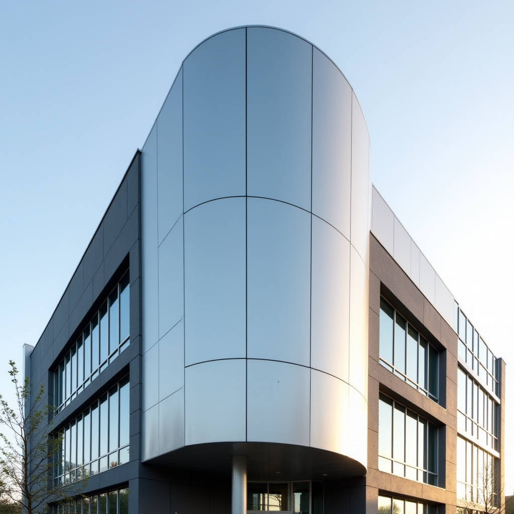
Aluminum Panel Welding sits at the intersection of metallurgical precision and architectural ambition. When a facade design calls for seamless corners, invisible joints, or complex geometric transitions that mechanical fasteners simply cannot deliver, welding becomes the only viable path forward. Yet the process is unforgiving. Solid aluminum cladding panels—typically 2.0mm, 2.5mm, or 3.0mm thick sheets of 1100, 3003, or 5052 alloy—behave very differently under an arc than structural steel. The high thermal conductivity that makes aluminum excellent at dissipating heat also means it pulls heat away from the weld pool at remarkable speed. The oxide layer that protects aluminum from corrosion melts at roughly 2,060°C, while the base metal beneath liquefies at around 660°C. This gap creates a fundamental challenge: you must break through the oxide without burning through the panel. For contractors and facade engineers evaluating whether to weld on site or specify shop-welded assemblies, understanding these dynamics is not optional. It determines whether a building envelope performs for 30 years or develops cracks, leaks, and coating failures in three.
Why Weld Aluminum Facade Panels at All
The default method for installing solid aluminum cladding panels involves mechanical fasteners, aluminum extrusions, and gaskets. This approach works for most rectangular facades. But certain architectural conditions leave no practical alternative to welding. When a design demands floating planes with no visible fixings, or when panels wrap around curved parapets and column covers, mechanical joints introduce visual interruptions that undermine the architectural intent. Welding creates a monolithic surface where individual panels disappear into a continuous skin. Water penetration resistance also improves dramatically. A properly executed continuous weld bead eliminates the capillary gaps that can form between mechanically joined panels, removing a potential path for driven rain. There is also a structural dimension. In high-wind zones—coastal towers, hurricane-prone regions—welded panel assemblies distribute wind loads across a larger area than isolated fastener points, reducing the risk of localized fatigue around screw holes over decades of cyclic loading.
The Metallurgy That Makes Aluminum Welding Difficult
Aluminum does not change color as it approaches its melting point. Steel glows red, then orange, then yellow—giving the welder a visual countdown. Aluminum gives no such warning. It sits there looking solid, then suddenly collapses into a liquid pool. This alone accounts for a significant percentage of burn-through failures on thin-gauge cladding panels. The oxide layer problem compounds the difficulty. Aluminum oxide is ceramic-hard, electrically insulating, and stubbornly stable. If it is not removed immediately before welding—either mechanically with a dedicated stainless steel brush or chemically with acetone—it contaminates the weld pool and creates porosity. The oxide also reforms within seconds of cleaning, so the window between preparation and striking an arc is brutally short. Hydrogen solubility is another hidden trap. Molten aluminum absorbs hydrogen from moisture, hydrocarbons, and atmospheric humidity far more readily than solid aluminum. As the weld solidifies, that hydrogen comes out of solution and forms gas pockets. The result is subsurface porosity that may not be visible on the surface but significantly reduces the effective cross-sectional area of the joint. For a 2.5mm panel, even a 0.3mm line of porosity along the weld root can cut fatigue life by half.
Alloy Selection for Weldable Cladding Panels
Not all aluminum alloys weld equally. The 1xxx series—commercially pure aluminum, typically 1100 or 1050—offers the best weldability of any aluminum family. These alloys are soft, ductile, and free of the alloying elements that cause hot cracking. The trade-off is lower strength: 1100-H14 delivers roughly 110-130 MPa tensile strength, which is adequate for non-structural cladding but marginal for panels that must span large distances without intermediate support. The 3xxx series, particularly 3003 and 3004, adds manganese for moderate strengthening while retaining excellent weldability. 3003-H14 provides approximately 150-170 MPa tensile strength and is the workhorse alloy for welded architectural cladding. The 5xxx series, especially 5052, brings magnesium into the mix and pushes tensile strength to 210-260 MPa. 5052 welds well with proper filler metal selection, but the higher magnesium content requires careful shielding gas coverage to avoid oxide formation during welding. The 6xxx series—6061, 6063—is common in extruded aluminum framing but problematic for welding thin cladding panels. These heat-treatable alloys are prone to hot cracking and lose significant strength in the heat-affected zone. Unless post-weld heat treatment is feasible, 6xxx alloys are generally avoided for welded panel assemblies.
| Alloy Series | Common Grades | Weldability | Typical Tensile Strength (MPa) | Hot Cracking Risk | Best Application |
|---|---|---|---|---|---|
| 1xxx | 1100, 1050 | Excellent | 110-130 | Very Low | Interior cladding, soffits |
| 3xxx | 3003, 3004 | Excellent | 150-170 | Low | General exterior cladding |
| 5xxx | 5052, 5083 | Very Good | 210-260 | Low-Moderate | High-wind facades, marine |
| 6xxx | 6061, 6063 | Fair-Poor | 240-310 | High | Not recommended for panels |
Welding Processes for Thin-Gauge Aluminum Panels
GTAW (TIG Welding)
Gas Tungsten Arc Welding remains the dominant process for architectural aluminum panel welding, and for good reason. TIG gives the welder precise control over heat input, which is critical when working with 2.0mm to 3.0mm material. The foot pedal or thumb control allows real-time amperage adjustment as the weld progresses. AC (alternating current) mode is mandatory for aluminum—the positive half-cycle provides the oxide-cleaning action, while the negative half-cycle delivers penetration. Balance control lets the welder tune this ratio. A setting of 65-75% EN (electrode negative) typically provides the best compromise between cleaning and penetration on 5052 panels. Pure argon shielding gas at 15-20 CFH flow rate is standard. The filler rod must match the base alloy: 4043 for 6xxx-to-3xxx joints, 5356 for 5xxx base metals. Using 4043 on 5052 panels creates a brittle intermetallic zone that will crack under thermal cycling. TIG is slow—a skilled welder might produce 3-5 linear meters of quality weld per hour on 2.5mm panel—but the results are unmatched for cosmetic welds that will be visible on the finished facade.
GMAW (MIG Welding)
For longer production runs, Gas Metal Arc Welding offers higher deposition rates. Spray transfer mode, achieved above roughly 24 volts and 180 amps with 1.0mm or 1.2mm wire, produces a stable arc with minimal spatter. Pulse MIG is increasingly preferred for aluminum panel welding because it reduces heat input while maintaining good fusion. The pulsed current alternates between a high peak for droplet transfer and a low background to maintain the arc, reducing the average heat going into the panel. This matters enormously for thin material: less heat means less distortion, less burn-through risk, and a narrower heat-affected zone. The trade-off is equipment cost. A quality pulse MIG power source with a push-pull wire feed system designed for aluminum represents a significant investment—but for a facade fabrication shop producing hundreds of welded panel assemblies per month, the productivity gains justify the expense. Shielding gas for aluminum MIG is typically pure argon; argon-helium blends can improve wetting on thicker sections but are rarely necessary for cladding-gauge material.
Extrusion Welding
Extrusion welding of aluminum panels, as reviewed in recent academic literature, represents a specialized solid-state process distinct from fusion welding. In this method, a rotating tool generates frictional heat and plastic deformation, forcing material through a die to create a continuous joint. The process operates below the melting point, which eliminates solidification cracking and significantly reduces porosity. The microstructure in the weld zone shows fine, equiaxed grains that often exceed the base metal in hardness. For architectural cladding, extrusion welding is primarily relevant for joining aluminum panel edges in a factory setting, particularly for long linear seams where consistent quality over many meters is required. The process is not portable and cannot be used for site welding, but it offers an interesting alternative for prefabricated welded panel assemblies where the joint will be ground flush and coated.
Distortion Control: The Hidden Cost Driver
Aluminum expands at roughly twice the rate of steel when heated—approximately 23 × 10⁻⁶ per °C versus 12 × 10⁻⁶. This thermal expansion coefficient, combined with high thermal conductivity, means that heat introduced during welding spreads rapidly and causes significant dimensional changes. A 2.0mm aluminum panel welded along a 1-meter seam can easily bow 3-5mm out of plane if distortion is not managed. For a facade where panels must align within 2mm tolerance across a 10-meter grid, this is unacceptable. Several strategies reduce distortion. Backing bars made of copper or aluminum act as heat sinks, pulling heat away from the weld zone and constraining the panel. Intermittent welding—stitch welding with 50-75mm beads separated by equal gaps—reduces total heat input. Back-step welding, where each short bead is laid in the opposite direction of the overall weld progression, distributes thermal stress more evenly. For critical cosmetic panels, pre-setting the panel with a slight reverse bend before welding can compensate for the expected distortion. None of these techniques eliminate distortion entirely; they manage it to within acceptable limits. The most effective approach is to minimize the total length of weld on each panel through smart design—a principle that good facade engineers apply from the earliest concept stage.
Post-Weld Coating Challenges
Most solid aluminum cladding panels carry a factory-applied PVDF (polyvinylidene fluoride) coating, typically 25-35 microns thick per AAMA 2605 specifications. This coating is applied to flat sheet before forming and certainly before welding. The heat of welding destroys the coating in the immediate vicinity of the weld—typically a band 10-20mm wide on each side of the joint. This creates a corrosion vulnerability and an aesthetic problem. The standard solution is to specify shop-welded panels that are welded before coating. The entire welded assembly is then sent through the pretreatment and coating line as a single unit. This approach delivers a uniform finish across welds and base metal, with no visible transition. The limitation is size: the coating line and curing oven impose maximum dimensions, typically around 4 meters by 1.5 meters for a standard vertical line. Larger welded assemblies may require a horizontal coating line or manual spray application, which introduces variability in film thickness and appearance. For site-welded joints, the situation is more difficult. The weld area must be ground flush, cleaned, and coated with a field-applied touch-up system. These two-component polyurethane or fluoropolymer touch-up paints can achieve reasonable color match and corrosion protection, but they will never match the factory PVDF coating in terms of gloss consistency, chalk resistance, or long-term color stability. AAMA 2605 requires 10-year South Florida exposure with maximum 5 Delta E color change; field-applied touch-ups typically achieve 3-5 years before visible fading becomes apparent.
Quality Verification and Testing Protocols
For welded aluminum panel assemblies destined for architectural facades, visual inspection is necessary but insufficient. Dye penetrant testing (PT) provides a simple, low-cost method for detecting surface-breaking defects. A red dye is applied to the cleaned weld, allowed to dwell for 10-15 minutes, then the excess is removed and a developer is applied. Any crack or surface porosity bleeds red against the white developer background. This test can be performed in the fabrication shop or on site with minimal equipment. For critical structural welds—brackets, support frames, attachment points—radiographic testing (RT) or ultrasonic testing (UT) may be specified. RT provides a permanent film record showing internal porosity, lack of fusion, and tungsten inclusions. UT requires a skilled operator but can detect subsurface defects without the safety exclusion zones required for radiography. Destructive testing on sample coupons provides the most definitive quality data. A tensile test across the weld should achieve at least 80% of the base metal tensile strength for a properly executed weld on 3003 or 5052 alloy. A bend test—bending a welded coupon 180 degrees around a mandrel—reveals ductility and fusion quality. Cracking or opening at the weld face indicates incomplete fusion or excessive porosity. For a typical facade project, one destructive test per 100 linear meters of production weld is a reasonable quality assurance frequency.
Site Welding vs. Shop Welding: A Practical Decision Framework
Every project team eventually faces the question: weld in the factory or weld on site? The answer depends on panel size, coating requirements, access conditions, and local labor capability. Shop welding offers controlled conditions—clean, dry, wind-free environment; consistent power supply; dedicated fixturing; and immediate access to material handling equipment. The weld quality is inherently higher and more consistent. Panels can be welded before coating, eliminating the touch-up problem. The downside is transport: large welded assemblies are more expensive to ship and more vulnerable to handling damage. Site welding solves the transport problem but introduces weather dependence, access difficulties, and the touch-up coating challenge. Wind speeds above 8 km/h can disrupt shielding gas coverage on TIG welds, leading to porosity. Ambient temperatures below 10°C require preheating to drive off condensation and reduce the thermal shock to the weld zone. For most projects, the optimal strategy is to maximize shop welding and minimize site welding. Design panel joints so that the only site connections are mechanical, with all welding completed in the factory. When site welding is unavoidable—curved feature walls, complex parapet terminations—plan the work for favorable weather windows and budget for the additional quality control and touch-up coating that will be required. Suppliers like Futeng® can provide shop-welded panel assemblies to project specifications, with the welding completed under factory conditions and the entire assembly coated as a single unit before shipping.
Filler Metal Selection and Its Consequences
The choice of filler alloy is not a minor detail—it determines the corrosion resistance, strength, and color match of the finished weld. For welding 3003 panels, 1100 filler provides a good color match after anodizing but lower strength. ER4043 (Al-Si) filler offers excellent fluidity and crack resistance, making it forgiving for less experienced welders, but it contains silicon that turns dark gray when anodized. If the weld will be visible and anodized, this color mismatch is unacceptable. ER5356 (Al-Mg) filler provides higher strength and better color match for 5052 base metal, but it is more prone to hot cracking if the welding technique is not precise. For PVDF-coated panels where the weld will be hidden by the coating, the anodizing color issue is irrelevant—ER4043 becomes the practical choice for its weldability advantages. One often-overlooked factor: filler metal must be stored correctly. Aluminum filler rods and wires absorb moisture from the atmosphere. Rods stored in a humid shop for weeks can introduce hydrogen into the weld pool, causing porosity that no amount of technique can prevent. Dedicated rod storage at 30-40% relative humidity, or baking rods at 120°C for two hours before use, eliminates this variable.
Thermal Management in Thin Panels
The thinner the panel, the more critical heat management becomes. On 2.0mm material, the difference between full penetration and a burn-through hole can be less than 10 amps of welding current. Experienced aluminum panel welders develop a feel for the heat saturation point—the moment when the panel has absorbed enough heat that the weld pool suddenly becomes more fluid and harder to control. At this point, the only correct response is to stop and let the panel cool. Pushing through leads to excessive melt-through, wide heat-affected zones, and distortion. For long continuous welds on thin panels, a pulsed technique—weld 50-75mm, pause 10-15 seconds, resume—keeps the average panel temperature below the danger threshold. Some fabricators use compressed air cooling directed at the weld zone from the back side of the panel, though this must be done carefully to avoid introducing moisture or contaminants. Water-cooled backing bars are effective for production welding but require careful setup to ensure consistent contact along the entire weld length. The Miller welding resource library provides detailed parameter tables for various aluminum thicknesses and joint configurations.
Structural Implications for Facade Engineering
A welded aluminum panel assembly behaves differently under wind load than a mechanically fastened one. The continuous weld seam distributes stress along its entire length rather than concentrating it at discrete fastener points. For a panel subjected to a 2.0 kPa wind load (typical for mid-rise buildings in moderate wind zones), the stress at a mechanical fastener point can reach 40-60 MPa, while the same load distributed along a continuous weld might produce only 15-25 MPa in the joint. This has implications for fatigue life. Aluminum has no fatigue limit—unlike steel, which can endure infinite cycles below a certain stress threshold, aluminum will eventually fail under any cyclic loading. The lower the stress amplitude, the longer the fatigue life. Welded joints that reduce peak stress therefore extend the service life of the facade. The Aluminum Association publishes fatigue design data for welded aluminum structures that facade engineers should reference when designing welded panel assemblies for high-cycle applications. The heat-affected zone adjacent to the weld typically has lower strength than the base metal—for 5052-H32, the HAZ strength may drop to the annealed condition, roughly 170 MPa versus 210 MPa for the unaffected base metal. This strength reduction must be accounted for in the structural analysis, particularly for panels spanning between supports where the weld runs parallel to the span direction.
Practical Recommendations for Specifying Welded Aluminum Panels
Specifying welded aluminum panel assemblies requires more detail than simply noting "panels to be welded" on a drawing. The specification should address alloy grade, filler metal, welding process, acceptance criteria, and coating sequence. For general exterior cladding on commercial buildings, 3003-H14 panels with ER4043 filler, TIG-welded in the shop, ground flush, and PVDF-coated as a complete assembly represents a proven, cost-effective specification. For coastal or high-wind applications, upgrading to 5052-H32 with ER5356 filler provides additional strength and corrosion resistance. The specification should reference relevant standards: AWS D1.2 for structural welding of aluminum, AAMA 2605 for PVDF coating performance, and ASTM B209 for aluminum sheet specifications. Weld acceptance criteria should be clearly stated—typically Class B per AWS D1.2 for architectural welds, which permits minor undercut and porosity within defined limits. Requiring Class A (aircraft-quality) welds for architectural panels adds cost without commensurate benefit. The most successful projects involve the fabricator early in the design process. A fabricator with aluminum panel welding experience can identify potential problems—joints that will be difficult to weld, distortion-prone geometries, coating access issues—before they become expensive change orders. This early collaboration between architect, facade engineer, and fabricator consistently produces better outcomes than a design-bid-build approach where the fabricator first sees the drawings at tender stage.
The decision to weld aluminum cladding panels should never be casual. It commits the project to a specific set of metallurgical realities, quality control requirements, and long-term maintenance considerations. But when the architectural vision demands what only welding can deliver—true visual continuity, superior water penetration resistance, and distributed load paths—the investment in proper aluminum panel welding pays back over decades of facade performance. The key is understanding the constraints: choose the right alloy, match the filler metal to the application, control heat input relentlessly, verify quality through testing, and plan the coating strategy from the start. These principles, applied consistently, separate facades that endure from those that fail prematurely.