CNC Machining Aluminum Panel Perforation Engineering for Precision Facade Cladding
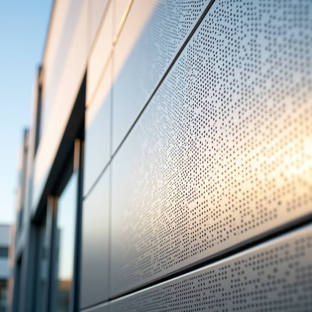
Every architect who has pushed for a perforated facade design knows the moment: the shop drawings come back, and the hole pattern that looked immaculate on screen has drifted into a mess of misaligned perforations, ragged edges, and panel warping. The root cause is almost never the design itself. It is the gap between what a CAD file demands and what a machine actually delivers. Closing that gap requires moving beyond generic CNC routing and into a disciplined understanding of how CNC machining aluminum panel processes interact with sheet metal behavior, tooling wear, and real-world tolerances. This article examines the specific engineering challenges that determine whether a CNC-machined aluminum panel emerges from the machine flat, accurate, and ready for installation—or becomes another costly rework.
Why Perforated Aluminum Panels Demand a Different CNC Mindset
Standard CNC routing on aluminum sheet is straightforward when the goal is cutting a perimeter shape or milling a few mounting slots. Perforated panels change the equation entirely. A single 1.2-meter by 2.4-meter panel might contain 3,000 to 8,000 individual perforations. Each hole represents a tool entry and exit. Each entry imposes a thermal spike at the cutting edge. Multiply that by thousands, and the cumulative heat load becomes the dominant variable controlling dimensional accuracy.
The problem is not theoretical. Aluminum alloys commonly used in architectural cladding—particularly 5052, 5083, and 6061-T6—have coefficients of thermal expansion hovering around 23.6 × 10⁻⁶ /°C. On a 2.4-meter panel, a temperature rise of just 15°C during machining translates to roughly 0.85 mm of linear expansion. That is enough to push hole positioning outside the ±0.5 mm tolerance that most facade specifications demand. When the panel cools, it contracts. The holes that were machined at elevated temperature are now in slightly different positions than the CAD file intended. This is not a programming error. It is physics, and it requires a machining strategy that manages heat rather than simply ignoring it.
Beyond thermal effects, perforation density introduces a structural problem. Remove 30% to 50% of the material from a solid aluminum sheet, and the remaining web structure becomes significantly less rigid. A panel that was perfectly flat before machining can bow, twist, or develop oil-canning during the perforation process because internal stresses in the sheet are released unevenly. Shops that treat perforated CNC machining aluminum panel work as a simple toolpath problem inevitably produce panels that fail flatness inspection on site.
Tooling Strategy: The Difference Between Clean Holes and Burr-Ridden Rejects
Tool selection for CNC machining aluminum panel perforations is not a matter of grabbing whatever end mill is in the tool changer. The geometry of the cutting tool directly determines edge quality, burr formation, and tool life across thousands of penetrations.
For circular perforations ranging from 3 mm to 25 mm in diameter—the most common range in architectural perforated panels—three tool types dominate the conversation:
- Brad point drills with carbide tips provide clean entry and exit on sheet thicknesses up to 3.0 mm. The center spur locates the hole precisely before the cutting lips engage, reducing the risk of walking on the surface. However, brad points wear quickly on aluminum above 2.5 mm thickness due to the abrasive nature of the oxide layer.
- Carbide end mills used in helical interpolation offer the best hole quality for diameters above 10 mm. The tool spirals into the material rather than plunging straight down, which reduces thrust force and minimizes exit burr formation. The trade-off is cycle time: helical interpolation is slower than direct drilling.
- Specialty perforation tooling with diamond-like carbon (DLC) coatings has emerged as a viable option for high-volume architectural work. These tools resist aluminum adhesion to the cutting edge—a phenomenon known as built-up edge (BUE)—which is the primary cause of burr formation in long production runs.
The economics of tooling deserve attention. A single carbide drill might cost $12 to $35 and produce 3,000 to 5,000 clean holes in 5052 aluminum before edge quality degrades. On a project requiring 50,000 perforations across 20 panels, that translates to roughly 10 to 17 tool changes. Factoring in machine downtime, tool cost, and operator labor, the per-panel tooling burden can range from $8 to $25 depending on pattern density and material grade. Shops that do not account for this in their quoting process end up losing money on perforated work.
Feed Rate, Spindle Speed, and the Heat Equation
The relationship between spindle speed and feed rate is where CNC machining aluminum panel quality is won or lost. Run the spindle too fast, and friction heating softens the aluminum at the cutting interface, causing material to smear rather than shear cleanly. Run feed rates too slow, and the tool rubs instead of cutting, generating heat without removing material efficiently.
For 5052-H32 aluminum sheet at 2.5 mm thickness—a common architectural specification—the following parameters serve as a starting point for perforation work with a 6 mm carbide drill:
| Parameter | Recommended Range | Notes |
|---|---|---|
| Spindle Speed | 8,000 – 12,000 RPM | Higher speeds risk BUE; lower speeds reduce productivity |
| Feed Rate | 800 – 1,200 mm/min | Adjust based on hole diameter; larger holes tolerate faster feeds |
| Peck Depth | 1.0 – 1.5 mm per peck | Peck drilling breaks chips and reduces heat buildup |
| Coolant | Mist or flood (synthetic) | Dry machining aluminum perforations is not recommended |
| Chip Load | 0.05 – 0.10 mm/tooth | Lower end for small holes; higher for diameters above 12 mm |
These numbers are not gospel. Every machine has its own rigidity characteristics, and every aluminum batch has slightly different temper properties. The point is that parameters must be dialed in per-project, not copied from a generic machining handbook. Shops that invest in test coupons before running production panels catch heat-related issues before they ruin a full sheet of aluminum.
Coolant strategy matters more than many operators realize. Mist coolant systems provide adequate lubrication for most perforation work while keeping the work area visible—important when an operator needs to monitor hole quality in real time. Flood coolant offers superior heat extraction but creates a mess that complicates panel handling. The compromise many architectural fabricators settle on is a high-quality synthetic mist coolant applied through the spindle, which delivers lubrication directly to the cutting edge without obscuring visibility.
Material Selection: Not All Aluminum Sheets Machine the Same
Architects specify aluminum cladding panels primarily on the basis of finish quality, corrosion resistance, and structural performance. Machinists care about a different set of properties: chip formation behavior, hardness, and the material's tendency to gall or build up on cutting edges.
Three alloys dominate architectural CNC machining aluminum panel work:
- 5052-H32 is the workhorse of perforated cladding. Its moderate hardness (60-70 Brinell) and excellent formability make it forgiving during machining. Chips break cleanly, burr formation is manageable with proper tooling, and the alloy's marine-grade corrosion resistance holds up in coastal environments. The downside is that 5052 is not heat-treatable, so any annealing from machining heat cannot be reversed.
- 5083-H116/H321 offers higher strength than 5052 while maintaining good machinability. It is often specified for large-format panels where wind load demands additional stiffness. The higher magnesium content (4.0-4.9%) makes it slightly more prone to BUE, so tool coatings and coolant become more critical.
- 6061-T6 appears less frequently in cladding but is sometimes specified for structural brackets or stiffener components integrated into panel assemblies. Its higher hardness (95 Brinell) and heat-treatable nature make it more challenging to machine cleanly. Chip control is excellent, but tool wear accelerates noticeably compared to 5000-series alloys.
For panels that will receive PVDF fluoropolymer coating after machining, the alloy selection must also account for how the machined edge accepts pretreatment. 5000-series alloys with higher magnesium content can develop a dark oxide smut on machined edges during chemical pretreatment. This smut must be removed before coating, adding a process step that some fabricators overlook until it shows up as adhesion failure in the field.
Flatness Preservation During High-Density Perforation
The single most common rejection reason for perforated CNC machining aluminum panel work is not hole size error or burr problems. It is flatness deviation. A panel that exceeds the allowable flatness tolerance—typically 0.5% of the diagonal dimension per AAMA 609.1—will telegraph every imperfection across the facade once installed.
Flatness problems in perforated panels stem from two sources: residual stress release and machining-induced thermal distortion. Residual stresses are locked into the aluminum sheet during the rolling process at the mill. When material is removed during perforation, these stresses redistribute, and the panel warps to find a new equilibrium. The effect is most pronounced in panels with asymmetric perforation patterns or edge margins that are significantly different from the field pattern.
Several strategies mitigate this:
- Stress-relieved sheet from the mill costs more but dramatically reduces post-machining distortion. Specifying ASTM B209-compliant sheet with a controlled temper (H32 or H321 rather than H34 or H36) provides a more stable starting point.
- Vacuum workholding during machining keeps the sheet flat against the machine bed, but it does not eliminate the spring-back that occurs when vacuum is released. It is a management tool, not a solution.
- Staggered machining sequences that distribute material removal evenly across the panel surface reduce the concentration of stress release in any one area. This requires thoughtful CAM programming rather than simply running a toolpath from one corner to the other.
- Post-machining flattening using a roller leveler or press can recover panels that have moved during machining, but this adds cost and risks distorting hole geometry. It is a corrective step, not a primary strategy.
Fabricators with deep experience in architectural perforation—including Futeng® and similar specialty suppliers—have developed proprietary workholding and sequencing methods that keep flatness within tolerance even on panels with 40% open area. The key is treating flatness as a process variable to be controlled, not a quality check to be performed after the fact.
PVDF Coating Compatibility with CNC-Machined Edges
A perforated panel destined for exterior cladding almost always receives a PVDF (polyvinylidene fluoride) coating after machining. The coating system—typically a 3-coat or 4-coat application with a total dry film thickness of 35-45 microns per AAMA 2605—must adhere uniformly to the face of the panel, the interior of every perforation, and the panel edges.
The machined interior of a perforation presents a coating challenge. The cutting process leaves a surface that is microscopically rougher than the mill finish on the panel face. This roughness can improve mechanical adhesion, but it also creates pockets where pretreatment chemicals can become trapped. If the pretreatment—typically a chrome-based or chrome-free conversion coating—is not thoroughly rinsed from the perforations, residual chemistry attacks the coating from beneath, causing delamination that starts at the hole edges and propagates outward.
Specifying a minimum hole diameter of 6 mm for PVDF-coated perforated panels is not arbitrary. Below this diameter, the combination of coating surface tension and the geometry of the hole makes it difficult to achieve uniform coverage inside the perforation. Some coating applicators push this limit to 4 mm with specialized spray techniques, but the risk of incomplete coverage increases sharply. For panels with sub-6 mm perforations, anodizing may be a more appropriate finish, though it limits color options compared to PVDF.
The coating sequence also matters. Panels should be cleaned, pretreated, and coated after all machining is complete. Machining a coated panel—even with protective film in place—risks chipping at hole edges and creating pathways for moisture ingress behind the coating. The protective film itself can lift during machining, allowing chips to scratch the coated surface beneath.
Cost Drivers in Architectural Perforation Work
Understanding what drives cost in CNC machining aluminum panel perforation helps procurement managers evaluate quotes intelligently and helps fabricators price work profitably. The variables are more nuanced than simply "more holes equals more cost."
| Cost Driver | Low Impact | Medium Impact | High Impact |
|---|---|---|---|
| Hole Count per Panel | < 500 holes | 500 – 2,000 holes | > 2,000 holes |
| Hole Diameter | > 12 mm | 6 – 12 mm | < 6 mm |
| Pattern Complexity | Regular grid | Staggered pattern | Gradient or image-based |
| Open Area Percentage | < 20% | 20% – 40% | > 40% |
| Material Grade | 5052-H32 | 5083-H116 | 6061-T6 |
| Flatness Requirement | Standard (±0.5% diagonal) | Enhanced (±0.3% diagonal) | Critical (±0.2% diagonal) |
Pattern complexity deserves special attention. A regular grid of equally spaced holes is straightforward to program and machine. A gradient pattern where hole density varies across the panel surface—common in architectural feature walls—requires significantly more CAM programming time and often demands variable feed rates to manage the changing thermal load as the tool moves from dense to sparse regions. Image-based perforation patterns, where hole sizes vary to create a visual image when viewed from a distance, represent the highest tier of complexity. Each hole may have a unique diameter, requiring tool changes or complex interpolation paths that extend cycle time dramatically.
For budgeting purposes, a perforated 5052-H32 panel with a regular grid pattern and 25% open area typically adds $45 to $85 per square meter to the base panel cost, depending on hole size and quantity. Gradient patterns can push that to $90 to $150 per square meter. Image-based patterns routinely exceed $200 per square meter in machining cost alone. These figures assume a competent CNC machining aluminum panel setup with appropriate tooling and coolant. Shops attempting this work on underpowered routers or without proper chip management will see higher costs from tool breakage and rework.
Programming Considerations: From CAD to Clean Panel
The CAM programming stage is where many perforation projects succeed or fail. A CAD file showing a beautiful hole pattern does not automatically translate into a machinable panel. The programmer must make decisions about toolpath strategy, entry method, and sequencing that directly affect cycle time, hole quality, and panel flatness.
Several programming practices separate professional architectural perforation work from generic CNC routing:
- Peck drilling cycles (G83) should be used for holes deeper than 1.5× diameter. In 2.5 mm sheet, this means holes below approximately 4 mm diameter benefit from pecking. The peck breaks the chip, clears it from the hole, and allows coolant to reach the cutting edge. Without pecking, chips pack into the hole and generate friction heat that accelerates tool wear.
- Toolpath sequencing should distribute heat across the panel. Machining all holes in one quadrant before moving to the next concentrates heat and creates differential thermal expansion. A better approach is to machine in a pattern that jumps around the panel—similar to the torque sequence on a cylinder head—allowing each area to cool before the tool returns.
- Entry and exit strategy matters for hole quality. A direct plunge generates high thrust force and can deflect the tool, especially on small-diameter holes. A helical or ramped entry reduces this force and produces a cleaner hole start. On exit, reducing feed rate by 30-50% for the last 0.5 mm of material thickness minimizes the burr that forms as the tool breaks through the bottom surface.
- Dwell time at the bottom of each hole should be zero or near-zero. Dwelling generates friction heat without removing material, and on aluminum, this quickly leads to BUE formation.
For projects requiring compliance with AAMA standards for aluminum cladding, the machining documentation should include records of tool changes, spindle speed verification, and in-process inspection data. This level of documentation is increasingly required on large commercial projects where the facade contractor must demonstrate quality control throughout the supply chain.
Quality Verification: Measuring What Matters
Inspection of perforated CNC machining aluminum panel output goes beyond checking a few hole diameters with calipers. A systematic approach catches problems before panels reach the coating line or, worse, the job site.
Key inspection points include:
- Hole position accuracy should be verified on a coordinate measuring machine (CMM) or with a vision-based measurement system, not with a tape measure. The first article from each setup should be fully inspected. Subsequent panels can be sampled, but the first article sets the baseline.
- Burr height on the exit side of holes should not exceed 0.1 mm for panels receiving PVDF coating. Burrs above this height will not be adequately covered by the coating and create corrosion initiation points. A simple burr gauge provides quick go/no-go assessment on the shop floor.
- Flatness should be measured with the panel supported in its intended installation orientation, not lying flat on a surface table. Gravity affects flatness readings on large panels, and a panel that measures flat on a table may show unacceptable deviation when hung vertically.
- Edge condition inside perforations should be examined under 10× magnification on the first article. Any signs of tearing, smearing, or built-up edge indicate that tooling or parameters need adjustment before production continues.
For projects referencing ASTM B209 for aluminum sheet and AAMA 2605 for coating performance, the inspection criteria should be agreed upon between the fabricator and the facade contractor before production begins. There is no universal standard for perforation quality in architectural aluminum; the acceptance criteria are project-specific and should be documented in the quality plan.
Integrating CNC-Machined Panels into the Facade System
A perforated panel does not exist in isolation. It must integrate with the facade's structural framing, accommodate thermal movement, and meet the project's performance requirements for wind load, water penetration, and air infiltration.
The machining process affects this integration in several ways. Perforations reduce the panel's effective section modulus, which means the panel's spanning capability between attachment points is lower than a solid panel of the same thickness. A 2.5 mm solid 5052-H32 panel might span 600 mm between stiffeners. The same panel with 35% open area may require stiffener spacing reduced to 400 mm or less, depending on the perforation pattern and wind load. This structural interaction should be evaluated during the design phase, not discovered during shop drawing review.
Attachment methods also require consideration. Welded studs for clip attachment must be positioned in solid areas of the panel, not on the thin web between perforations. The heat from stud welding can distort the panel locally, and if the stud is too close to a perforation, the weld zone may extend into the hole edge, creating a stress concentration point. A minimum distance of 2× the stud diameter from any perforation edge is a reasonable rule of thumb, though the specific requirement depends on the stud size and welding parameters.
For projects where perforated panels serve as rainscreen elements with an open joint system, the perforations contribute to the panel's effective open area for ventilation and pressure equalization. This must be accounted for in the rainscreen design calculations per ISO 15686 and local building codes. A panel with 25% perforation open area plus 10 mm open joints behaves differently from a solid panel with the same joint width, and the cavity ventilation rate will be higher.
Practical Takeaways for Specifying Perforated CNC-Machined Aluminum Panels
Specifying perforated aluminum cladding is not simply a matter of drawing a pattern and sending it to a fabricator. The specification must address the machining process, the material condition, the coating compatibility, and the quality verification methods. Architects and facade engineers who understand these variables write specifications that produce better outcomes.
The following points summarize the engineering considerations that separate successful perforated panel projects from problematic ones:
- Specify the aluminum alloy and temper explicitly in the contract documents. "Aluminum sheet" is not a specification. 5052-H32 is the appropriate starting point for most architectural perforation work.
- Establish hole position tolerances that are achievable with the specified machining process. ±0.3 mm is achievable on a well-maintained CNC machine with proper tooling. ±0.1 mm is not realistic for production quantities of architectural panels.
- Require first-article inspection with documented measurements of hole position, diameter, burr height, and flatness before production proceeds.
- Address coating compatibility in the specification. The coating applicator must demonstrate that pretreatment and coating processes are validated for the specific perforation geometry.
- Account for the structural implications of perforation in the panel engineering. A perforated panel is not a solid panel with holes; it is a fundamentally different structural element.
The technology to produce stunning perforated aluminum facades exists and is mature. The difference between a project that runs smoothly and one that generates disputes lies in whether the specification and the fabrication process acknowledge the real engineering challenges of CNC machining aluminum panel work. When the architect, the facade engineer, and the fabricator share a common understanding of these challenges, the result is a facade that performs as intended—structurally, aesthetically, and durably.