Aluminum Panel CNC Routing Tooling Parameters and Quality Control for Solid Aluminium Cladding
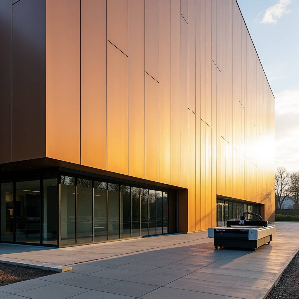
When a cladding panel arrives on site out of square by half a millimeter, the ripple effect across an entire elevation can cost weeks in remedial work. Aluminum Panel CNC Routing is the fabrication stage where that tolerance is either locked in or lost. For solid aluminium cladding panels in the 2.0mm to 3.0mm thickness range, CNC routing determines not just dimensional accuracy but also how cleanly a panel accepts a fold, how consistently a return leg sits against the substructure, and whether the finished facade reads as a single plane or a patchwork of corrections. This article examines the routing parameters, tooling decisions, and quality control protocols that separate a facade that fits first time from one that requires field modification.
Why Routing Accuracy Matters More for Solid Aluminium Than You Think
Solid aluminium panels behave differently on a CNC bed than aluminium composite material. A 2.5mm or 3.0mm sheet of 1100 or 3003 alloy has no polyethylene core to absorb vibration or dampen chatter. Every oscillation in the spindle, every dull edge on the tool, and every deviation in feed rate transfers directly into the cut edge. The result is not just cosmetic. A routed V-groove that varies in depth by 0.1mm along a 3-meter panel will produce a fold line that is visibly inconsistent when light hits the facade at a low angle.
For the project manager overseeing a 20,000-square-meter cladding package, this translates into a simple equation: routing precision equals installation speed. Panels that arrive with consistent fold geometry and clean edge profiles require zero field trimming. Brackets align with pre-routed slots. Return legs sit flush against the substructure without forcing. The installation crew moves across the elevation at the planned rate instead of stopping to troubleshoot every fifth panel.
The tolerance stack in a typical rainscreen assembly starts with the CNC routing. If the panel blank is cut 0.3mm oversize and the V-groove is routed 0.2mm off the intended fold line, the finished panel dimension can drift by a full millimeter. Across a 12-panel horizontal run, that accumulates to 12mm of error that the joint design may not accommodate. The AAMA 508-14 standard for factory-coated aluminium panels references dimensional tolerances that are achievable only when routing parameters are dialed in correctly for the specific alloy and thickness being processed.
Tooling Selection for Solid Aluminium Routing
The tooling decision is where many fabrication shops compromise without realizing the downstream cost. Solid aluminium in the 2.0-3.0mm range demands specific tool geometries that differ from those used for ACM or acrylic.
Carbide Grade and Geometry
Micro-grain carbide tooling with a high cobalt binder content holds an edge longer when cutting 3003-H14 aluminium sheet. Single-flute or two-flute upcut spiral bits in the 6mm to 8mm diameter range provide the chip clearance needed for profile cutting at production speeds. The flute geometry should be polished to prevent aluminium from welding to the tool surface, a problem that escalates rapidly when routing panels with factory-applied PVDF coating. A built-up edge on the tool will tear the coating at the cut line, creating a site for corrosion initiation that may not be visible at installation but will appear within the first 12 months of exposure.
V-Groove Tooling for Fold Lines
For panels that will be folded into trays or cassettes, the V-groove cutter is the single most critical tool in the process. The included angle, typically 90 or 110 degrees depending on the fold angle required, must be ground to a tolerance of ±0.05 degrees. A V-groove that is too shallow leaves excess material in the fold root, causing the panel to spring back after folding. Too deep, and the remaining material thickness at the groove root drops below the 0.3-0.5mm minimum needed to maintain structural integrity at the corner.
The relationship between panel thickness and groove depth is not linear. A 2.5mm panel routed with a 0.4mm remaining land will fold differently than a 3.0mm panel with the same land thickness. The thicker panel has more material to resist the bending moment, so the fold radius will be slightly larger. Shops that process multiple thicknesses need to maintain separate tool offset tables for each, verified with test folds at the start of every production run.
Feeds, Speeds, and the Cost of Getting Them Wrong
Spindle speed and feed rate for solid aluminium routing sit in a narrower window than many operators assume. Run the spindle too fast and the tool generates enough heat to soften the aluminium, leading to edge burrs and coating damage. Run it too slow and the chipload increases to the point where the tool deflects, producing an edge that is not perpendicular to the panel face.
The following table summarizes recommended starting parameters for routing solid aluminium cladding panels with carbide tooling on a rigid industrial CNC router. These values assume proper chip evacuation via either vacuum hold-down with air blast or mist lubrication. Adjustments should be made based on machine rigidity, tool condition, and specific alloy temper.
| Parameter | 2.0mm Panel (1100-H14) | 2.5mm Panel (3003-H14) | 3.0mm Panel (3003-H14) |
|---|---|---|---|
| Spindle Speed (RPM) | 16,000 – 18,000 | 15,000 – 17,000 | 14,000 – 16,000 |
| Feed Rate (mm/min) | 2,500 – 3,500 | 2,000 – 3,000 | 1,800 – 2,500 |
| Chipload (mm/tooth) | 0.08 – 0.12 | 0.07 – 0.10 | 0.06 – 0.09 |
| V-Groove Depth (mm) | 1.60 – 1.70 | 2.05 – 2.15 | 2.50 – 2.60 |
| Remaining Land (mm) | 0.30 – 0.40 | 0.35 – 0.45 | 0.40 – 0.50 |
| Recommended Tool Diameter | 6mm single-flute | 6-8mm single-flute | 8mm two-flute |
| Cooling Method | Air blast minimum | Mist or air blast | Mist recommended |
These figures are starting points, not absolutes. A shop running a heavy gantry router with linear rails and servo drives can push the upper end of these ranges. A lighter machine with rack-and-pinion drive will need to stay at the lower end to maintain edge quality. The operator who understands this distinction and adjusts accordingly produces panels that fit. The one who runs the same program regardless of machine condition generates callbacks.
Vacuum Hold-Down and Material Fixturing
Solid aluminium sheet presents a hold-down challenge that ACM does not. A 2.5mm aluminium panel measuring 1500mm x 3000mm weighs approximately 30 kilograms. When the router tool engages the material, the cutting forces can lift the sheet if vacuum pressure is inadequate or if the spoil board is worn. A panel that shifts by even 0.5mm during a profile cut will produce a trapezoid instead of a rectangle, and that error may not be caught until the panel is offered up on site.
Vacuum systems for aluminium routing should deliver a minimum of 20-25 inches of mercury at the spoil board surface, distributed through a grid of zones that can be activated selectively based on panel size. The spoil board itself needs to be surfaced flat to within 0.1mm across the entire bed, and this surfacing operation should be repeated at intervals determined by production volume, not by a calendar. A shop routing 500 panels per week may need to resurface every Monday morning. One routing 50 panels per week might go a month between resurfacing.
For panels with pre-applied PVDF or FEVE coating, the spoil board surface must be clean and free of aluminium chips that could embed in the coating under vacuum pressure. A sacrificial interlayer of thin MDF or polyethylene sheet between the coated panel face and the spoil board is standard practice in shops that understand the cost of a rejected panel versus the cost of the interlayer material.
Nesting Efficiency and Material Yield
Raw aluminium sheet in the 2.0-3.0mm thickness range represents a significant portion of the total panel cost. Nesting software that optimizes part placement on the sheet can reduce waste from an industry average of 15-20% down to 8-12% on a well-planned project. The difference on a 10,000-square-meter facade can amount to several tons of aluminium that are not purchased, not handled, and not sent to scrap recycling.
Effective nesting for cladding panels requires the software to account for grain direction constraints. Aluminium sheet has a rolling direction, and panels specified with a particular surface finish may need to be oriented consistently relative to that grain. If the nesting algorithm rotates parts to maximize yield without respecting grain direction, the resulting facade will show visible variation in reflectivity across adjacent panels, particularly under the low-angle sunlight conditions common in the morning and late afternoon.
Common-line cutting, where adjacent panel edges share a single tool path, further improves material utilization and reduces cycle time. However, it requires the router to maintain tight tolerances, because any deviation in that shared cut line affects two panels simultaneously. The shops that successfully implement common-line cutting are those that have already mastered the tooling and parameter fundamentals described above.
Coating Integrity During Routing Operations
PVDF-coated solid aluminium panels arrive at the CNC router with a coating system that has already passed quality control at the coating line. The routing operation must preserve that coating integrity, particularly at the cut edges and fold lines where the coating is most vulnerable.
The primary risk is coating delamination at the cut edge. A dull tool tears rather than shears the coating, creating a ragged interface where moisture can penetrate between the coating and the aluminium substrate. This failure mode is referenced in AAMA 2605-22, the voluntary specification for high-performance organic coatings on aluminium extrusions and panels, which sets adhesion requirements that must be maintained through all fabrication steps including routing.
Secondary risks include heat-affected coating discoloration near the cut line, which occurs when spindle speed is too high or feed rate too low, and scratching of the coated surface from chip contact during routing. Both are preventable through parameter optimization and chip management. An air blast directed at the tool-material interface clears chips before they can accumulate and abrade the panel surface. For shops that use mist lubrication, the coolant must be compatible with the PVDF chemistry to avoid staining or softening the coating.
Futeng® has addressed these coating preservation challenges in their solid aluminium panel production by integrating routing parameter validation with their in-house PVDF coating line, ensuring that the routing team receives panels with documented coating properties and can adjust tooling and speeds accordingly before production begins.
Quality Verification After Routing
Dimensional inspection of routed panels should not wait until the panel reaches the folding station. In-process verification at the router, using a calibrated digital caliper or a coordinate measuring arm for complex profiles, catches deviations before they propagate through the remaining fabrication steps.
The inspection checklist for a routed solid aluminium panel includes at minimum: overall length and width at three positions along each edge to check for squareness; V-groove depth at the start, center, and end of each fold line; remaining land thickness measured with a ball micrometer; edge perpendicularity; and coating condition at all cut edges under 10x magnification. Panels with fastener holes or bracket slots should have those features checked for position relative to the panel datum edges, with a tolerance of ±0.2mm for holes that will receive structural fasteners.
Statistical process control applied to these measurements can identify tool wear trends before they produce out-of-tolerance panels. If V-groove depth measurements show a gradual increase over the course of a production run, the tool is wearing and the remaining land is getting thinner. Replacing the tool at a predetermined wear limit, rather than waiting for a failed inspection, keeps the entire batch within specification.
The American Architectural Manufacturers Association (AAMA) provides reference standards for aluminium panel fabrication tolerances. The ISO 2768-1 general tolerances for linear dimensions also apply when project specifications reference international standards. For projects in the European market, EN 485 for aluminium sheet and strip sets the baseline material properties that routing parameters must accommodate.
Machine Rigidity and Long-Term Repeatability
The difference between a router that holds ±0.1mm and one that drifts to ±0.3mm over an 8-hour shift often comes down to machine construction. A welded steel frame with stress-relieved joints maintains geometry better than a bolted aluminum extrusion frame. Linear guides with preloaded bearing blocks resist deflection under cutting loads. Servo motors with absolute encoders eliminate the need for homing cycles and maintain position accuracy through power cycles.
For the procurement manager evaluating a cladding supplier, the router's capability is not an abstract specification. It is a predictor of how many panels will need to be remade, how many site modifications will be required, and ultimately whether the installation stays on schedule. A supplier that has invested in a rigid, well-maintained CNC routing platform with proper tooling and documented quality procedures will deliver panels that fit. The cost of that capability is embedded in the panel price, but it is almost always less than the cost of the delays and rework that result from routing that is just good enough.
The Metal Building Manufacturers Association (MBMA) and The Aluminum Association both publish technical resources relevant to aluminium panel fabrication, including guidance on alloy selection and fabrication practices that inform routing parameter decisions.
Integrating Routing with Downstream Processes
CNC routing does not exist in isolation. The panel that comes off the router moves to folding, then to fastener insertion or bracket attachment, then to packaging. Each of these downstream processes depends on the accuracy of the routing that preceded it.
A panel routed with consistent V-groove geometry will fold to the specified angle with predictable springback. The folding operator can set the press brake once and run the entire batch. A panel with variable groove depth requires constant adjustment at the brake, slowing production and increasing the probability of an over-bent or under-bent panel reaching the installation site.
Similarly, pre-routed holes for rainscreen bracket attachment must align with the bracket mounting pattern. A misalignment of 0.5mm at the router becomes a bracket that does not seat properly, which in turn affects the panel's position in the facade plane. The fix on site typically involves enlarging the hole, which compromises the weather seal and introduces the potential for water ingress at the fastener.
For large-scale projects, the routing program should be validated through a first-article inspection process. Route one complete set of panel types, fold them, assemble them with their brackets, and verify the assembly against the shop drawings. This catches program errors, tool offset issues, and material behavior quirks before they affect the entire production batch. The time invested in first-article validation is recovered many times over in reduced rework and avoided site delays.
Aluminum Panel CNC Routing, when executed with the right tooling, parameters, and quality controls, produces cladding panels that fit the substructure as designed. The alternative is a facade that requires constant adjustment, generates waste, and erodes the margin on a project that may have been priced tightly from the start. For the contractor, the architect, and the building owner, the difference is visible in the finished elevation, where consistent joint widths and flat panel planes signal a fabrication process that was under control from the first cut to the last.