Precision Aluminum Panel V Grooving for Zero Radius Facade Corners and Tight Fold Tolerances
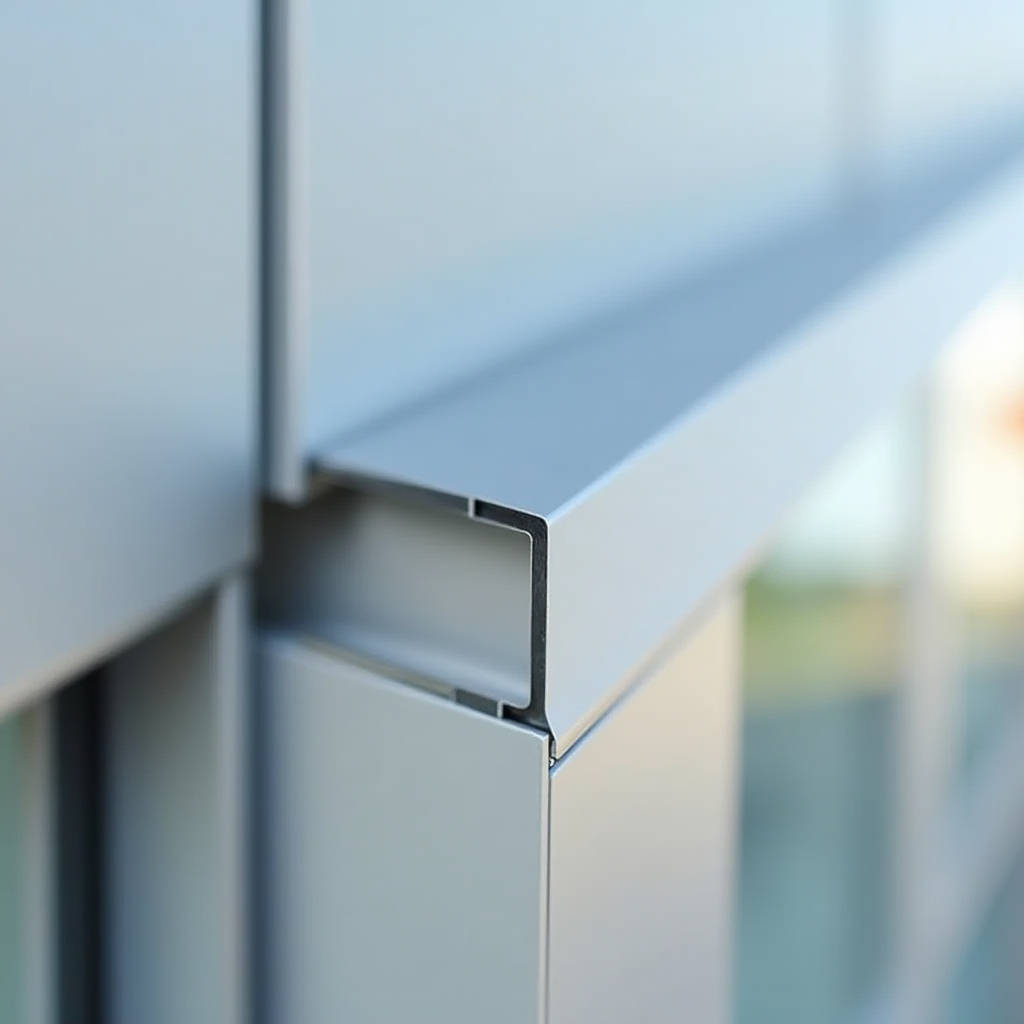
When a facade design calls for razor-sharp corners and tight geometric folds, standard brake press bending falls short. Aluminum Panel V Grooving solves this by removing a precise V-shaped channel from the back side of a solid aluminum sheet, leaving a thin web of material at the face. This web acts as a hinge, allowing the panel to fold cleanly into a sharp 90-degree corner with an external radius of essentially zero. The result is a crisp, monolithic appearance that architects specify for high-end commercial towers, museum exteriors, and corporate headquarters where visual precision is non-negotiable.
Why Solid Aluminum Panels Demand Grooving Over Brake Forming
Solid aluminum sheets in thicknesses of 2.0mm, 2.5mm, and 3.0mm behave differently from composite materials during bending. When a brake press forms a solid 3.0mm 3003-H14 aluminum sheet, the outer radius stretches and the inner radius compresses. This creates a rounded edge profile with a minimum external radius typically equal to the material thickness. For a 3.0mm sheet, you get a 3.0mm radius corner. That might sound small, but under grazing sunlight or uplighting on a facade, rounded corners cast soft shadows that read as fuzzy or imprecise from street level.
Aluminum Panel V Grooving changes the equation entirely. By cutting a V-groove to a depth of approximately 2.7mm on a 3.0mm sheet, the remaining 0.3mm of solid aluminum at the face becomes the bend zone. The panel folds along this pre-weakened line, producing an external corner radius that can be as tight as 0.5mm to 1.0mm. The visual difference is stark: where a brake-formed corner looks like bent metal, a V-grooved corner looks like a solid block of aluminum machined into shape.
This technique matters most on projects where panels join at compound angles, where column wraps require seamless joints, or where facade elements transition from wall to soffit with zero tolerance for visual softness. General contractors who have worked on both types of detailing understand that the grooved approach eliminates the need for corner extrusions or cover trims, reducing part count and simplifying installation sequencing.
The CNC Grooving Process and Depth Control
Modern Aluminum Panel V Grooving relies on CNC-controlled spindles running carbide or diamond-tipped V-bits. The machine bed holds the aluminum sheet flat via vacuum suction or mechanical clamps while the cutting head travels along programmed toolpaths. Depth accuracy is the single most critical variable. Too shallow, and the remaining web is too thick to fold cleanly, causing cracking along the bend line or requiring excessive force that distorts the panel. Too deep, and the cutter scores the visible face, creating a witness line that ruins the panel and sends it to scrap.
For 2.0mm solid aluminum, operators typically target a remaining web thickness of 0.20mm to 0.25mm. For 2.5mm stock, the web sits at 0.25mm to 0.30mm. For 3.0mm panels, the sweet spot is 0.30mm to 0.35mm. These numbers assume 3003-H14 alloy, which offers a good balance of formability and strength. Higher-strength 5052-H32 alloy requires slightly thicker webs to prevent stress cracking during folding, typically adding 0.05mm to each target.
Temperature matters too. Aluminum becomes more brittle at low temperatures. Shops fabricating in unheated facilities during winter months should account for this by adjusting groove depth slightly shallower or warming the material before folding. A panel that folds perfectly at 22°C may crack at 5°C with identical groove parameters.
ASTM B209 governs the dimensional tolerances for aluminum sheet used in architectural applications. When specifying grooved panels, referencing this standard ensures the base material meets flatness and thickness uniformity requirements before grooving begins.
Tooling Selection and Groove Geometry
The V-groove angle dictates the final fold angle. For a 90-degree corner, the groove must be cut at 90 degrees. For a 135-degree fold, the groove angle is 45 degrees. The math is straightforward: the groove angle equals 180 degrees minus the desired fold angle. But practical execution involves more nuance than geometry alone.
Carbide V-bits in diameters from 6mm to 12mm handle most architectural aluminum work. The bit diameter affects the groove width at the surface. A 90-degree bit cutting 2.7mm deep into a 3.0mm sheet produces a groove approximately 5.4mm wide at the back surface. This width must be accounted for in the panel's flat pattern development. If the groove width is not factored into the unfolded dimensions, the finished panel will be undersized by the cumulative groove width across all bends.
Tool wear is a real concern in production runs. A dull bit tears rather than cuts the aluminum, leaving a ragged groove bottom that concentrates stress and promotes cracking during folding. Production managers should track linear meters of grooving per bit and replace tooling on a schedule rather than waiting for visible quality degradation. For 3003 aluminum, carbide bits typically deliver 800 to 1,200 linear meters of clean grooving before replacement is warranted. Diamond-coated bits extend this to 3,000 to 5,000 meters but at roughly three times the tooling cost.
Flat Pattern Development and Dimensional Accuracy
Every V-groove removes material, and that material removal changes the panel's developed length. The bend deduction for a grooved fold differs fundamentally from a brake-formed bend. With brake forming, the bend allowance is calculated based on the neutral axis shift and the bend radius. With Aluminum Panel V Grooving, the deduction is simpler: the panel folds exactly at the root of the groove, and the two legs meet with essentially zero radius.
The practical bend deduction for a 90-degree V-grooved fold on 3.0mm material is approximately 1.5mm to 2.0mm per bend, depending on the exact web thickness and folding method. This means a panel with four grooved bends forming a rectangular box will have a total developed length roughly 6mm to 8mm shorter than the sum of its external dimensions. Getting this wrong means panels that don't fit on site, and on a facade with hundreds of panels, cumulative errors cascade into installation nightmares.
CNC grooving machines with automatic tool height calibration can hold depth tolerances of ±0.03mm across a full sheet. This repeatability is what makes grooved panel systems viable at scale. Manual grooving on a panel saw, while possible for small runs, introduces operator-dependent variability that makes consistent dimensional control difficult across more than a few dozen panels.
Material Behavior During Folding
Once grooved, the panel must be folded. The folding method influences the final corner quality. Hand folding with a purpose-built folding table works for small panels and short runs. For production volumes, pneumatic or hydraulic folding beams apply controlled pressure along the entire bend line simultaneously, reducing the risk of twisting or uneven folding.
The thin web of aluminum remaining at the groove root undergoes plastic deformation during folding. This is by design. The web stretches slightly on the outer fibers and compresses on the inner fibers, exactly as a solid hinge would. The difference is that the web is thin enough that the strain is distributed across a very small zone, so the external face remains flat and undisturbed.
One failure mode to watch for is orange-peel texture on the folded corner. This happens when the grain structure of the aluminum is too coarse, or when the web is too thick relative to the material's ductility. 3003 alloy with H14 temper generally avoids this issue, but 5052-H32 can sometimes show surface roughening at the fold if the web exceeds 0.4mm. Specifying the correct alloy and temper for the application prevents this problem before it reaches the shop floor.
Coating Considerations for Grooved Panels
Most architectural solid aluminum panels receive a PVDF (polyvinylidene fluoride) coating system, typically a 70% PVDF resin-based formulation applied as a two-coat or three-coat system. AAMA 2605 sets the performance standard for high-performance architectural coatings, requiring a minimum total dry film thickness of 30 microns for a two-coat system and 40 microns for a three-coat system.
The coating sequence relative to grooving matters. There are two approaches: coat-then-groove and groove-then-coat. Each has trade-offs. Coating first means the groove cuts through the coating at the bend line, exposing bare aluminum at the fold. This is acceptable for interior applications or sheltered exterior locations, but for exposed facades, the uncoated groove root becomes a potential corrosion initiation point. Grooving first, then coating, ensures the PVDF system wraps into the groove and protects the fold zone. However, coating after grooving requires careful pretreatment to ensure adhesion inside the narrow groove channel.
For projects in coastal or industrial environments, groove-then-coat is the safer specification. The incremental cost is modest, typically adding 5% to 8% to the coating line cost, but the corrosion protection benefit is substantial over a 20-year facade service life. Manufacturers like Futeng® have invested in pretreatment lines specifically designed to handle grooved panels, ensuring chromate conversion coating reaches into the groove geometry before PVDF application.
| Coating Sequence | Corrosion Protection at Groove | Relative Cost | Best Application |
|---|---|---|---|
| Coat-then-Groove | Bare aluminum exposed at fold | Base cost | Interior cladding, sheltered soffits |
| Groove-then-Coat | Full PVDF coverage including groove | +5% to 8% | Exterior facades, coastal zones |
| Groove-then-Anodize | Anodic layer grows into groove | +10% to 15% | Premium architectural, high-traffic areas |
Grooving vs. Routing for Panel Edges
While V-grooving creates fold lines, edge routing serves a different purpose. Routing removes material from the panel perimeter to create rebates, notches, or interlocking profiles. Some facade systems combine both processes: V-grooves for the main folds and routed edges for panel-to-panel joinery. Understanding the distinction helps when communicating with fabricators.
V-grooving uses a pointed tool that cuts a triangular channel. Routing uses an end mill that cuts a rectangular or stepped profile. The two processes often run on the same CNC machine with automatic tool changers, but the tooling, feed rates, and depth strategies differ. Routing typically runs at higher feed rates because the chip load is distributed across a flat-bottom tool, whereas V-grooving concentrates cutting forces at the tool tip.
For panels that require both operations, programming the sequence correctly avoids quality issues. V-grooving should generally be performed before routing, because the grooving operation can distort a panel that has already had its edges routed thin. The remaining material around a routed edge may not have enough stiffness to resist the cutting forces of the V-bit, leading to chatter and poor groove quality.
Quality Inspection Protocols
A proper quality control regimen for Aluminum Panel V Grooving starts at the machine and continues through folding and final inspection. Key checkpoints include groove depth verification using a dial depth gauge or laser profilometer, web thickness measurement at multiple points along each groove, and fold angle verification using a digital protractor.
Groove depth consistency across a panel matters because variations translate directly into fold angle variations. A groove that varies from 2.65mm to 2.75mm depth on a 3.0mm panel will produce a fold angle that varies by approximately 1 to 2 degrees from end to end. On a 3-meter-long panel, this angular error manifests as a gap at the panel joint that can exceed 5mm, far beyond acceptable architectural tolerances.
Visual inspection under raking light reveals surface defects that normal overhead lighting misses. Waviness along the fold line, micro-cracking at the groove root, or coating delamination at the bend are all easier to spot when light strikes the panel at a shallow angle. This inspection step adds minutes per panel but catches defects that would otherwise be discovered only after installation, when remediation costs multiply.
The AAMA 2605 specification provides benchmarks for coating performance that apply equally to grooved and non-grooved panel surfaces. Adhesion testing per ASTM D3359 after folding confirms that the coating system withstands the bending strain without delamination.
Production Throughput and Cost Factors
CNC grooving speed depends on material thickness, groove depth, and tool diameter. For 3.0mm 3003 aluminum with a 90-degree groove at 2.7mm depth, typical feed rates range from 3 to 6 meters per minute. A panel measuring 1.2m x 2.4m with four grooves along the long edges might require 9.6 linear meters of grooving, translating to roughly 2 to 3 minutes of machine time per panel.
Setup time often dominates for small batches. Programming a new panel geometry, loading tooling, and verifying the first article can take 30 to 60 minutes regardless of whether the run is 5 panels or 500. This makes grooving economically favorable for projects exceeding roughly 50 panels, where the setup cost amortizes across sufficient volume. For very small runs, manual grooving on a panel saw may be more cost-effective despite lower precision.
Material yield is another cost consideration. Grooving is a subtractive process that removes aluminum, but the material removed is minimal compared to the panel area. A 2.7mm deep, 5.4mm wide groove across 10 meters of linear grooving removes approximately 73 cubic centimeters of aluminum, weighing about 200 grams. The real material cost driver is not the removed aluminum but the scrap generated from panels that fail inspection due to grooving defects.
Common Defects and Their Root Causes
Cracking at the fold line is the most frequent defect encountered in Aluminum Panel V Grooving. Root causes include excessive web thickness, material temper that is too hard for the fold angle, groove bottom roughness from worn tooling, and folding at low ambient temperatures. The fix depends on diagnosis: measure the web thickness, check the tool condition, verify the alloy and temper, and control the shop environment.
Witness lines on the panel face occur when the V-bit penetrates too deeply and scores the visible surface. Even a 0.05mm scratch on the face is visible under certain lighting conditions and constitutes a reject by architectural standards. Depth calibration using a touch-off sensor before each production run prevents this problem. Some shops also run a test groove on a scrap piece and fold it to verify settings before cutting production panels.
Twisted panels result from uneven folding pressure or asymmetric groove placement. When grooves are not parallel or when the folding beam applies force unevenly, the panel develops a twist that makes it impossible to install flat against the substrate. The tolerance for twist on architectural panels is typically 0.5mm per meter of diagonal measurement, measured by placing the panel on a granite surface plate and checking for rocking.
Specifying Grooved Panels for Facade Projects
Architects and specifiers should include several key parameters when calling out grooved solid aluminum panels. Material alloy and temper must be specified: 3003-H14 for general architectural use, 5052-H32 where higher strength is required, or 6061-T6 where structural performance is needed alongside grooved aesthetics. Sheet thickness, groove depth, web thickness tolerance, and fold angle tolerance should all appear on the fabrication drawings.
Coating specification should reference AAMA 2605 for PVDF systems, with the coating sequence clearly stated. If groove-then-coat is required, the specification should note that pretreatment must reach all grooved surfaces. For projects seeking LEED certification or other sustainability credentials, the aluminum should be specified with recycled content and the coating system should meet VOC limits per the relevant regional standards.
The ISO 9001 quality management framework provides a useful structure for evaluating fabricator capabilities. Shops that hold ISO 9001 certification have documented processes for depth control, tool management, and inspection, reducing the risk of quality escapes on large projects.
ASTM International's ASTM B209 standard for aluminum sheet and plate establishes the baseline material requirements. Specifiers can reference this standard to ensure the aluminum substrate meets flatness, thickness tolerance, and mechanical property requirements before any grooving work begins.
Field Handling and Installation Notes
Grooved panels are more vulnerable to handling damage than flat panels. The grooved fold lines create stress concentrations, and a panel dropped on its corner can crack along the groove before it ever reaches the building. Site crews should be briefed on proper handling: lift panels from the edges, never from the folded corners, and store panels on edge in racks that support the full panel length without point loading at the grooves.
Installation tolerances for grooved panel systems are tighter than for standard cladding. Because the sharp corners create crisp shadow lines, any misalignment between adjacent panels is immediately visible. A 1mm offset between panels reads as a clear defect, whereas the same offset on a brake-formed panel with rounded corners might go unnoticed. This means the supporting subframe must be installed to tighter tolerances, typically ±1mm across any 3-meter span, compared to ±2mm or ±3mm for conventional systems.
Thermal movement must also be accounted for. Solid aluminum panels expand and contract at approximately 0.024mm per meter per degree Celsius. A 3-meter panel subjected to a 60°C temperature swing between summer sun and winter night will move about 4.3mm. The panel joint design must accommodate this movement without binding or opening gaps. For grooved panels with tight corner returns, the movement is typically taken up at the panel-to-subframe connection using slotted holes or sliding clips, not at the panel-to-panel joint.
When V-Grooving Is the Right Choice
Not every facade project benefits from Aluminum Panel V Grooving. The technique adds cost and requires specialized equipment and skilled operators. It makes sense when the architectural vision demands sharp corners, when the panel geometry includes compound folds that cannot be achieved with brake forming, or when the project scale justifies the setup investment.
For simple flat panels with exposed fasteners or open joints, standard brake forming or even simple sheared edges may be adequate. The decision should be driven by the visual performance requirements articulated in the architectural specification, not by a blanket assumption that grooving is always superior. A well-executed brake-formed panel with a consistent 3mm radius corner can look excellent on the right building. The question is whether the design intent calls for the zero-radius aesthetic that only grooving can deliver.
Fabricators who invest in CNC grooving capability position themselves to serve the high-end architectural market segment where precision and appearance command premium pricing. For general contractors and facade installers, understanding the grooving process helps in evaluating fabricator qualifications, reviewing shop drawings, and anticipating site conditions that affect grooved panel performance.
The National Association of Architectural Metal Manufacturers provides technical resources through their NAAMM publications that cover metal fabrication tolerances and quality standards relevant to grooved panel work. Specifiers and contractors can reference these documents alongside ASTM and AAMA standards to build a complete quality framework for their projects.
Solid aluminum panels with V-grooved corners represent a mature, well-understood technology within the facade industry. The key to successful outcomes lies in the details: correct material selection, precise depth control, appropriate coating sequence, and disciplined quality inspection. Projects that get these fundamentals right deliver facades with crisp, durable corners that hold their visual precision for decades.