Aluminum Panel Routing CNC Parameters Groove Depth and Tooling for Solid Cladding Fabrication
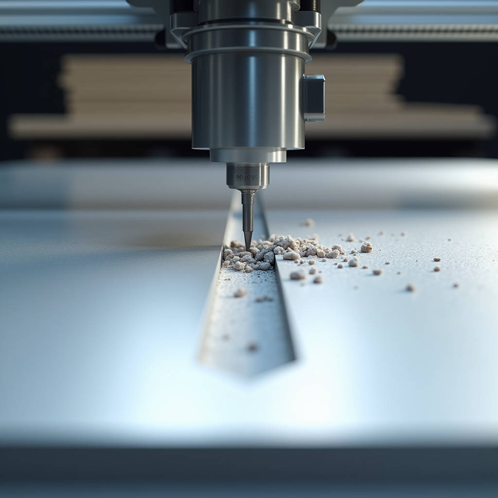
Every solid aluminum cladding panel that arrives on a construction site carries a hidden history—one written not in the visible PVDF-coated surface, but in the grooves, folds, perforations, and edge profiles machined into its reverse side. Aluminum Panel Routing is the subtractive fabrication process that transforms a flat 2.0mm, 2.5mm, or 3.0mm solid aluminum sheet into a dimensionally precise architectural component. Unlike laser cutting or waterjet work, routing uses rotating carbide tooling to remove material along programmed paths, creating V-grooves for folding, recesses for stiffener integration, and open areas for perforated screening. The process determines whether a panel sits dead-flat against its substructure or develops oil-canning distortions visible from street level. For procurement managers and facade contractors, understanding what happens at the routing table separates projects that pass inspection on the first walkthrough from those that generate months of remedial punch-list work.
What Makes Solid Aluminum Routing Fundamentally Different
Routing solid aluminum panels is not the same discipline as routing aluminum composite material. The distinction matters because the toolpath strategies, feed rates, and quality control checkpoints diverge significantly. A solid 2.5mm AA 5005 sheet has no polyethylene core to absorb vibration or forgive a slightly aggressive depth setting. Every pass of the carbide tool engages homogeneous metal from surface to back, which means the operator manages heat buildup, chip evacuation, and tool deflection without the forgiving buffer of a thermoplastic layer.
The material itself sets the parameters. Solid aluminum panels for architectural facades are typically supplied in alloys from the 1xxx, 3xxx, or 5xxx series, with 5052 and 5005 being the most common for their balance of formability and corrosion resistance. Temper matters enormously: an H14 temper routes differently than an H24, with the latter offering slightly better chip-breaking characteristics. A panel ordered in 3.0mm 5005 H24 will behave predictably on a CNC router bed, while the same thickness in a softer temper can gall against the tool flutes, producing a rough groove floor that telegraphs through to the visible face after folding.
Tooling Selection and Its Direct Impact on Edge Quality
The difference between a clean routable edge and one that requires secondary hand-finishing comes down to three tooling decisions made before the spindle ever spins up. Solid carbide V-groove bits dominate architectural aluminum routing because they maintain edge sharpness through hundreds of linear meters of cutting. The included angle—typically 90°, 110°, or 135°—determines the fold geometry. A 90° V-bit produces a tight internal corner after folding, suitable for cassette panel returns where the reveal must stay minimal. A 135° bit leaves more material at the groove root, which increases the minimum achievable bend radius but reduces the risk of stress cracking along the fold line.
Tool diameter and flute count are equally critical. Single-flute upcut bits excel at chip evacuation in deep groove work, clearing the aluminum swarf that would otherwise pack into the cut channel and score the groove walls. Two-flute bits provide better surface finish at the cost of more conservative feed rates. The practical rule observed across high-volume fabrication shops: if the groove depth exceeds 1.5mm in solid aluminum, a single-flute tool with a polished flute face reduces the incidence of built-up edge—the phenomenon where aluminum adheres to the cutting edge and destroys surface finish within seconds.
Coating technology on the tool itself has advanced significantly. Uncoated micrograin carbide remains the cost-effective workhorse, but TiAlN (titanium aluminum nitride) coated tools extend life by a factor of three to four when routing the higher-silicon-content alloys occasionally specified for decorative applications. The coating's thermal barrier properties keep heat in the chip rather than the tool body, which is particularly relevant when routing panels that will subsequently receive a PVDF spray coating—any heat-affected zone near the groove can alter the oxide layer and affect coating adhesion.
CNC Programming Parameters That Determine Panel Flatness
Routing depth control is the single most consequential variable in solid aluminum panel fabrication. The goal is to leave a consistent web of material—typically 0.3mm to 0.5mm—at the base of the V-groove. This residual thickness becomes the hinge that allows the panel to fold while maintaining the dimensional relationship between the face and the return leg. If the router cuts too deep, the hinge tears during folding. Too shallow, and the fold radius becomes inconsistent, pulling the panel out of plane.
The following table summarizes the recommended routing parameters for solid aluminum panels across common thicknesses, based on production data from high-volume architectural fabrication facilities:
| Panel Thickness | Alloy & Temper | Recommended Groove Depth | Residual Web | V-Bit Angle | Spindle Speed (RPM) | Feed Rate (mm/min) |
|---|---|---|---|---|---|---|
| 2.0mm | 5005 H24 | 1.65 - 1.70mm | 0.30 - 0.35mm | 90° | 18,000 - 20,000 | 2,000 - 2,500 |
| 2.5mm | 5005 H24 | 2.10 - 2.20mm | 0.30 - 0.40mm | 90° or 110° | 16,000 - 18,000 | 1,800 - 2,200 |
| 3.0mm | 5005 H24 | 2.55 - 2.65mm | 0.35 - 0.45mm | 110° or 135° | 14,000 - 16,000 | 1,500 - 1,800 |
| 3.0mm | 5052 H32 | 2.50 - 2.60mm | 0.40 - 0.50mm | 110° | 14,000 - 16,000 | 1,400 - 1,700 |
These figures assume a rigid vacuum-bed fixturing system and properly maintained spindle runout below 0.01mm. Shops running older equipment with worn spindle bearings should reduce feed rates by 15-20% to compensate for the additional tool deflection that worn spindles introduce.
Perforated Panel Routing: Managing Heat and Distortion
Perforated solid aluminum panels present a distinct routing challenge. When a CNC router cuts hundreds of holes or slots into a 2.5mm sheet, the cumulative heat input can warp the panel beyond acceptable flatness tolerances—sometimes before the part even leaves the machine bed. The mechanism is straightforward: each hole removes material that previously contributed to the panel's stiffness, and the localized heating during cutting creates thermal expansion that, when repeated across a grid pattern, can permanently distort the sheet.
The countermeasure is a combination of programming strategy and coolant application. Peck-drilling cycles—where the tool retracts partially after each plunge to allow chip clearance and cooling—produce better results than single-pass plunges. For slot patterns, climb-milling toolpaths (where the cutter rotates in the same direction as the feed) reduce the heat transferred into the workpiece compared to conventional milling. A mist coolant system delivering a fine ethanol-based lubricant at the tool-workpiece interface can drop the steady-state cutting temperature by 40-60°C, which is often the difference between a panel that measures flat within 0.5mm across a 1200mm span and one that exhibits visible oil-canning.
Futeng® has observed in its own fabrication workflows that perforated panels with an open area exceeding 30% benefit from being routed on a vacuum table with zone control—activating vacuum only in the areas immediately surrounding the current toolpath. This prevents the partially routed panel from being pulled into the vacuum plenum as its stiffness decreases with each cut.
Edge Profiling and Stiffener Integration
Beyond V-grooving, Aluminum Panel Routing encompasses the edge profiling operations that prepare a panel for its connection to the building's substructure. Return legs—the folded edges that create the panel's depth—require clean, square trimmed edges that seat flush against aluminum extrusions or steel subframes. A poorly routed edge with burrs or inconsistent width creates a gap that invites water ingress and compromises the rainscreen principle.
Stiffener integration is another routing-intensive operation. Solid aluminum panels spanning more than 600mm in any direction typically require aluminum stiffeners bonded or mechanically fixed to the reverse side. The routing operation here cuts shallow channels—often 1.0mm to 1.5mm deep and 20mm to 30mm wide—into which the stiffener profile sits. These channels must be positioned precisely relative to the panel's fold lines; a 2mm positional error can mean the stiffener interferes with the substructure bracket during installation.
The AAMA 508 standard for structural silicone glazing references the importance of clean, contamination-free surfaces for adhesive bonding. For stiffeners attached with structural silicone, the routed channel must be free of cutting fluid residue and aluminum oxide dust. Shops that run a secondary cleaning pass—a light skim cut at 0.05mm depth with a fresh tool immediately before the bonding operation—report significantly fewer adhesive failures in cyclic wind load testing.
Quality Control: What to Inspect Before the Panel Leaves the Router Table
Routing quality manifests in three measurable outputs: groove depth consistency, edge condition, and dimensional accuracy. Groove depth is verified with a dial indicator or digital depth gauge at multiple points along each fold line. A tolerance of ±0.05mm is achievable on well-maintained equipment; anything beyond ±0.10mm warrants investigation into vacuum hold-down integrity or spindle tram errors.
Edge condition is assessed visually and tactilely. A properly routed solid aluminum edge should show no burr exceeding 0.1mm, no chatter marks (which indicate resonance between the tool and the workpiece), and no discoloration from heat. Discoloration is particularly critical because it signals temperatures that may have altered the aluminum's temper locally. The ASTM B209 standard for aluminum sheet and plate specifies that localized heating above 200°C can reduce tensile strength in H24 temper material by 10-15%, which may not be recoverable through any downstream process.
"The most expensive routing mistake in architectural aluminum is not a scrapped panel—it's a panel that passes visual inspection but carries residual stress into the building envelope, where it manifests as oil-canning six months after installation."
Dimensional accuracy is verified against the shop drawing using a calibrated coordinate measuring system or, for smaller shops, a precision tape measure and square. The critical dimensions are the face dimensions (which determine joint widths between adjacent panels), the return leg depth (which sets the cavity depth for the rainscreen), and the positions of any routed openings for windows, louvers, or penetrations. A 1.5mm error on a panel face dimension compounds across a 20-panel elevation to a 30mm cumulative error—enough to visibly misalign joints and trigger a rejection from the architect's site inspector.
Production Workflow Integration
Routing does not exist in isolation. In a well-organized fabrication facility, the routing station sits between the guillotine shear (which cuts blanks from full-size sheets) and the folding station (where routed panels are bent to their final geometry). The sequencing matters because routing generates heat and removes material, both of which can relieve residual stresses locked into the sheet during the rolling process at the aluminum mill.
Some fabricators have adopted a two-stage routing approach for large panels exceeding 2.4 meters in any dimension. The first stage roughs out the grooves to within 0.2mm of final depth using a larger-diameter tool at higher feed rates. The panel is then allowed to rest for 15-20 minutes to thermally stabilize before a finishing pass brings the grooves to final depth with a sharp, smaller-diameter tool. This approach adds cycle time but measurably improves flatness in panels that will be installed on high-visibility facades with stringent specular reflectance requirements.
The ISO 2768-1 general tolerance standard provides a useful reference framework for routing tolerances, though most architectural specifications will define tighter requirements specific to the project. For reference, the Aluminum Association's Designation System for Aluminum Finishes clarifies that mechanical finishing operations—including routing—fall under the M-series designations, distinct from chemical or electrochemical finishes.
Common Routing Defects and Their Root Causes
When a routed panel exhibits defects, the troubleshooting process should follow a systematic path rather than defaulting to "reduce the feed rate." The most frequently encountered issues in solid aluminum panel routing include:
Groove width inconsistency: This typically traces to spindle runout or tool holder contamination. A dial indicator measurement at the tool tip should read less than 0.01mm total indicated runout. Values above 0.02mm produce visible width variation along the groove. The fix is often as simple as cleaning the tool holder taper with a lint-free wipe and re-torquing to the manufacturer's specification.
Burr formation along the groove edge: While some burr is inevitable in aluminum machining, excessive burr indicates either a dull tool or incorrect chip load. The chip load—the thickness of material removed per tooth per revolution—should stay between 0.05mm and 0.10mm for finishing passes in architectural aluminum. Below 0.03mm, the tool rubs rather than cuts, work-hardening the surface and generating a stubborn burr. Above 0.15mm, the cutting forces can deflect the tool and degrade surface finish.
Groove bottom roughness: A rough groove floor that prevents clean folding usually results from chip recutting—where aluminum chips are not evacuated from the cut zone and are crushed between the tool and the workpiece. Improving dust extraction airflow, switching to a tool with more aggressive chip-breaking geometry, or adding a compressed air blast directed at the cut zone can resolve this.
Panel lifting from the vacuum table: This is particularly common with thinner 2.0mm panels. As the router removes material, internal stresses in the sheet can cause it to curl upward, breaking the vacuum seal. The solution involves either increasing the vacuum pump capacity, adding mechanical clamps at the panel perimeter, or specifying panel blanks with tighter flatness tolerances from the mill.
Material Specifications and Standards Reference
Procurement specifications for routed solid aluminum panels should reference the governing standards that ensure the material entering the routing process is fit for purpose. The key documents include:
- ASTM B209 — Standard Specification for Aluminum and Aluminum-Alloy Sheet and Plate. This defines the chemical composition, mechanical properties, and dimensional tolerances for the raw sheet material before fabrication.
- EN 485 — The European equivalent covering aluminum sheet, strip, and plate for general engineering applications, with Part 2 addressing mechanical properties and Part 3 covering tolerances on dimensions and form.
- AAMA 2605 — Voluntary Specification for High Performance Organic Coatings on Architectural Aluminum Extrusions and Panels. While focused on coating performance, the substrate preparation requirements in Section 5.3 are directly relevant to routed surfaces that will receive a PVDF or FEVE coating.
- BS EN 12206 — Paints and varnishes for coating of aluminum and aluminum alloys for architectural purposes, which provides the European framework for coating specification on routed and formed panels.
The ASTM B209 standard is particularly relevant because it defines the flatness tolerances for the incoming sheet. A panel blank that meets the standard's flatness requirement of 6mm deviation per 1200mm length will route more predictably than one that barely passes. Shops that invest in incoming material inspection—checking thickness, flatness, and temper before the sheet reaches the router—consistently produce higher-quality output with lower scrap rates.
Practical Decision Framework for Project Specifications
When specifying routed solid aluminum panels for a project, the following decision points should be addressed in the fabrication section of the specification:
- Groove geometry: Specify the V-groove angle and the residual web thickness. A 90° groove with 0.3mm web is suitable for sharp-corner cassette panels; a 110° groove with 0.4mm web provides greater folding reliability for larger panels.
- Surface finish post-routing: Define whether routed edges will be visible in the installed condition. If they are, specify a deburring and edge-breaking requirement. If the routed edge is hidden within a folded return, a simpler standard may suffice.
- Inspection sampling rate: For projects with more than 500 panels, a statistical sampling plan based on ISO 2859 (formerly MIL-STD-105) provides a defensible quality assurance framework that balances inspection cost with confidence.
- Coating compatibility: Confirm that any cutting fluids or lubricants used during routing are chemically compatible with the specified PVDF or FEVE coating system. Residues from sulfur-based cutting oils, in particular, can cause coating adhesion failures that only become apparent after 12-18 months of weathering.
For projects in coastal or high-corrosion environments, the alloy selection becomes even more critical. The ISO 12944 series on corrosion protection of steel structures provides a useful corrosivity classification framework that can inform aluminum alloy and coating system selection, even though the standard itself addresses steel. A C4 or C5 corrosivity environment typically drives specification toward 5005 or 5052 alloys with minimum 3.0mm thickness and a three-coat PVDF system.
Aluminum Panel Routing, when executed with proper tooling, programmed parameters, and quality control discipline, produces panels that install efficiently and perform reliably across decades of service. The process rewards attention to detail at every stage—from incoming material inspection through to the final dimensional check before the panel moves to folding. For procurement teams and facade contractors evaluating fabrication partners, the routing capability of a facility is one of the most reliable indicators of the quality that will ultimately appear on the building.