Aluminum Panel Shearing Technical Guide for Solid Cladding Fabrication and Facade Quality
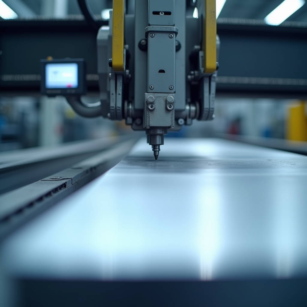
Aluminum Panel Shearing represents one of the most consequential yet frequently underestimated stages in solid aluminium cladding fabrication. The way a 2.0mm, 2.5mm, or 3.0mm solid aluminium sheet is cut determines not only dimensional accuracy but also the long-term integrity of the installed facade. A poorly executed shear introduces micro-cracks along the cut edge, creates burrs that compromise PVDF coating adhesion, and can generate residual stress that manifests as oil-canning months after installation. For curtain wall contractors and facade engineers, understanding the interplay between shear blade clearance, alloy temper, and material thickness is not optional — it is the difference between a panel that fits perfectly on site and one that requires costly rework. This article examines the technical realities of Aluminum Panel Shearing within the context of architectural cladding production, focusing on how shear parameters must be calibrated to specific aluminium alloys and coating systems used in modern building envelopes.
Why Shear Quality Dictates Facade Performance
When a solid aluminium cladding panel arrives on site, the first thing an installer checks is whether the edges are clean and the dimensions match the shop drawings. What they are actually evaluating is the quality of the shearing operation performed at the fabrication facility. A shear cut that deviates by even 0.5mm across a 3-meter panel length creates cumulative alignment problems across a curtain wall grid. More critically, the condition of the sheared edge directly affects coating performance. PVDF fluoropolymer coatings — typically applied at 25-35 microns for architectural applications per AAMA 2605 — require a properly prepared substrate. A burred or rough shear edge creates a stress riser where coating thickness becomes inconsistent, opening a pathway for moisture ingress and eventual filiform corrosion.
The mechanical reality is straightforward: Aluminum Panel Shearing involves a guillotine-type action where an upper blade descends past a fixed lower blade, creating a controlled fracture through the material. What separates professional architectural fabrication from general sheet metal work is the precision with which blade clearance is set relative to material thickness and alloy grade. For solid aluminium panels in the 2.0mm to 3.0mm range, blade clearance typically needs to be maintained at 5-8% of material thickness. A 3.0mm 5052-H32 panel, for example, requires approximately 0.15mm to 0.24mm of blade clearance. Too tight, and the cut requires excessive force, potentially deforming the panel. Too loose, and the material tears rather than shears, producing a ragged edge with significant burr formation.
Alloy Selection and Its Impact on Shear Behavior
Not all aluminium alloys respond to shearing the same way. The three alloys most commonly specified for architectural cladding — 1100, 3003, and 5052 — each exhibit distinct shear characteristics that fabricators must account for. The differences stem from their chemical composition and work-hardening behavior, which directly influence how the material fractures under the shear blade.
Alloy 1100, being commercially pure aluminium with 99% minimum aluminium content, offers the easiest shearing experience. Its low yield strength of approximately 34 MPa in the H14 temper means blade wear is minimal, and cut edges are generally clean. However, this same softness makes 1100 panels more susceptible to handling damage during fabrication, and the material's lower tensile strength limits its use to interior or low-wind-load applications.
Alloy 3003, containing approximately 1.2% manganese, provides a practical middle ground. With yield strength around 145 MPa in H14 temper, it shears cleanly with standard tool steel blades and offers sufficient strength for most commercial facade applications. The manganese content improves corrosion resistance without making the material excessively hard on tooling. This is why 3003 remains the workhorse alloy for mid-range architectural cladding projects globally.
Alloy 5052, with 2.5% magnesium content, delivers the highest strength of the three — approximately 193 MPa yield in H32 temper — but presents the most demanding shearing conditions. The magnesium content increases the material's tendency to adhere to blade surfaces, a phenomenon known as galling. Without proper blade lubrication and slightly wider clearance settings, 5052 panels can develop a built-up edge on the shear blade that progressively degrades cut quality across a production run. For coastal and high-corrosion environments where 5052 is specified for its superior salt-spray resistance, fabricators must invest in higher-grade blade materials and more frequent maintenance intervals.
| Alloy & Temper | Yield Strength (MPa) | Recommended Blade Clearance (% of thickness) | Shear Force @ 3.0mm (kN/m) | Edge Quality Rating | Typical Cladding Application |
|---|---|---|---|---|---|
| 1100-H14 | 34 | 4.5 - 6.0% | ~95 | Excellent | Interior wall panels, soffits |
| 3003-H14 | 145 | 5.5 - 7.0% | ~210 | Very Good | General exterior cladding |
| 5052-H32 | 193 | 6.5 - 8.5% | ~280 | Good (requires optimized setup) | Coastal facades, high-corrosion zones |
| 3004-H34 | 200 | 6.0 - 8.0% | ~265 | Good | High-strength structural panels |
| 5005-H34 | 138 | 5.5 - 7.0% | ~200 | Very Good | Anodized architectural panels |
Blade Metallurgy and Tooling Economics
The shear blade is the single most expensive consumable in a cladding fabrication operation, and its material composition directly determines cut quality over time. Standard shear blades are manufactured from high-carbon, high-chromium tool steels such as AISI D2 or equivalent grades, hardened to 58-62 HRC. For architectural aluminium shearing, D2 provides an acceptable balance of wear resistance and toughness. However, when processing 5052 alloy or running high-volume production of 3003 panels, the economic case for upgrading to powder metallurgy (PM) tool steels or even tungsten carbide-edged blades becomes compelling.
Consider a typical fabrication run: a mid-sized curtain wall project might require 2,000 solid aluminium panels, each requiring four shear cuts. That is 8,000 individual shearing operations. With D2 blades cutting 3003-H14 at 2.5mm thickness, blade regrinding is typically required after approximately 15,000-20,000 linear meters of cut. If the same blades are used on 5052-H32, that interval drops to roughly 8,000-12,000 meters due to the abrasive nature of the magnesium-containing alloy. PM tool steels, while costing 2-3 times more upfront, can extend these intervals by 40-60%, reducing machine downtime and maintaining consistent edge quality across the entire production batch.
Blade edge radius is another parameter that receives insufficient attention. A freshly sharpened blade has an edge radius of approximately 0.01-0.02mm. As the blade wears, this radius increases. When it exceeds approximately 0.05mm, the shearing action transitions from a clean cut toward a tearing action, producing the burrs and edge deformation that coating inspectors flag. Progressive fabricators implement blade inspection protocols that measure edge radius at regular intervals — typically every 5,000 cuts — using optical comparators or portable profilometers. This data-driven approach prevents the common scenario where a fabricator only discovers edge quality issues when the coating line reports adhesion failures.
Shear-Induced Residual Stress and Panel Flatness
One of the least visible but most consequential effects of Aluminum Panel Shearing is the introduction of residual stress along the cut edge. When the shear blade penetrates the aluminium sheet, the material undergoes severe plastic deformation in a narrow zone adjacent to the cut line. This deformation zone, typically extending 2-5mm from the edge depending on material thickness and temper, contains locked-in stresses that can cause the panel to deviate from flatness after installation.
The mechanism works as follows: during shearing, the upper blade compresses the material surface while the lower blade supports the underside. This asymmetric loading creates a bending moment that rotates the material slightly before fracture occurs. The rotation introduces tensile stress on one face and compressive stress on the opposite face. After the cut is complete, these stresses partially relax, but a residual stress gradient remains through the panel thickness near the edge. For a 3.0mm 5052-H32 panel, this residual stress can reach 30-50 MPa in the affected zone.
When the panel is subsequently bent or formed — for example, when creating return legs or stiffener grooves — these residual stresses interact with the forming stresses in ways that are difficult to predict without finite element analysis. The practical consequence is that panels that measured flat on the fabrication table may develop visible waviness or oil-canning after being installed on the building. This is particularly problematic for large-format panels exceeding 1.2 meters in width, where the cumulative effect of shear-edge stresses across multiple edges can produce center deflection exceeding 2-3mm.
Mitigation strategies include stress-relief heat treatment after shearing — though this is rarely economical for architectural volumes — and, more practically, adjusting the shear blade rake angle. A rake angle of 1.5-2.5 degrees, rather than a perfectly parallel blade setup, reduces the peak shearing force and distributes the deformation more gradually along the cut length, resulting in lower residual stress levels. Some advanced CNC shearing systems now incorporate variable rake angle control, automatically adjusting based on material grade and thickness inputs.
Shearing vs. Alternative Cutting Methods: When Precision Matters
While shearing remains the dominant production method for cutting solid aluminium cladding panels to size, alternative technologies have emerged that offer distinct advantages for specific applications. Understanding where each method fits in the fabrication workflow helps project managers make informed decisions about quality, cost, and lead time.
CNC routing, using carbide or diamond-coated bits, produces edges with virtually no burr and minimal heat-affected zone. The trade-off is speed: a CNC router cutting a 3-meter panel edge operates at approximately 2-5 meters per minute, compared to a shear that completes the same cut in under one second. For projects requiring complex geometries — radiused corners, notches, or cutouts for penetrations — routing is often the only viable option. However, for the straight-line cuts that constitute 80-90% of cladding panel perimeter work, shearing remains 5-10 times faster and significantly more cost-effective.
Laser cutting of aluminium has advanced considerably, with fiber laser systems now capable of cutting 3.0mm aluminium at speeds approaching 10 meters per minute. The edge quality is excellent, with a heat-affected zone typically under 0.1mm. However, the capital cost of industrial laser systems suitable for architectural panel dimensions remains prohibitive for most cladding fabricators, and the nitrogen assist gas consumption adds significant operating cost. Laser cutting finds its niche in perforated panel production and intricate decorative work rather than primary panel sizing.
Waterjet cutting offers the unique advantage of zero heat input, eliminating any concern about thermal effects on the aluminium microstructure or pre-applied coatings. For projects where panels are being cut after PVDF coating — a practice generally discouraged but sometimes unavoidable for field modifications — waterjet is the only method that preserves coating integrity at the cut edge. The downside is slower cutting speeds and higher operating costs compared to shearing.
For the vast majority of architectural cladding projects, the practical workflow involves shearing for primary sizing, followed by CNC routing for any required cutouts, notches, or complex perimeter features. This hybrid approach maximizes the efficiency of shearing while leveraging the precision of routing where it adds genuine value. Fabricators like Futeng® have optimized this two-stage process, using precision shear lines for bulk panel sizing and dedicated CNC work cells for feature machining, achieving dimensional tolerances of ±0.3mm on finished panels.
Coating Compatibility and Edge Treatment After Shearing
The relationship between shearing and coating performance is direct and measurable. PVDF and FEVE fluoropolymer coatings, which dominate the high-end architectural cladding market, are applied as liquid systems that flow over the panel surface and edge. A sheared edge with burrs, micro-cracks, or excessive roughness creates three distinct coating failure risks.
First, burrs act as high points where coating thickness is reduced. A burr projecting 0.1mm above the panel surface will receive only 10-15 microns of the specified 30-micron coating thickness, well below the minimum required for long-term UV and moisture protection. Second, micro-cracks at the shear edge — typically 0.05-0.2mm deep — can trap air during the coating application process, creating voids that expand and contract with thermal cycling and eventually cause coating delamination. Third, the increased surface roughness of a poorly sheared edge provides more surface area for moisture and contaminants to adhere, accelerating the corrosion process at the panel perimeter.
The standard remediation is edge deburring, performed either manually with abrasive pads or mechanically with rotating brush systems integrated into the production line. For architectural panels receiving PVDF coating, the edge condition after deburring should meet a surface roughness (Ra) of 3.2-6.3 microns, as measured per ISO 4287. This provides sufficient mechanical key for coating adhesion without creating the deep valleys that compromise coverage.
An often-overlooked step is edge cleaning after deburring. The deburring process generates fine aluminium particles that, if not removed, become embedded in the coating during application. These particles create localized discontinuities that appear as pinhole defects after curing. A proper cleaning protocol involves compressed air blow-off followed by solvent wiping with isopropyl alcohol or MEK, performed immediately before the panels enter the coating line pretreatment stage.
Shear Machine Selection for Architectural Fabrication
Selecting the right shear for architectural aluminium panel production requires balancing capacity, precision, and operational flexibility. The key machine parameters that differentiate professional-grade equipment from general-purpose sheet metal shears include:
Cutting length capacity: Architectural panels commonly range from 1.0 to 4.0 meters in length. A shear with 4.2-meter capacity covers the vast majority of cladding panel dimensions without requiring panel repositioning. Machines with shorter beds force operators to reposition panels for long cuts, introducing alignment errors that accumulate across the panel perimeter.
Back gauge accuracy: CNC-controlled back gauges with servo-driven positioning achieve repeatability of ±0.05mm, essential for maintaining consistent panel dimensions across a production batch. Manual back gauges, while less expensive, introduce operator-dependent variability that can exceed ±0.5mm — unacceptable for curtain wall applications where panel-to-panel gaps are specified at 15-20mm.
Hydraulic vs. mechanical drive: Hydraulic shears provide variable speed control and consistent force throughout the stroke, making them better suited for the thicker 3.0mm panels used in high-wind-load applications. Mechanical shears, while faster, deliver peak force only at a specific point in the stroke and can stall on thicker or harder alloys. For architectural fabrication handling multiple alloys and thicknesses, hydraulic systems offer the necessary flexibility.
Blade gap adjustment: Manual blade gap adjustment requires operator skill and time. CNC-controlled automatic gap adjustment, linked to the machine's material database, sets the optimal clearance based on the specific alloy and thickness being processed. This eliminates the most common source of shear quality variation in production environments.
Standards such as ISO 9013 provide classification systems for thermal cutting quality, but for mechanical shearing of aluminium, the relevant guidance comes from the Aluminum Association design manuals and ASTM E290 for bend testing of ductility. These references establish the baseline expectations for edge condition and material integrity after shearing operations.
Production Workflow: Integrating Shearing into the Fabrication Sequence
The position of Aluminum Panel Shearing within the overall fabrication sequence has significant implications for both efficiency and quality. Three common workflow configurations are observed across the industry, each with distinct advantages and limitations.
Pre-coating shear approach: Panels are sheared to final size before coating. This is the conventional workflow and offers the advantage that coating covers the entire panel perimeter, providing maximum edge protection. The risk is that handling during coating — hanging, transport through the coating line, curing — can introduce minor edge damage that is difficult to repair without stripping and recoating the entire panel. This approach works best when the coating line is integrated with the fabrication facility, minimizing handling between operations.
Post-coating shear approach: Panels are coated in larger sheet formats and sheared to final size afterward. This approach is common when coating is outsourced to a separate facility. The advantage is that any handling damage during coating is trimmed away. The disadvantage is that the sheared edge is uncoated, creating a potential corrosion initiation point. This approach requires edge touch-up with air-dry fluoropolymer paint, which never matches the quality of factory-applied baked coating.
Hybrid approach: Panels are sheared to within 10-15mm of final size, coated, and then trimmed to exact dimensions. This minimizes the uncoated edge area while capturing most of the handling efficiency benefits. The trim cut removes only a small amount of coated material, and the resulting bare edge is narrow enough that field touch-up provides adequate protection for most environments. For projects in aggressive coastal or industrial atmospheres, the pre-coating shear approach remains the safer choice.
The Aluminum Anodizers Council provides guidance on edge treatment for anodized panels, while AAMA 2605 governs the performance requirements for organic coatings on architectural aluminium. Both standards emphasize that edge condition is integral to overall coating system performance, not an afterthought.
Quality Control: Measuring and Verifying Shear Quality
Implementing a systematic quality control program for sheared aluminium panels requires defined acceptance criteria and measurement methods. The following parameters should be checked on a sampling basis, with frequency determined by production volume and the criticality of the project.
Dimensional accuracy: Length and width measured with calibrated steel tape or digital calipers, referenced to the panel's centerline to avoid errors from out-of-square conditions. Tolerance: ±0.5mm for panels up to 2 meters, ±0.8mm for panels 2-4 meters.
Squareness: Measured by comparing diagonal dimensions. The difference between diagonals should not exceed 1.0mm for panels up to 2 meters, and 1.5mm for larger panels. Out-of-square panels create cumulative alignment problems in curtain wall grids.
Edge burr height: Measured with a dial indicator or optical comparator. Maximum acceptable burr height is 0.05mm for panels receiving PVDF coating, as burrs above this threshold create coating thickness deficiencies.
Edge straightness: Checked with a straightedge and feeler gauge along the full cut length. Deviation should not exceed 0.3mm per meter of cut length. Waviness in the cut edge indicates blade wear or improper clearance settings.
Surface condition: Visual inspection under adequate lighting for scratches, gouges, or surface deformation adjacent to the cut line. Any surface damage extending more than 3mm from the edge should trigger rejection, as it will be visible on the installed panel.
Documentation of these measurements provides traceability and supports continuous improvement of shear parameters. When a pattern of edge quality issues emerges, the data points directly to the root cause — blade wear, clearance adjustment, or material variation — rather than requiring guesswork.
Practical Recommendations for Project Specifications
For architects and specifiers writing performance specifications for aluminium cladding, the following language captures the essential requirements for Aluminum Panel Shearing quality without being prescriptive about fabrication methods:
Fabricated panel edges shall be clean, free of burrs exceeding 0.05mm, and free of visible cracks or delamination. Dimensional tolerance shall be ±0.5mm for panels up to 2,000mm in any dimension. Panel squareness shall be verified by diagonal measurement, with maximum deviation of 1.0mm between diagonals. Edge condition after shearing shall be suitable to receive the specified coating system, with surface roughness not exceeding Ra 6.3 microns in the zone within 10mm of the cut edge.
For contractors procuring fabricated panels, the key takeaway is that shear quality cannot be inspected into a panel after the fact — it must be built into the fabrication process. Visiting the fabrication facility, observing the shear setup, and reviewing quality control records provides more meaningful assurance than any incoming inspection procedure performed on the construction site.
The technical reality of modern architectural aluminium fabrication is that Aluminum Panel Shearing, while appearing straightforward, demands precise control of multiple interdependent variables. Blade clearance, alloy temper, tooling condition, and workflow sequencing all interact to determine whether the finished panel meets the demanding standards of contemporary curtain wall construction. When these variables are properly managed, shearing delivers the combination of speed, accuracy, and cost-effectiveness that makes solid aluminium cladding a practical choice for projects ranging from commercial office towers to institutional buildings. The difference between a successful facade installation and one plagued by fit-up problems and coating failures often traces back to decisions made at the shear.