Aluminum Panel CNC Punching Tooling Strategies and Flatness Control for Solid Facade Cladding
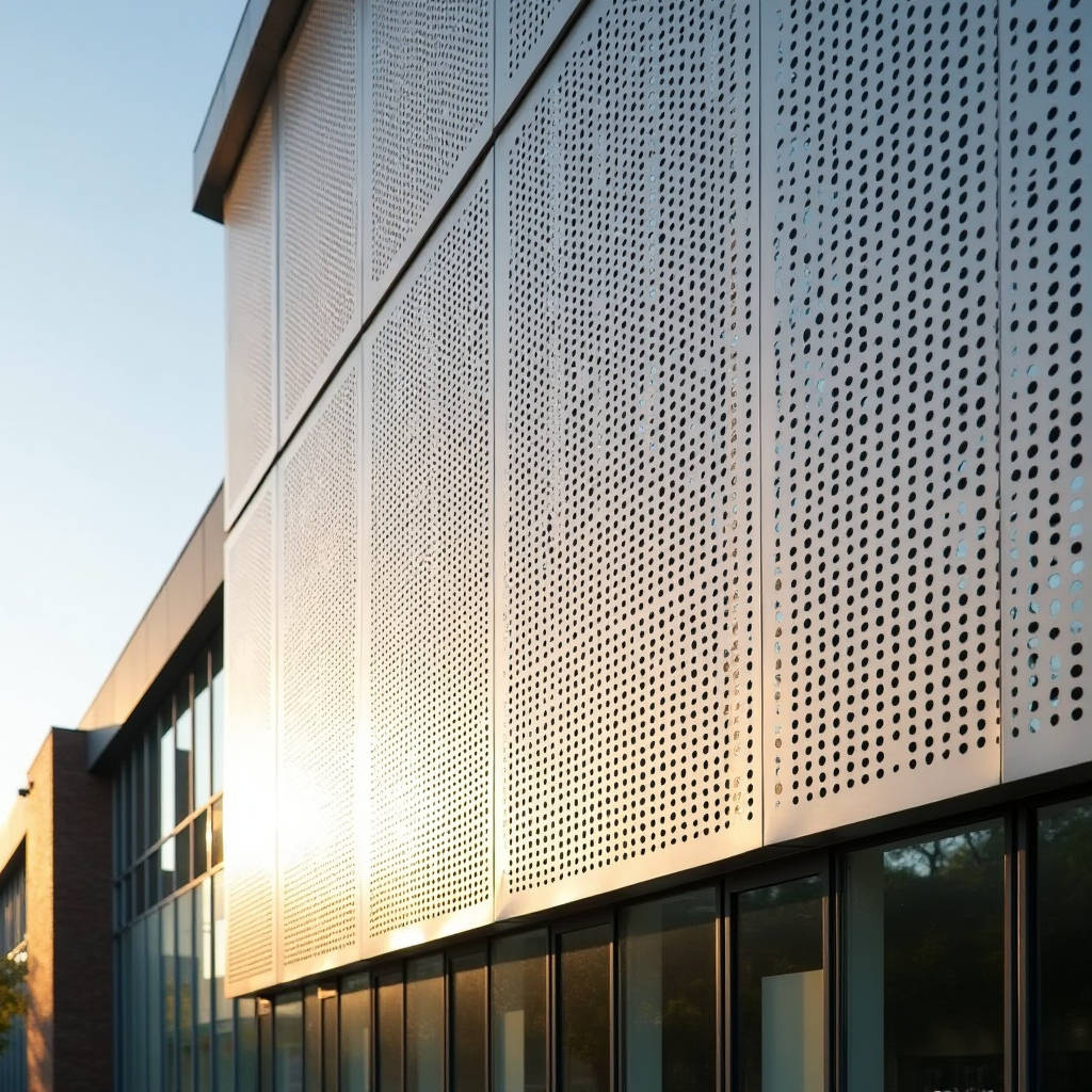
When a facade contractor in Dubai asks whether your shop can hold ±0.15mm tolerance across 2,800 punched holes on a 3.0mm solid aluminum sheet, there is exactly one process that answers the question: Aluminum Panel CNC Punching. This is not laser cutting. It is not waterjet. It is a high-speed, multi-tool turret press operation that punches, forms, and patterns solid aluminum cladding panels with repeatability that manual fabrication cannot touch. The conversation around CNC punching for architectural aluminum has shifted in the last three years. It is no longer about whether the machine can make holes. It is about how many holes per minute, at what edge quality, with what tooling strategy, and whether the grain direction of the aluminum sheet will cause micro-cracking around the punch perimeter after 10,000 cycles of thermal expansion on a 40-story tower in Jeddah. This article addresses the specific intersection of CNC punching technology and solid aluminum facade panels: tooling selection, hole geometry limits, flatness preservation, coating compatibility, and the cost-speed-quality triangle that procurement managers need to understand before issuing a purchase order.
What CNC Punching Actually Means for Solid Aluminum Facade Panels
Aluminum Panel CNC Punching is a subtractive sheet metal fabrication process where a computer-controlled turret press drives hardened tool steel punches through solid aluminum sheet at programmed coordinates. The turret holds 20 to 60 tool stations, each carrying a different punch-and-die set. The machine positions the sheet using pneumatic or servo-driven clamps on a Cartesian X-Y table, rotates the turret to the correct tool, and strikes at speeds between 200 and 900 hits per minute depending on material thickness and hole size.
For solid aluminum cladding panels — typically 2.0mm, 2.5mm, or 3.0mm thick 3003-H14 or 5052-H32 alloy — the process is fundamentally different from punching mild steel. Aluminum is softer, more ductile, and prone to galling on tool surfaces. The die clearance must be tighter. The punch speed must be controlled. The lubrication strategy matters. Get any of these wrong and you will see burr formation, die-side material pull-down, or worse: stress fractures that propagate through the PVDF coating six months after installation.
The architectural market demands CNC punching for three specific applications: perforated sunshade panels, acoustic cladding with micro-hole patterns, and decorative facade screens with custom geometric cutouts. Each application pushes different limits of the process. Sunshade panels need large open areas (40-60%) with structural integrity. Acoustic panels need thousands of sub-3mm holes in tight staggered patterns. Decorative screens need complex shapes — triangles, hexagons, custom logos — that require specialized tooling and sometimes multi-hit forming sequences.
Tooling Strategy: The Difference Between a Clean Hole and a Rejected Panel
Tooling selection for Aluminum Panel CNC Punching is not a one-size-fits-all decision. The punch-to-die clearance, punch geometry, coating, and tool steel grade all interact with the specific aluminum alloy being processed. Standard rule of thumb: die clearance for aluminum should be 8-12% of material thickness, compared to 15-20% for mild steel. For a 2.5mm 3003-H14 panel, that means a clearance of 0.20mm to 0.30mm between punch and die. Too tight and you get excessive tool wear and secondary shear. Too loose and you get rollover, burr, and dimensional inaccuracy.
Punch tip geometry matters enormously. A standard flat punch with a slight shear angle (1-3 degrees) reduces punching force by 30-40% compared to a dead-flat punch. This is critical when punching thick aluminum because lower tonnage means less panel distortion. For architectural panels where flatness is non-negotiable — a 3.0mm panel that bows more than 0.5mm across a 1,200mm span will be rejected on site — shear-angle tooling is standard practice.
Tool coatings have evolved. Titanium nitride (TiN) coated punches were the industry standard for a decade. Today, aluminum-specific coatings like AlCrN (aluminum chromium nitride) and diamond-like carbon (DLC) coatings reduce galling dramatically. Galling is the enemy: aluminum material transfers to the punch surface, builds up, and tears the panel surface on subsequent hits. A shop running DLC-coated tooling can punch 50,000 hits between tool maintenance intervals on 5052 alloy, versus 15,000-20,000 with uncoated M2 tool steel.
Common Tooling Configurations for Architectural Panels
- Round punches — diameters from 2.0mm to 120mm, used for perforated sunshade and acoustic panels. The most common tool in any turret.
- Shape punches — square, rectangular, hexagonal, triangular, and oblong. Custom shapes require custom tooling with lead times of 3-6 weeks from tooling suppliers.
- Cluster tools — multiple punches in a single tool holder, enabling simultaneous punching of hole groups. Reduces cycle time by 40-60% on repetitive patterns.
- Forming tools — louver punches, bridge lances, and dimple dies that create 3D features in a single hit. Used for ventilation panels and textured facade elements.
- Parting tools — shear blades for cutting panels to final size within the punching cycle, eliminating a secondary shearing operation.
Hole Geometry Limits and Design Rules for Architects
Architects frequently specify perforation patterns that look beautiful in Rhino or Grasshopper but push against the physical limits of CNC punching. The most common conflict: hole diameter versus material thickness. The minimum hole diameter that can be reliably punched in solid aluminum is equal to the material thickness. For a 2.5mm panel, do not specify holes smaller than 2.5mm diameter. Below this ratio, the punch becomes a needle that deflects, breaks, or produces unacceptable hole quality.
Web width — the distance between adjacent hole edges — has a hard minimum of 1.0x material thickness, and a practical minimum of 1.5x for architectural panels that must survive handling, transport, and installation without tearing. A panel with 2.0mm webs between 8mm holes in 2.5mm aluminum will arrive at the jobsite with warped webs and micro-cracks visible under raking light. The fix is either thicker material, larger web widths, or both.
Open area percentage is the metric that drives both aesthetic performance and structural behavior. Here is a practical reference table based on real fabrication experience with 3003-H14 solid aluminum panels:
| Hole Diameter (mm) | Staggered Pitch (mm) | Open Area (%) | Min. Web Width (mm) | Recommended Min. Panel Thickness (mm) |
|---|---|---|---|---|
| 3.0 | 5.0 | 32.6 | 2.0 | 2.0 |
| 5.0 | 8.0 | 35.4 | 3.0 | 2.0 |
| 8.0 | 12.0 | 40.3 | 4.0 | 2.5 |
| 10.0 | 15.0 | 40.3 | 5.0 | 2.5 |
| 15.0 | 22.0 | 42.1 | 7.0 | 3.0 |
| 20.0 | 28.0 | 46.2 | 8.0 | 3.0 |
These numbers assume a standard 60-degree staggered pattern, which maximizes open area while maintaining structural integrity. Square-grid patterns reduce open area by approximately 13% at the same pitch and are generally less efficient for sunshade applications. The data aligns with guidelines from the ASTM B209 standard for aluminum sheet and plate, though the standard itself does not specify perforation limits — those come from fabrication experience and tooling manufacturer recommendations.
Flatness: The Silent Specification That Kills Projects
Flatness is the most under-specified parameter in Aluminum Panel CNC Punching contracts, and the most common source of disputes between fabricators and general contractors. A solid aluminum sheet starts flat within 0.2mm per 300mm when it leaves the rolling mill. Then you punch 3,000 holes in it. Each punch strike introduces localized plastic deformation. The cumulative stress relief causes the panel to bow, twist, or ripple. The severity depends on hole density, pattern distribution, material thickness, and alloy temper.
The mechanism is straightforward: each punch stroke compresses material around the hole perimeter. The compression zone extends approximately 1.5x the hole diameter outward from the hole edge. When holes are spaced closely, the compression zones overlap and create a tensile stress field across the panel surface. The panel relieves this stress by bowing — typically concave on the punch-entry side, convex on the die-exit side.
Mitigation strategies exist, and they must be built into the fabrication workflow:
- Stress-relief flattening — after punching, panels pass through a roller leveler that applies controlled bending to redistribute internal stresses. This adds $3-6 per square meter to fabrication cost but is essential for panels with open areas above 30%.
- Punch sequence optimization — programming the turret to punch from the panel center outward, rather than edge-to-edge, reduces cumulative distortion by allowing the sheet to expand symmetrically during processing.
- Stiffener rib integration — welding or bonding aluminum stiffener ribs to the rear face of perforated panels before punching. The ribs maintain flatness during fabrication and provide long-term rigidity against wind loads.
- Alloy selection — 5052-H32 alloy exhibits roughly 15% less post-punch distortion than 3003-H14 at the same hole density, due to its higher yield strength (193 MPa vs. 145 MPa). The trade-off is higher material cost and slightly reduced formability.
For reference, a 2.5mm 3003-H14 panel measuring 1,200mm x 2,400mm with 40% open area in a staggered 8mm hole pattern will typically exhibit 3-5mm of bow after punching if no corrective measures are applied. The same panel with roller leveling can achieve flatness within 0.5mm across the full diagonal. That difference is the margin between a panel that installs cleanly and one that requires field shimming, additional fasteners, and angry emails from the site superintendent.
Coating Compatibility: PVDF and the Post-Punch Problem
The standard architectural finish for solid aluminum cladding panels is PVDF (polyvinylidene fluoride) coating, typically applied via spray coating to a dry film thickness of 25-35 microns, conforming to AAMA 2605 specifications. The coating sequence relative to punching is a critical process decision with significant cost and quality implications.
Two approaches exist, and each has a specific use case. Pre-paint punching — where the aluminum sheet is coated first, then punched — is the default for most architectural projects. The coating protects the panel surface during handling, and the punched holes reveal bare aluminum at the cut edges. For interior applications or sheltered exterior conditions, this is acceptable. The exposed aluminum edge oxidizes naturally, forming a thin protective oxide layer that is visually unobtrusive in most lighting conditions.
Post-paint punching — where the panel is punched first, then coated — is required when the hole edges must carry the same PVDF protection as the panel face. This is specified for coastal environments, industrial zones with corrosive atmospheres, and high-visibility architectural features where edge corrosion would be aesthetically unacceptable. The process is more expensive because the coating must penetrate each hole and wrap around the interior edge. Spray application achieves this partially; electrostatic spray improves edge coverage. The cost premium is 15-25% over pre-paint punching, and production throughput drops because coating line operators must verify edge coverage on every panel.
There is a third, less common approach: punch, then anodize. Anodizing grows a controlled aluminum oxide layer that is integral to the metal surface, providing excellent edge protection. However, anodized finishes on perforated panels are limited to specific alloys (5005 and 6061 series) and color ranges, and the process is less common in large-format facade applications than PVDF. The Aluminum Association publishes detailed guidance on anodizing specifications for architectural applications.
Cost Structure: What Drives the Price Per Square Meter
Procurement managers evaluating Aluminum Panel CNC Punching quotes need to understand the cost drivers beyond the obvious material and machine time. The single largest variable is hole count, not open area. A panel with 5,000 3mm holes costs more to punch than a panel with 500 20mm holes, even if both have the same 35% open area. Each hole requires a tool index, sheet positioning, and punch stroke. At 400 hits per minute on a modern turret press, 5,000 holes is 12.5 minutes of pure punching time, plus tool-change time, plus sheet loading and unloading.
Tooling amortization is the hidden cost. Custom shape tools — a hexagonal punch for a specific architectural pattern, for example — cost $800-2,500 per tool set depending on size and complexity. If the project requires 2,000 panels and the tool lasts 100,000 hits, the tooling cost per panel is negligible. If the project requires 50 panels, the tooling cost per panel can exceed the material cost. This is why small-batch custom patterns are expensive and why architects should be encouraged to use standard round or square punches when the project budget is tight.
Here is a representative cost breakdown for a mid-scale project: 1,500 panels, 2.5mm 3003-H14, 35% open area with 8mm round holes, PVDF coated pre-punch, including stiffener ribs:
| Cost Component | Percentage of Total | Typical Range (USD/m²) |
|---|---|---|
| Aluminum sheet (2.5mm 3003-H14, mill finish) | 28-32% | $18-24 |
| PVDF coating (AAMA 2605, 3-coat) | 18-22% | $12-16 |
| CNC punching (machine time, tooling amortization) | 22-28% | $15-20 |
| Stiffener fabrication and attachment | 8-12% | $5-9 |
| Quality control, packaging, logistics | 10-14% | $7-11 |
These figures are indicative for project volumes above 1,000 m². Smaller volumes see higher per-unit costs, particularly in tooling and setup. Suppliers like Futeng® with dedicated aluminum punching lines and in-house PVDF coating capability can consolidate these cost components and reduce the logistics markup that occurs when panels travel between separate fabrication and coating facilities.
Quality Control: Inspection Points That Catch Failures Before Shipping
A robust QC protocol for Aluminum Panel CNC Punching addresses the specific failure modes of the process. Visual inspection under shop lighting catches obvious defects — burrs, scratches, coating damage — but the subtle defects that cause field failures require measurement.
Hole diameter tolerance should be verified with go/no-go pin gauges on a sampling basis. For architectural panels, ±0.10mm on hole diameter is a reasonable specification. Tighter tolerances are achievable but increase tooling cost and inspection time. Hole position accuracy of ±0.15mm is standard for modern servo-driven turret presses; older hydraulic machines may hold ±0.25mm. Both are adequate for architectural applications where hole patterns are primarily aesthetic and functional (sunshade, acoustic) rather than mechanical (bolt-hole alignment).
Edge quality is the most telling QC metric. A properly punched hole in aluminum shows a clean shear zone occupying 60-70% of the material thickness, with a slight breakout zone on the die side. The burr height should not exceed 0.05mm. Anything higher indicates dull tooling, incorrect clearance, or inadequate lubrication. Burr height is measured with a micrometer or surface roughness tester, and panels exceeding the limit should trigger a tooling inspection.
Flatness measurement uses a calibrated granite surface plate and feeler gauges, or a coordinate measuring machine (CMM) for critical applications. The acceptance criterion should be written into the purchase order: for example, "maximum deviation of 0.5mm from a flat reference plane across any 1,000mm span." Without this language, the fabricator and the contractor have no common standard to adjudicate disputes.
The ISO 2768-1 general tolerance standard provides a useful reference framework, though it is not specific to perforated panels. For architectural applications, referencing AAMA 611 (voluntary specification for anodized architectural aluminum) or relevant sections of the MBMA metal building systems manual provides more targeted guidance.
Production Speed and Project Scheduling Realities
General contractors need to know how many square meters per day a CNC punching line can deliver. The answer depends on hole density, panel size, and tooling configuration, but realistic benchmarks exist. A modern 30-ton servo-electric turret press punching 2.5mm aluminum with 35% open area (8mm holes, staggered pattern) can process 80-120 m² per 8-hour shift, including sheet loading, unloading, and tool changes. That is 10-15 panels per hour at a typical 1.2m x 2.4m panel size.
For high-density micro-perforation — 3mm holes at 5mm pitch, 32% open area — production speed drops to 40-60 m² per shift because the hit count per panel increases dramatically. A single 1.2m x 2.4m panel with 3mm holes at 5mm staggered pitch contains approximately 66,000 holes. At 400 hits per minute theoretical speed, that is 165 minutes of punching time. Real-world throughput, accounting for sheet positioning, tool indexing, and operator breaks, is closer to 3-4 panels per shift.
This is the conversation that needs to happen during the design development phase, not after the shop drawings are approved. Architects who specify micro-perforation need to understand that the fabrication timeline for 2,000 m² of 3mm-hole panels is measured in weeks, not days, and that the cost will reflect the machine hours consumed.
Integrating CNC Punching With the Full Fabrication Workflow
Aluminum Panel CNC Punching does not exist in isolation. It sits between sheet cutting and forming, and before coating and assembly. The sequence matters because each step affects the next. Panels that are punched before folding require the flat pattern to account for bend deductions. Panels that are punched after folding require the turret press to handle 3D parts, which limits the maximum fold height and requires special clamping setups.
The dominant workflow for architectural panels is: cut sheet to size, punch flat, fold edges, attach stiffeners, coat. This sequence minimizes handling damage to the punched holes during folding and ensures the coating covers the formed edges. The alternative — punch after folding — is used when hole patterns must extend precisely to the fold line or wrap around corners, but it is slower and more expensive.
Laser cutting is sometimes proposed as an alternative to CNC punching for perforated panels. The comparison is worth understanding. Laser cutting offers unlimited hole geometry, zero tooling cost, and excellent edge quality. It is also 3-5 times slower than turret punching for round holes, generates a heat-affected zone that can discolor the aluminum surface, and costs more per linear meter of cut. For panels with predominantly round or standard-shape holes, CNC punching is faster and cheaper. For panels with complex organic shapes, laser cutting is the right tool. Many fabricators run both processes and route panels to the appropriate machine based on geometry.
CNC turret punching remains the most cost-effective method for producing perforated aluminum facade panels with standard hole geometries at production volumes above 500 m². The process delivers speed, repeatability, and hole quality that alternative methods cannot match at equivalent cost.
Practical Recommendations for Specification and Procurement
Based on the technical realities outlined above, several practical recommendations emerge for architects, specifiers, and procurement managers working with Aluminum Panel CNC Punching for solid aluminum cladding panels.
Specify the alloy and temper explicitly. 3003-H14 is the workhorse for architectural perforated panels. 5052-H32 is specified when higher strength or better corrosion resistance is required. Do not leave alloy selection to the fabricator; it directly affects flatness, punching behavior, and long-term performance.
Include flatness tolerances in the specification. A simple line item — "panels shall not deviate more than 0.5mm from a flat plane across any 1,000mm span after fabrication" — prevents disputes and sets clear expectations for both fabricator and installer.
Define the coating sequence. Pre-paint punching is the default unless edge corrosion protection is required. If post-paint punching is specified, budget for the cost premium and extended lead time.
Engage the fabricator during design development. The hole pattern that looks optimal in parametric software may be uneconomical or physically impossible to punch. A 30-minute conversation with the fabrication team can save weeks of redesign and tens of thousands of dollars in tooling costs.
For projects requiring high-volume perforated aluminum panels with tight flatness tolerances and PVDF finishing, working with a supplier that controls the full process — from sheet inventory through CNC punching, folding, coating, and assembly — eliminates the coordination risk that arises when multiple subcontractors handle different process steps. This integrated approach is what separates reliable architectural metal suppliers from general sheet metal job shops.