Aluminum Panel Punching Engineering Guide for Perforated Solid Cladding Facades
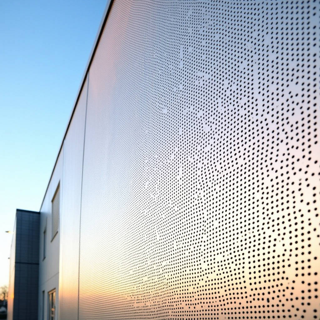
When a facade contractor asks about Aluminum Panel Punching, the question is rarely about the punching itself. What they actually need to know is whether the perforation pattern specified on the architectural drawing can survive a 50-year service life without cracking at the hole edges, corroding from the inside out, or warping under thermal load. The answer depends on three variables that most project specifications overlook: punch-to-edge clearance ratios, post-punch coating integrity on raw cut surfaces, and the structural stiffness loss introduced by open area percentages above 35%. This article addresses each of those variables with field-verified data, because the difference between a perforated facade that performs and one that fails almost always traces back to decisions made before the first punch hits the sheet.
Why Perforated Solid Aluminum Demands Different Engineering Than Flat Sheet
Solid aluminum cladding panels behave predictably when they remain monolithic. A 2.5mm or 3.0mm PVDF-coated sheet spanning between sub-frame members has well-documented deflection characteristics, wind load resistance, and thermal movement behavior. Introduce perforations, and every one of those characteristics shifts. A panel with 30% open area does not retain 70% of its original stiffness. Depending on hole geometry and layout, stiffness loss can reach 50% to 65% of the unperforated value. This is not linear, and it is not intuitive.
The engineering challenge compounds when the perforation pattern is non-uniform. Architects frequently specify gradient patterns where hole density varies across a single panel, creating zones of differential stiffness. A panel that is rigid at the perimeter and flexible in the center develops stress concentrations at the transition boundary. Over thousands of thermal cycles, these boundaries become crack initiation sites. The solution is not to avoid gradient patterns but to calculate the stiffness gradient and match it with sub-frame reinforcement spacing. This requires close coordination between the panel fabricator and the facade engineer during the shop drawing phase, not after panels are in production.
Punch-to-Edge Clearance: The Rule That Most Shop Drawings Miss
Every punch operation displaces material. When a punch tip penetrates 2.5mm solid aluminum sheet, the material around the hole deforms plastically before the slug separates. This deformation zone extends beyond the visible hole diameter. If the deformation zone from one hole overlaps with the deformation zone of an adjacent hole, or with the panel edge, micro-cracking initiates. The industry rule of thumb is minimum edge distance of 2x material thickness, but this is conservative only for static loads. For facade panels subjected to wind-induced cyclic loading, the safe minimum is 3x material thickness from any edge, and 2.5x material thickness between hole centers.
Consider a 3.0mm solid aluminum panel with 8mm diameter perforations. The absolute minimum edge distance should be 9mm, and the minimum center-to-center spacing should be 20mm. When architects push for tighter perforation density, the fabricator must either increase the panel thickness or reduce the panel size to maintain structural integrity. There is no third option. Futeng® has addressed this in numerous projects by providing detailed punch feasibility analyses during the design development phase, identifying patterns that would require impractical thickness increases before the specification is locked.
Calculating Safe Edge Distance for Different Thicknesses
The relationship between material thickness, hole diameter, and safe edge distance is not purely geometric. Aluminum alloy temper also matters. For 3003-H14 and 5052-H32, the two alloys most commonly used in solid aluminum cladding, the elongation before fracture differs significantly. 5052-H32 offers approximately 12% elongation versus 8% for 3003-H14, meaning it tolerates slightly tighter punch spacing before micro-cracking. The table below provides conservative minimums for facade applications with 50-year design life expectations.
| Panel Thickness | Alloy & Temper | Min. Edge Distance | Min. Hole Spacing (Center-to-Center) | Max. Open Area (Single Panel) |
|---|---|---|---|---|
| 2.0mm | 3003-H14 | 6.0mm | 16mm | 25% |
| 2.5mm | 3003-H14 | 7.5mm | 20mm | 30% |
| 3.0mm | 3003-H14 / 5052-H32 | 9.0mm | 24mm | 35% |
| 3.0mm | 5052-H32 | 8.0mm | 22mm | 38% |
| 4.0mm | 5052-H32 | 10.0mm | 28mm | 42% |
These values assume CNC turret punching with proper punch-to-die clearance of 0.15mm to 0.25mm for aluminum. Hydraulic punching with worn tooling can increase the deformation zone by 30% to 40%, requiring proportionally larger edge distances. Always verify tooling condition before running production quantities.
Post-Punch Coating Integrity: The Hidden Corrosion Risk
When a punch penetrates a PVDF-coated aluminum panel, it creates a raw aluminum surface inside the hole. This surface has zero corrosion protection. In a coastal environment with salt spray, or in an industrial zone with acid rain, that bare aluminum begins oxidizing immediately. The corrosion starts inside the hole and propagates under the coating, causing blistering and delamination that can spread centimeters beyond the hole perimeter within three to five years.
The standard solution is to punch first, then coat. But this creates a different problem: coating thickness becomes inconsistent around hole edges. PVDF spray application relies on electrostatic attraction, and hole edges create Faraday cage effects that repel charged paint particles. The result is thinner coating at the very location that needs the most protection. AAMA 2605 specifies minimum 30μm total dry film thickness, but measuring this thickness inside a 6mm hole is practically impossible with standard inspection equipment.
The most reliable approach for Aluminum Panel Punching in corrosive environments is a two-step process: punch the panels, apply a chromate conversion coating to the entire sheet including hole interiors via immersion, then apply PVDF spray coating. The conversion coating provides sacrificial protection inside the holes, while the PVDF handles the face surfaces. This adds approximately 8% to 12% to the per-panel cost but eliminates the most common failure mode in perforated aluminum facades. For projects within 5km of saltwater coastlines, this should be considered mandatory rather than optional.
Coating Sequence Options and Their Trade-offs
| Process Sequence | Corrosion Protection at Hole Edges | Relative Cost | Best Application |
|---|---|---|---|
| Coat first, then punch | None — raw edge exposed | Baseline (100%) | Interior applications, dry climates |
| Punch first, then PVDF spray only | Partial — thin coverage at edges | +5% to 8% | Urban environments, moderate humidity |
| Punch, chromate conversion, then PVDF | Good — sacrificial layer inside holes | +8% to 12% | Coastal, industrial, high-humidity zones |
| Punch, anodize, then PVDF | Excellent — thick oxide layer | +15% to 20% | Severe marine, chemical exposure |
The chromate conversion approach aligns with the pretreatment requirements outlined in AAMA 2605 for high-performance architectural coatings. Specifiers should reference this standard explicitly in the perforated panel section of the specification, not just in the general coatings section, to ensure the fabricator addresses hole-edge protection.
Structural Stiffness Loss: How Open Area Translates to Deflection
A solid aluminum panel spanning 1,200mm between supports, 3.0mm thick, 5052-H32 alloy, deflects approximately 8mm under a 2.0 kPa wind load. Perforate that same panel with 30% open area in a uniform pattern, and deflection increases to roughly 14mm to 18mm, depending on hole layout. The relationship is not linear because the remaining material forms a network of narrow ligaments that bend independently before the panel acts as a unified structure.
The effective moment of inertia for a perforated panel can be approximated by multiplying the solid panel value by (1 - open area ratio)² for uniform hole patterns. For a 30% open area, this gives an effective stiffness of approximately 49% of the original. This means the panel deflects roughly twice as much under the same load. If the original panel was designed to L/180 deflection limit, the perforated version may now exceed L/90, which is unacceptable for most facade specifications.
Three strategies address this stiffness loss. First, reduce the span by adding intermediate sub-frame members. This is the most effective approach but increases the visible framing behind the perforations, which may conflict with the architectural intent. Second, increase panel thickness. Moving from 3.0mm to 4.0mm recovers approximately 70% of the lost stiffness. Third, use a stiffened panel design with formed edges or bonded stiffeners on the rear face. Each approach has cost and aesthetic implications that must be evaluated per project.
Punch Tooling Selection for Production Efficiency
CNC turret punch presses dominate Aluminum Panel Punching for architectural applications because they offer the flexibility to handle multiple hole sizes and shapes without tooling changes. A typical facade project might require 8mm, 12mm, and 20mm diameter holes across different panel types, plus rectangular slots for ventilation openings. A turret with 20 to 40 tool stations can handle this variety in a single setup.
Tooling clearance is the variable that separates clean holes from burred edges. For aluminum, the punch-to-die clearance should be 6% to 8% of material thickness per side. For 3.0mm sheet, this means 0.18mm to 0.24mm clearance. Too tight, and the punch wears rapidly and generates excessive heat that can gall the aluminum. Too loose, and the material tears rather than shears, producing a ragged edge that requires secondary deburring. The ASTM E290 standard provides bend testing protocols that can indirectly validate punch quality by confirming that the material around holes retains sufficient ductility.
Tool coating matters as well. Titanium nitride (TiN) coated punches last 3x to 5x longer than uncoated tool steel when punching aluminum, because aluminum has a tendency to adhere to tool surfaces under pressure. This cold welding effect, called galling, builds up on the punch tip and increases the effective clearance, degrading hole quality over time. TiN coating reduces the coefficient of friction against aluminum and delays galling onset. For production runs exceeding 5,000 hits per punch station, coated tooling is cost-justified.
Thermal Movement in Perforated Panels
Aluminum expands at approximately 0.024mm per meter per degree Celsius. A 3-meter panel subjected to a 60°C temperature swing between winter night and summer sun exposure expands by about 4.3mm. In a solid panel, this expansion is distributed across the entire panel area and accommodated by the fixing system's allowance for movement. In a perforated panel, the expansion concentrates in the remaining material ligaments, which are narrower and therefore experience higher strain per unit of thermal expansion.
For a panel with 30% open area and 6mm-wide ligaments between holes, the effective strain in those ligaments under thermal expansion can be 2x to 3x the nominal strain in a solid panel. Over thousands of cycles, this concentrated strain can initiate fatigue cracking at hole edges, particularly if the holes were punched with dull tooling that left micro-notches. The fix is to specify minimum ligament width based on thermal analysis, not just on structural load analysis. A practical minimum ligament width of 3x material thickness provides sufficient cross-section to distribute thermal strain without exceeding the fatigue limit of 5052-H32 aluminum.
Acoustic Implications of Perforated Facade Panels
Perforated aluminum panels serve a dual purpose on many projects: they provide visual screening while also contributing to acoustic management. When backed by an acoustic absorber such as mineral wool or acoustic membrane, a perforated panel becomes a Helmholtz resonator array. The hole diameter, open area percentage, panel thickness, and cavity depth behind the panel all interact to determine the sound absorption frequency range.
For broad-spectrum sound absorption in the 250Hz to 2,000Hz range relevant to urban traffic noise, hole diameters of 3mm to 6mm with 20% to 25% open area perform well when backed by 50mm to 100mm of mineral wool with a 50mm air gap. The ISO 354 standard governs laboratory measurement of sound absorption, and fabricators should be prepared to provide test data for specific perforation patterns rather than generic values. A pattern with 8mm holes at 30% open area will have a different acoustic signature than 4mm holes at 20% open area, even if both meet the same visual screening requirement.
This acoustic function must be coordinated with the structural requirements. The hole pattern that optimizes sound absorption may not be the same pattern that optimizes structural stiffness. When acoustic performance is a project requirement, the perforation specification should be developed jointly by the acoustic consultant and the facade engineer, with the panel fabricator providing feasibility feedback on both sets of constraints.
Quality Verification: What to Inspect Before Shipment
Perforated aluminum panels cannot be repaired after fabrication. A hole punched in the wrong location, or punched with excessive burring, permanently compromises the panel. This makes pre-shipment inspection more critical for perforated panels than for solid panels. The inspection protocol should cover at least five checkpoints.
First, verify hole diameter tolerance using pin gauges on a statistical sample. For architectural perforations, ±0.1mm on hole diameter is achievable with well-maintained CNC tooling. Second, inspect hole edges under 10x magnification for burrs exceeding 0.1mm. Burrs indicate worn tooling or incorrect clearance and will compromise coating adhesion. Third, check pattern alignment against the approved shop drawing using a coordinate measuring machine or calibrated template. Misalignment of even 1mm becomes visible when panels are installed adjacent to each other. Fourth, verify flatness after punching. The punching process can introduce residual stresses that cause panel bowing, particularly with high open area percentages. Panels should meet the flatness tolerance specified in The Aluminum Association flatness tolerances for sheet product. Fifth, confirm that the coating inside representative holes meets the minimum thickness specification, using destructive testing on sample panels from the production batch.
Cost Drivers in Perforated Aluminum Panel Projects
The cost of perforated aluminum cladding panels is driven by five variables beyond the base material cost. Open area percentage is the primary driver: higher open area means more punch hits, longer machine time, and more material handling. A panel with 40% open area can require 2x to 3x the machine time of a panel with 20% open area, depending on hole size. Smaller holes increase the hit count for a given open area, so 4mm holes at 25% open area cost more to produce than 8mm holes at 25% open area.
Pattern complexity is the second driver. Uniform grid patterns are the most economical because the CNC program is simple and the machine can run at maximum speed. Random or gradient patterns require more complex programming and slower machine speeds to maintain accuracy. The third driver is panel thickness, which affects punch force requirements and tool wear rates. The fourth is coating sequence, as discussed earlier. The fifth is scrap rate: perforated panels cannot be re-cut or re-purposed if errors occur, so the value of lost material is higher than for solid panels.
For budget estimation, perforated panels typically cost 1.5x to 3x the per-square-meter price of equivalent solid panels, with the multiplier depending on the combination of the five drivers above. Projects should budget at the higher end of this range when specifying small holes, high open area, complex patterns, or corrosive-environment coating sequences.
Specifying Aluminum Panel Punching for Long-Term Performance
A specification that treats perforated panels identically to solid panels invites problems. The perforation section should address minimum edge distance, minimum ligament width, post-punch coating requirements, flatness tolerances after punching, and inspection criteria for hole quality. It should reference the relevant ASTM and AAMA standards and require the fabricator to submit punch feasibility analyses with the shop drawings.
The most durable perforated aluminum facades result from early collaboration between the design team, the facade engineer, and the panel fabricator. When the perforation pattern is developed without input from the fabricator, it often requires revision after the bid phase when the fabricator identifies patterns that cannot be produced economically or that would compromise panel longevity. Engaging a fabricator with documented experience in Aluminum Panel Punching during the design development phase, rather than waiting for the tender phase, typically reduces project cost and schedule risk.
Perforated solid aluminum cladding, when engineered correctly, delivers decades of maintenance-free performance. The key is recognizing that a hole is not just an absence of material. It is a feature that changes how the panel behaves structurally, thermally, acoustically, and chemically. Every decision about hole size, spacing, pattern, and processing sequence has consequences that extend far beyond the shop floor. The projects that succeed are the ones where those consequences are understood and addressed before production begins.