Aluminum Panel Press Brake Setup for Solid Cladding From Alloy Choice to CNC Compensation
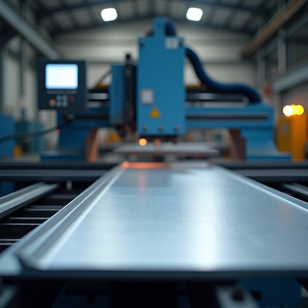
Getting a clean, repeatable bend on solid aluminum cladding panels isn't just about owning a press brake. It's about understanding what happens to 2.0mm, 2.5mm, or 3.0mm PVDF-coated aluminum sheet when the punch meets the grain structure. An Aluminum Panel Press Brake setup that works perfectly for mild steel will destroy a batch of finished aluminum panels in under an hour if the operator hasn't dialed in the right tooling geometry, tonnage curve, and springback compensation. This article focuses on the specific engineering decisions that separate a production-ready bending cell from a costly rework generator. We'll walk through alloy selection logic, die opening calculations, surface protection protocols, and the CNC compensation strategies that high-volume facade fabricators use to hold ±0.5° angular tolerance across thousands of linear feet of cladding.
Why Solid Aluminum Cladding Panels Demand a Different Press Brake Mindset
Solid aluminum sheets in the 2.0mm to 3.0mm range behave nothing like the aluminum composite panels that many shops are accustomed to processing. With ACP, the polyethylene core absorbs some of the deformation stress and the thin aluminum skins bend relatively easily. Solid 3003-H14 or 5052-H32 aluminum at 2.5mm thickness presents a homogeneous cross-section that transmits forming forces directly through the material's grain structure. This means every variable, from die shoulder radius to ram speed, leaves a fingerprint on the finished bend.
The stakes are higher with architectural cladding. A press brake operator bending structural brackets might get away with minor surface marks. On a PVDF-coated facade panel destined for a 40-story curtain wall, those same marks become a rejection criterion. The coating film thickness, typically 25-35 microns for a three-coat PVDF system meeting AAMA 2605, adds another layer of complexity. The coating must stretch with the outer radius without cracking, while the aluminum substrate underneath undergoes plastic deformation. This dual-material behavior means the press brake setup must be validated for both the substrate and the finish system simultaneously.
Temperature matters too. Aluminum's formability changes noticeably between a cold shop floor at 5°C and a summer afternoon at 35°C. The same Aluminum Panel Press Brake settings that produce perfect 90° bends in the morning can yield 88° or 92° results by mid-afternoon if the machine isn't equipped with real-time angle correction and the operator isn't tracking ambient conditions. This isn't theoretical. Shops in the Middle East, where Futeng® has supplied solid aluminum cladding for major projects, routinely deal with 15-20°C temperature swings across a single shift.
Alloy Selection: The Foundation of Predictable Bending
Not all aluminum alloys belong on a press brake. The construction industry predominantly uses two alloy families for solid cladding panels: 3003 and 5052. Each brings a distinct set of bending characteristics that directly influence tooling choices and machine settings.
3003-H14: The Workhorse for Architectural Cladding
3003-H14 is the most common alloy specified for solid aluminum cladding panels. With approximately 1.2% manganese as the primary alloying element, it offers a balanced combination of formability, corrosion resistance, and cost. The H14 temper indicates strain-hardened to half-hard condition, which provides enough strength for facade applications while maintaining a bend radius capability of approximately 1t to 1.5t, meaning a 2.5mm sheet can typically be bent around a 2.5mm to 3.75mm inside radius without cracking.
On a press brake, 3003-H14 exhibits moderate springback, typically 2° to 4° for a 90° air bend depending on die opening and sheet thickness. This is manageable with standard CNC compensation. The material's elongation at break, around 8% to 12% in the H14 temper, provides a reasonable safety margin against edge cracking when the grain direction is properly oriented relative to the bend line.
5052-H32: When Strength Requirements Escalate
5052-H32 contains approximately 2.5% magnesium, pushing tensile strength roughly 30% higher than 3003-H14. This makes it attractive for large-format panels, high-wind-load zones, and applications where panel flatness under thermal cycling is critical. The trade-off is reduced formability. The minimum bend radius for 5052-H32 is typically 1.5t to 2t, and springback increases to 4° to 6° for a 90° air bend.
Press brake operators working with 5052-H32 must pay closer attention to grain direction. Bending perpendicular to the grain (the preferred orientation) yields the most consistent results. Bending parallel to the grain increases the risk of cracking, particularly on the outer radius where tensile stresses concentrate. For architectural panels with complex multi-bend geometries, this may require nesting parts at specific angles on the sheet, potentially reducing material yield but preventing costly scrap.
| Property | 3003-H14 | 5052-H32 | Impact on Press Brake Setup |
|---|---|---|---|
| Tensile Strength (MPa) | 140-180 | 210-260 | Higher tonnage required for 5052 |
| Yield Strength (MPa) | 115 min | 160 min | Greater springback in 5052 |
| Elongation (%) | 8-12 | 7-10 | 3003 more forgiving at tight radii |
| Min. Bend Radius | 1t - 1.5t | 1.5t - 2t | Die selection critical for 5052 |
| Typical Springback (90° air bend) | 2° - 4° | 4° - 6° | CNC compensation range differs |
| Corrosion Resistance | Good | Excellent (marine-grade) | 5052 preferred for coastal projects |
Die Opening Calculations and Tonnage Requirements
The die opening is the single most influential variable in air bending aluminum cladding panels. The industry-standard rule of thumb for mild steel, die opening equals 8 times material thickness, does not translate directly to aluminum. For 3003-H14 and 5052-H32 architectural sheet, a die opening of 6 to 8 times material thickness produces the best balance of bend accuracy, surface quality, and tonnage efficiency.
Here's the practical math. For a 2.5mm thick 3003-H14 panel, a die opening of 16mm (approximately 6.4t) requires roughly 12-14 tons per meter of bend length. The same panel in 5052-H32 might need 16-18 tons per meter. These numbers assume a standard 85° punch and 90° die with appropriate shoulder radii. Narrower die openings reduce tonnage requirements but increase the risk of surface marking and can cause the material to bottom out before the target angle is achieved. Wider openings reduce marking risk but increase springback and the required flange length.
The minimum flange length constraint deserves attention. With a 16mm die opening, the minimum flange that can be formed is approximately 11-12mm, calculated as roughly 70% of the die opening. For architectural panels with short return legs, such as cassette-style cladding with 15mm edge returns, this dictates the maximum usable die opening and, by extension, the press brake tonnage required. Shops that attempt to form short flanges with oversized dies end up with distorted bends and inconsistent angles.
"The relationship between die opening and inside bend radius in air bending is predictable: the inside radius equals approximately 16% of the die opening for aluminum. A 16mm die opening produces roughly a 2.5mm inside radius. This matters because the inside radius directly affects the panel's fatigue performance under wind-induced cyclic loading."
Springback Compensation: The CNC Advantage
Springback is the elastic recovery that occurs after the press brake ram retracts. Aluminum's relatively low elastic modulus (approximately 69 GPa, compared to 210 GPa for steel) means it springs back more than steel for the same bend angle. This isn't a flaw; it's a material property that must be compensated for in the CNC program.
Modern CNC press brakes use several compensation strategies. The most common is angular overbend, where the machine targets an angle deeper than the desired final angle. For 3003-H14 at 2.5mm thickness, a target of 87° to 88° typically yields a 90° final bend when using a 16mm die opening. The exact overbend angle varies with material batch, grain direction, and temperature, which is why real-time angle measurement systems have become standard on production-grade machines.
Laser-based angle sensors mounted on the press brake ram measure the bend angle during the forming stroke and feed correction data back to the CNC controller. This closed-loop system adjusts the ram position on the fly, compensating for variations in material properties within a single sheet or across a production batch. For high-volume facade fabrication, where an Aluminum Panel Press Brake might process 500 to 1,000 panels per shift, this real-time correction eliminates the need for frequent test bends and reduces scrap rates below 0.5%.
Surface Protection: Keeping PVDF Coatings Pristine
The PVDF coating on architectural aluminum cladding represents a significant portion of the material cost. A three-coat system meeting AAMA 2605 specifications involves a primer, a color coat, and a clear topcoat, all oven-cured at precise temperatures. Scratches, die marks, or galling from the press brake tooling can render a panel unusable, and field touch-up is never invisible on a high-rise facade.
Several tooling strategies prevent surface damage. Urethane film dies, where a polyurethane pad is inserted into the bottom die, eliminate metal-to-metal contact on the outer bend surface. The urethane conforms to the bend radius and distributes pressure evenly. The trade-off is reduced bend accuracy compared to hardened steel tooling, typically ±1° versus ±0.5° for precision-ground steel dies.
For applications requiring both accuracy and surface protection, polished and hardened tooling with protective film on the panel is the preferred approach. The tooling is ground to a mirror finish (Ra 0.2 μm or better), and the panel is processed with its factory-applied protective PE film still in place. The film, typically 60-80 microns thick, absorbs minor surface imperfections from the tooling. After bending, the film is removed, revealing an unmarked PVDF surface. This approach works for 90% of architectural bending applications.
For the most demanding jobs, segmented tooling with roller bearings in the die shoulders eliminates sliding friction entirely. The rollers rotate as the material is drawn into the die, preventing the galling that can occur when aluminum slides against steel under high pressure. This technology adds cost but is justified for high-visibility panels on landmark buildings.
Grain Direction and Its Impact on Bend Quality
Aluminum sheet is rolled to its final thickness, and this rolling process elongates the grain structure in the rolling direction. Bending perpendicular to the grain direction (transverse bending) places the grain boundaries under compression, which the material accommodates well. Bending parallel to the grain (longitudinal bending) places the grain boundaries under tension, increasing the risk of cracking on the outer radius.
The practical implication for press brake operations is that panel nesting must account for grain direction. For a rectangular cladding panel with bends on all four sides, the bends parallel to the grain direction may require a larger inside radius than the bends perpendicular to the grain. This might mean using two different die sets for the same panel, or designing the panel geometry so that all bends are oriented favorably relative to the grain.
The ASTM B209 standard for aluminum sheet specifies that mechanical properties are measured in both longitudinal and transverse directions. For 3003-H14, the transverse yield strength is typically 5% to 10% lower than the longitudinal yield strength, which translates to slightly different springback behavior. Shops that process panels without accounting for this anisotropy will see angle variation between bends on the same part.
Press Brake vs. Panel Bender for Solid Aluminum Cladding
The choice between a conventional press brake and a dedicated panel bender has significant implications for cladding fabrication. Press brakes offer flexibility: a single machine can handle a wide range of material thicknesses, bend lengths, and geometries. The tooling investment is lower, and skilled operators are more readily available.
Panel benders, by contrast, automate the entire bending sequence. The sheet is positioned on a manipulator, and a series of bending blades form all four sides in sequence without the operator handling the panel between bends. This eliminates the risk of handling damage on large-format panels and dramatically increases throughput for rectangular parts. A panel bender can process 60 to 100 panels per hour, compared to 15 to 30 for a press brake with manual handling.
The limitation of panel benders for solid aluminum cladding is thickness capacity. Most panel benders are designed for sheet up to 2.0mm or 2.5mm in aluminum. For 3.0mm solid aluminum panels, particularly in 5052-H32, a press brake remains the more capable option. The higher tonnage and larger die openings required for 3.0mm material exceed the design envelope of many panel benders. For shops that process a mix of thicknesses, a hybrid approach, using the panel bender for high-volume 2.0mm work and the press brake for 2.5mm and 3.0mm panels, often delivers the best overall productivity.
CNC Programming Parameters for Consistent Results
Getting the CNC program right eliminates most of the variability in aluminum bending. The key parameters that must be dialed in for each material and thickness combination include ram speed, dwell time, and the pressure curve.
Ram speed affects how the material flows into the die. Aluminum benefits from moderate ram speeds, typically 8 to 12 mm/second for 2.5mm 3003-H14. Slower speeds allow the material to flow more uniformly, reducing the risk of localized thinning. Faster speeds increase throughput but can cause inconsistent bend angles, particularly on longer bends where the ram deflection varies across the length.
Dwell time, the period the ram holds at the bottom of the stroke, has a measurable effect on springback. A dwell of 0.5 to 1.0 seconds allows the aluminum to settle into its plastically deformed state, reducing springback by 0.5° to 1° compared to an immediate retraction. This effect is more pronounced in 5052-H32 than in 3003-H14, likely due to the higher magnesium content and greater work-hardening rate.
The pressure curve, controlled by the CNC's hydraulic or electric servo system, determines how force is applied throughout the stroke. A linear pressure ramp produces acceptable results for most applications. For critical bends, a two-stage curve, where the ram approaches at speed, then slows for the final 2-3mm of travel, provides the most precise angle control. This approach is standard practice for manufacturers like Futeng® when processing aluminum panels for high-specification architectural projects.
Quality Control: Measuring What Matters
Post-bend inspection on solid aluminum cladding panels must address three criteria: angular accuracy, surface condition, and dimensional consistency. Angular accuracy is measured with a digital protractor or, for production environments, a laser scanner that captures the full bend profile. The tolerance for architectural cladding is typically ±1° for standard applications and ±0.5° for premium projects.
Surface condition inspection focuses on the outer bend radius, where tensile stresses are highest. Any cracking, even microscopic, is grounds for rejection. A dye penetrant test can reveal cracks that are invisible to the naked eye. For PVDF-coated panels, the coating on the outer radius should be examined under 10x magnification for micro-crazing that could lead to premature weathering failure.
Dimensional consistency across a production batch reveals whether the press brake setup is stable. Measuring the flange length and bend angle on the first, middle, and last panel of a batch provides a quick check. If the measurements drift, the cause is typically tooling wear, temperature changes, or material batch variation. A well-maintained Aluminum Panel Press Brake with proper CNC compensation should hold flange length within ±0.3mm and angle within ±0.5° across a full shift.
For reference, the AAMA 2605 specification defines the performance requirements for high-performance organic coatings on aluminum extrusions and panels, including post-forming adhesion and flexibility. The ISO 7438 standard specifies the bend test method for metallic materials, providing a standardized procedure for evaluating bend quality. ASTM B209 governs aluminum sheet specifications, including the mechanical properties that directly affect press brake performance.
Tooling Maintenance and Lifecycle Management
Press brake tooling for aluminum cladding requires more frequent inspection and maintenance than tooling used for steel. Aluminum, particularly in its softer tempers, can gall against tool steel, leaving deposits that score subsequent panels. These deposits must be removed regularly using fine-grit polishing compounds or specialized cleaning solutions.
Tooling wear manifests as a gradual increase in the inside bend radius and a corresponding increase in springback. A die that has processed 50,000 linear meters of aluminum will produce measurably different results than a new die, even with identical CNC settings. Shops that track tooling usage and correlate it with bend quality data can schedule die replacement or reconditioning before quality issues arise.
Segmented tooling, where the punch and die are assembled from shorter sections, allows worn sections to be replaced individually rather than replacing the entire tool. This is particularly relevant for shops that process panels of varying lengths, as the wear is concentrated in the sections that are used most frequently. Rotating the segments periodically distributes wear more evenly and extends overall tooling life.
Integrating Press Brake Operations into the Facade Supply Chain
The press brake is one station in a larger fabrication sequence. Upstream, the aluminum sheet is cut to size on a CNC router or waterjet, with the bend allowance already factored into the blank dimensions. The bend allowance for 90° bends in 2.5mm 3003-H14 is approximately 4.0mm to 4.5mm, depending on the die opening. Getting this calculation right at the nesting stage ensures that the finished panel dimensions match the facade engineering drawings.
Downstream, the bent panels move to assembly, where they may be riveted, welded, or mechanically fastened to stiffeners and mounting brackets. The bend quality directly affects assembly fit-up. Panels with inconsistent bend angles create gaps at the corners that must be filled or adjusted, adding labor and compromising the visual quality of the installed facade.
For international projects, where panels may be fabricated in one country and installed in another, the press brake setup must be documented and validated before production begins. First-article inspection reports, including bend angle measurements, surface condition photographs, and dimensional checks, provide the quality assurance that the project's specification requirements will be met consistently across the entire production run.
The Aluminum Association publishes design guidelines that include recommended bend radii for various alloys and tempers. The Construction Specifications Institute provides framework standards for specifying architectural metal fabrication, including the quality control documentation that should accompany fabricated cladding panels. These resources help bridge the gap between press brake operation and facade engineering requirements.
Making the Right Equipment Decision
Selecting an Aluminum Panel Press Brake for solid cladding fabrication involves weighing several factors: tonnage capacity, bed length, CNC capabilities, and the availability of aluminum-specific tooling. A machine that is undersized for the application will struggle with consistency and throughput. A machine that is oversized represents unnecessary capital expenditure.
For a shop processing primarily 2.0mm to 2.5mm 3003-H14 panels up to 4 meters in length, a 150-ton to 200-ton CNC press brake with a 4.2-meter bed provides adequate capacity with some margin. The CNC should include real-time angle measurement and automatic crowning compensation to maintain consistent bend angles across the full bed length. For shops that also process 3.0mm 5052-H32, a 250-ton machine provides the additional tonnage headroom.
The tooling package should include hardened and polished punches and dies with shoulder radii appropriate for the target bend radii. A quick-change tooling system reduces setup time between jobs and makes it practical to switch between different die openings for different panel configurations. The initial investment in quality tooling pays back through reduced scrap, faster setups, and more consistent bend quality.
For fabricators supplying solid aluminum cladding panels to demanding architectural markets, the press brake is not just another machine on the shop floor. It is the point where flat sheet becomes a three-dimensional building envelope component. The precision, consistency, and surface quality achieved at this station ripple through every subsequent step of the facade supply chain, from assembly to installation to decades of in-service performance.