Aluminum Panel CNC Bending Springback Alloy Selection and Machine Choice for Facade Fabrication
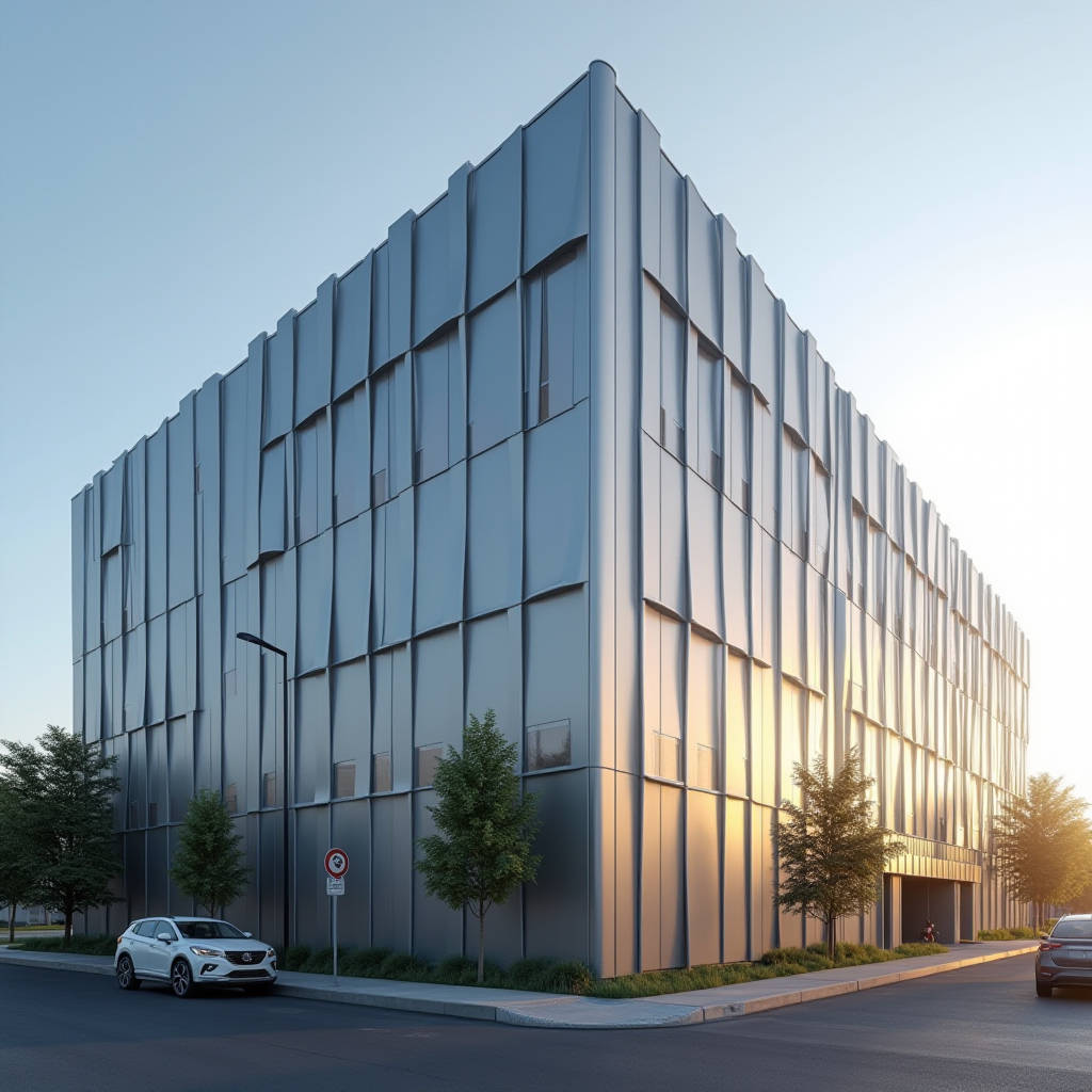
Getting a tight-radius bend on a 3.0mm solid aluminum cladding panel without cracking the grain structure or marking the PVDF surface is not trivial. Architects keep pushing for sharper returns, deeper reveals, and continuous folded geometries that make a facade read as a single monolithic skin. The problem is that aluminum does not always cooperate. Aluminum Panel CNC Bending sits at the intersection of material science, tooling design, and machine calibration. When the process is dialed in correctly, a CNC press brake or automated panel bender can produce hundreds of identical panels with bend angles held to ±0.5° and flange lengths accurate within 0.2 mm. When it is not, you get springback variation, orange-peel texturing on the outside radius, and coating delamination that shows up six months after installation. This article examines the specific technical factors that determine whether a CNC bending operation delivers facade-grade results or a stack of rejected panels.
Why Solid Aluminum Panels Demand a Different Bending Approach
Solid aluminum cladding panels — typically 2.0 mm, 2.5 mm, or 3.0 mm thick sheets of 1xxx, 3xxx, or 5xxx series alloy — behave fundamentally differently on a press brake than steel or aluminum composite material. There is no polyethylene core to absorb stress. The entire cross-section carries the tensile and compressive loads generated during forming. This means every parameter that affects material flow — grain direction, temper, bend radius-to-thickness ratio, and tooling geometry — shows up in the finished part.
The 5xxx series alloys (5052, 5754, 5083) are the most common for architectural cladding because they offer a workable balance of formability, corrosion resistance, and strength. A 5052-H32 sheet at 2.5 mm thickness has a tensile strength around 215–265 MPa and an elongation of 12–18%. That elongation number is critical: it dictates the minimum bend radius before the outer surface begins to micro-crack. The general rule in sheet metal is that the minimum inside bend radius should equal the material thickness for 5052-H32. But on a CNC press brake with properly tuned parameters, fabricators routinely achieve inside radii of 1.5× material thickness without cracking. Pushing below 1.0× thickness on a 3.0 mm panel is where things get risky, and only shops with precise control over punch radius, die opening, and bending speed should attempt it.
Grain direction is another variable that separates facade-grade work from general sheet metal. Aluminum coil is rolled in one direction, and the grain structure aligns with that rolling axis. Bending perpendicular to the grain direction (transverse) reduces the risk of cracking compared to bending parallel (longitudinal). For cladding panels with complex fold patterns — trays, wrap-around column covers, faceted spandrel panels — the nesting layout on the sheet must account for grain orientation on every bend line. A poorly nested panel might have three bends running with the grain and one against it. That one against-grain bend is where cracks initiate. CNC bending software like Radan or SigmaNEST can automate grain-direction-aware nesting, but the operator still needs to flag it.
CNC Press Brake vs. Automated Panel Bender: Choosing the Right Machine
Not all Aluminum Panel CNC Bending is done on the same class of equipment. Two distinct machine types dominate architectural fabrication: the CNC press brake and the fully automated panel bender. Each has a sweet spot, and putting the wrong panel geometry on the wrong machine drives up cost and scrap rate.
A CNC press brake uses a V-die and a punch to form bends one at a time. The operator — or a robotic material handler — positions the sheet, the ram descends, and the bend is formed by forcing the material into the die. Modern CNC press brakes from manufacturers like Amada, Trumpf, and HARSLE offer closed-loop hydraulic or servo-electric control with crowning systems that compensate for frame deflection across the bed length. For architectural panels, the key advantage of a press brake is flexibility: it handles deep box bends, hemmed edges, and variable-radius work that a panel bender cannot. The downside is that each bend requires a handling cycle, and on a 3-meter-long panel with four bends, that means four positioning operations. Each positioning introduces the possibility of misalignment or surface scratching.
An automated panel bender — Salvagnini and HARSLE are two prominent names — flips the logic. The sheet is clamped flat on a vacuum table, and a swinging blade executes bends from below while the sheet remains stationary. This eliminates the need to reposition the workpiece between bends, which dramatically reduces cycle time and eliminates handling-related defects. The bending blade can also rotate to form flanges in multiple directions without flipping the sheet. For high-volume production of standard cladding panels — cassette panels, flat trays, simple return-flange panels — a panel bender can run circles around a press brake. Cycle times of 15–30 seconds per panel are achievable versus 2–4 minutes on a press brake for the same geometry.
The trade-off is geometric flexibility. Panel benders struggle with deep return flanges that exceed the blade height, and they cannot form radius bends or hems. If the project involves curved facade elements or panels with complex folded edge details, a press brake is the only option. Many shops serving the architectural market run both machines side by side and route panels accordingly.
| Parameter | CNC Press Brake | Automated Panel Bender |
|---|---|---|
| Typical bend angle accuracy | ±0.5° with angle compensation | ±0.3° with servo control |
| Flange length repeatability | ±0.15 mm | ±0.10 mm |
| Cycle time per panel (4 bends, 2.5 m) | 2–4 minutes | 15–30 seconds |
| Max panel thickness (5052 alloy) | Up to 6.0 mm (tonnage-dependent) | Typically 3.0 mm max |
| Radius bends / hems | Yes, with appropriate tooling | No |
| Deep return flanges (>150 mm) | Yes | Limited by blade height |
| Surface scratch risk | Moderate (handling-dependent) | Low (sheet stays on table) |
| Operator skill requirement | High | Moderate |
| Ideal application | Complex geometries, radius work, deep boxes | High-volume flat trays, cassette panels |
Springback Compensation: The Math That Makes or Breaks Facade Tolerances
Aluminum has a modulus of elasticity roughly one-third that of steel — about 69 GPa for most architectural alloys versus 200 GPa for carbon steel. This means aluminum springs back significantly more after bending. A 90° bend in 5052-H32 might spring back to 86° or 87° if the machine does not compensate. On a 3-meter-long cladding panel, a 3° angular error translates to a 5 mm gap at the panel edge. That gap is visible from the street, and it is a water ingress path.
Springback is not a constant. It varies with material thickness, bend radius, die opening width, and even the batch of coil. CNC press brakes address this through adaptive angle measurement. A laser or mechanical probe measures the bend angle after the ram retracts, and the control system adjusts the punch depth on the next stroke. On a modern CNC press brake with real-time angle feedback, the machine can hit target angles within ±0.3° on the first part and hold that tolerance across the entire production run.
The die opening width (V-width) is a lever that engineers use to control springback. A narrower V-die opening concentrates the bending force and reduces springback, but it also increases the risk of cracking on the outside radius. The standard rule for aluminum is a V-opening of 8× material thickness. For 2.5 mm 5052, that means a 20 mm V-die. Going down to 6× thickness (15 mm V-die) will reduce springback but demands careful attention to punch radius and surface condition. Some shops use a 6× V for 3xxx series alloys and an 8× V for 5xxx series as a starting point, then adjust based on trial bends.
Temperature matters too. Aluminum's yield strength drops slightly as temperature increases. A shop floor that is 10°C in winter and 35°C in summer will see measurable differences in springback behavior on the same alloy and thickness. This is not usually a problem for architectural panels with standard tolerances of ±1.0 mm, but on projects specifying ±0.5 mm flatness across a folded panel, temperature-compensated bending parameters become necessary.
Tooling Selection and Surface Protection for Coated Panels
The vast majority of architectural aluminum cladding panels arrive at the bending stage with a PVDF or powder coating already applied. This is partly practical — bending a coated flat sheet is faster than post-coating a formed panel — and partly quality-driven, because the coating encapsulates the folded edges and protects them from corrosion. But bending a coated panel introduces a specific risk: tooling marks, scratches, and coating cracking on the outside radius.
The punch and die that contact the panel must be absolutely clean and free of burrs. Even a tiny metallic particle embedded in the die shoulder can scribe a line across the PVDF surface as the material slides. Shops that specialize in architectural work use urethane film protectors on the die shoulders, or they specify polished and hardened tooling with a surface finish of Ra 0.2 µm or better. Some go further and use die inserts made from non-marring materials like acetyl or specialized polymers.
The protective film on the panel itself is the first line of defense. PVDF-coated panels from reputable suppliers ship with a peelable polyethylene or polyester film, typically 50–70 microns thick. The film must remain intact through the bending operation. If the film tears or lifts at the bend line, the coating underneath is exposed to tooling contact. The film's adhesion and elongation must be specified to survive the bending strain. A film that stretches 200% without tearing is adequate for most architectural bends. A film that stretches only 50% will fail on a sharp radius.
Coating flexibility is the other half of the equation. PVDF coatings based on 70% Kynar 500® or Hylar 5000® resin systems are formulated to withstand bending without cracking, but only within limits. The standard AAMA 2605 specification requires that PVDF coatings pass a 2T bend test — meaning the coated panel is bent 180° around a mandrel with a diameter equal to twice the panel thickness, and the coating must not crack. For a 2.5 mm panel, that is a 5 mm mandrel diameter. Most architectural bends are far less severe than a 2T bend, so coating cracking is rarely a problem if the bend radius stays above 1.5× material thickness. But when architects specify sharp 90° corners with minimal radius, the coating can micro-crack on the outside surface. Those cracks are invisible to the naked eye immediately after bending, but they open up over thermal cycles and become corrosion initiation points.
Quality Control and Tolerance Stack-Up in Facade Fabrication
Facade panels do not exist in isolation. A single panel that is 1 mm out of square might be acceptable on its own, but when 200 panels are installed side by side on a unitized curtain wall, the cumulative error can push the joint alignment beyond the specified ±2 mm. Aluminum Panel CNC Bending must be understood as part of a larger tolerance chain that includes the supporting subframe, the anchor system, and the building structure itself.
The first QC checkpoint is dimensional verification of the flat blank before bending. A laser-cut or turret-punched blank that is 0.5 mm oversize in length will produce a panel that is 0.5 mm oversize after bending, regardless of how accurately the bends are placed. Shops that run both cutting and bending under CNC control can close the loop by feeding blank measurement data back to the bending program, adjusting the bend line positions to compensate for blank variation.
After bending, the critical dimensions are flange height, overall panel dimensions, diagonal measurements (squareness), and bend angle. Flange heights are measured with a height gauge or a coordinate measuring machine (CMM) for critical panels. A ±0.3 mm tolerance on flange height is achievable with a well-maintained CNC press brake. Diagonal measurements should be within ±1.0 mm for panels up to 2 meters, and ±1.5 mm for larger panels. These numbers align with the tolerances specified in AAMA 609 & 610 for architectural aluminum, which calls for a maximum variation of 1.5 mm per 1.8 meters of panel dimension.
Surface inspection under controlled lighting is essential for coated panels. A panel that looks perfect under warehouse fluorescent lights might show waviness or oil-canning when installed on a south-facing facade with direct sunlight. The industry term for this is "optical flatness," and it is assessed by viewing the panel at a shallow angle under a grid of reflected light. CNC bending contributes to optical flatness through the consistency of the bend line: a bend that varies in angle by 0.2° along its length will introduce a subtle twist that catches the light differently than the adjacent panel.
Alloy Selection and Temper: Matching the Material to the Bend Geometry
Not all aluminum alloys bend the same way. The choice of alloy and temper has a direct impact on minimum bend radius, springback, and the risk of cracking. For architectural cladding, three alloy families dominate:
1xxx series (1050, 1060, 1100): Commercially pure aluminum with 99.0%+ aluminum content. Extremely soft and formable. Minimum bend radius can go as low as 0.5× material thickness. The downside is low strength — tensile strength around 75–110 MPa in the H14 temper — which means panels must be thicker to achieve the same stiffness as a 5xxx alloy panel. Rarely used for exterior cladding in thicknesses below 3.0 mm because of dent resistance concerns.
3xxx series (3003, 3004, 3105): Aluminum-manganese alloys with moderate strength (110–180 MPa tensile) and excellent formability. 3003-H14 is a workhorse for architectural sheet metal, with a minimum bend radius of 1.0× thickness in most conditions. It welds well and takes PVDF coating with standard pretreatment. The 3105 alloy is specifically designed for architectural applications like siding and soffit panels.
5xxx series (5052, 5754, 5083): Aluminum-magnesium alloys with higher strength (190–290 MPa tensile) and good corrosion resistance. 5052-H32 is the most common choice for solid aluminum cladding panels because it balances formability with the stiffness required for large-format panels. Minimum bend radius is typically 1.5× thickness. 5083-H116 is used for marine and coastal environments where higher corrosion resistance is needed, but it is harder to bend and requires larger radii.
The temper designation matters as much as the alloy. H32 (strain-hardened and stabilized to 1/4 hard) is the standard for architectural 5052. H34 (1/2 hard) offers higher strength but reduced formability. H111 (annealed and slightly strain-hardened) bends beautifully but may not meet the flatness requirements for large panels. The fabricator must verify that the mill test certificate (MTC) from the aluminum supplier confirms the specified temper and that the mechanical properties fall within the expected range for the bending parameters being used.
Futeng® supplies solid aluminum cladding panels in 5052-H32 and 3003-H14 as standard, with full MTC documentation traceable to the coil. For projects requiring non-standard alloys or tempers, the mill lead time and minimum order quantity must be factored into the project schedule early.
Programming and Simulation: Reducing Trial-and-Error on the Shop Floor
The days of programming a press brake by typing in bend angles and hoping the first part comes out right are fading. Offline programming and bending simulation software — Radan, SigmaNEST, Lantek, and Dr. ABE Bend — allow the bending sequence, tooling setup, and springback compensation to be simulated before any metal is cut. This is particularly valuable for Aluminum Panel CNC Bending because the cost of scrapping a 3.0 mm PVDF-coated panel is significant: the material alone can be $80–120 per square meter, plus the lost coating cost and production time.
A proper simulation workflow starts with importing the 3D CAD model of the panel. The software extracts the bend lines, identifies the bend angles and flange dimensions, and checks for collisions between the panel and the tooling or machine frame during the bending sequence. This collision check is critical for panels with multiple bends in different directions — a panel that folds back on itself can collide with the press brake frame if the bend sequence is not carefully planned.
The software then calculates the required bend allowance and develops the flat blank dimensions. Bend allowance — the length of the neutral axis through the bend — depends on the material, thickness, bend radius, and bend angle. The standard formula is: BA = (π/180) × (R + K × T) × A, where R is the inside bend radius, T is the material thickness, A is the bend angle, and K is the K-factor (the ratio of the neutral axis position to the material thickness). For 5052-H32 aluminum, the K-factor typically falls between 0.33 and 0.38 for air bending with a V-die. Getting the K-factor wrong by 0.05 can shift the flat blank dimension by 0.5 mm per bend, which adds up to a 2 mm error on a panel with four bends.
Once the flat blank is calculated, the software generates the CNC code for the press brake, including the back-gauge positions for each bend, the punch stroke depth, and the dwell time. The code is transferred to the machine controller, and the first article is bent. If the simulation was accurate, the first article should be within tolerance. If not, the operator adjusts the angle correction and re-bends. The goal is to get to a good first article in one or two iterations, not five or six.
For automated panel benders, the programming is simpler because the machine handles the material positioning. The operator loads the blank, the vacuum table clamps it, and the bending blade executes the programmed sequence. The main programming task is defining the bend sequence and the blade angle for each bend. Some panel benders can automatically adjust the blade angle based on material thickness and bend angle, but the operator still needs to verify that the programmed parameters are correct for the specific alloy and temper.
Common Defects and Their Root Causes
Understanding what goes wrong — and why — is how fabricators move from acceptable quality to consistently excellent output. The following defects are the most frequently encountered in architectural aluminum panel bending:
Corner cracking: Cracks that initiate at the intersection of two bend lines, typically on the outside radius. Root cause is almost always excessive strain at the corner. The material at a corner where two bends meet is stretched in two directions simultaneously, and the combined strain can exceed the material's formability limit. The fix is to increase the bend radius, use a softer temper, or add a relief notch at the corner before bending. Relief notches are common on tray panels where the corner is welded and ground after bending.
Springback variation: Panels that come out at different angles even though the machine parameters are identical. Root cause is usually material property variation from coil to coil or even within a single coil. The yield strength of 5052-H32 can vary by ±15 MPa within the specification. A 15 MPa difference in yield strength changes the springback by 0.5°–1.0°. The fix is to use adaptive angle measurement on every bend, or to segregate coils by mill test certificate and adjust bending parameters for each coil batch.
Surface marking: Scratches, scuffs, or indentations on the coated surface. Root cause is tooling condition, die shoulder roughness, or debris between the panel and the tooling. The fix is regular tooling inspection and cleaning, use of protective film, and die shoulder polishing. Some shops dedicate a set of tooling exclusively to coated aluminum panels and never use it for steel or stainless steel.
Twist or warp: The panel does not lie flat on a surface plate after bending. Root cause is uneven stress distribution along the bend line, often caused by a worn die that has a different radius at the center than at the ends. The fix is die maintenance and crowning adjustment on the press brake. On a panel bender, twist can be caused by uneven clamping pressure on the vacuum table.
Inconsistent flange height: The flange height varies along the length of the bend. Root cause is back-gauge positioning error or blank dimensional variation. The fix is to verify back-gauge calibration and to measure blank dimensions before bending.
Integrating CNC Bending into the Facade Supply Chain
For the general contractor or facade subcontractor, the bending operation is one link in a chain that starts with design intent and ends with an installed, watertight facade. The specification for Aluminum Panel CNC Bending should be written into the facade package in a way that is measurable and enforceable.
The specification should reference the applicable standards: AAMA 609 & 610 for dimensional tolerances, ASTM B209 for aluminum sheet and plate, and ISO 2768 for general tolerances if the project is outside North America. The bend radius, angle tolerance, and surface quality requirements should be stated explicitly, not left to the fabricator's discretion.
Shop drawings should show the unfolded flat pattern with bend lines, grain direction, and critical dimensions. The bend sequence should be noted if it affects the final geometry. For panels with welded corners, the welding procedure and post-weld grinding and coating touch-up should be specified.
First-article inspection is non-negotiable. The fabricator should produce one complete panel from production tooling and material, and that panel should be inspected against all dimensional and surface quality requirements before the production run begins. The approved first article becomes the reference standard for the remainder of the project.
Batch inspection during production should sample panels at a defined frequency — one panel per 50 or per shift, depending on the project's quality plan. The inspection should cover the same dimensions as the first article, and the results should be documented and traceable to the production batch.
For the procurement manager, the key commercial considerations are the cost of bending versus the cost of material. A panel that requires 12 bends will cost more to fabricate than a simple flat panel with four return flanges. The bending cost is driven by machine time, which is driven by the number of bends and the complexity of the handling. A panel bender can process 4-bend panels at a rate of 120–180 per hour, while a press brake might manage 15–30 per hour for the same panel. The hourly rate for a panel bender is higher than a press brake, but the per-panel cost is lower for high-volume, simple geometries. The break-even point depends on the specific panel design and the shop's equipment mix.
Lead times for bending are typically 2–4 weeks from approved shop drawings, but this can stretch to 6–8 weeks for complex projects with custom tooling requirements. The bending schedule must be coordinated with the coating schedule, because coated panels should not sit in storage for months before bending — the protective film can bond to the coating over time, making it difficult to remove.
The facade industry continues to push the limits of what can be achieved with folded aluminum. Tighter radii, larger panels, thinner gauges, and more complex geometries are all trends that put pressure on the bending process. The shops that invest in modern CNC equipment, train their operators on material-specific parameters, and implement rigorous quality control are the ones that deliver panels that look right, fit right, and last.