How Thermal Movement Shapes Precision in Aluminum Facade Fabrication
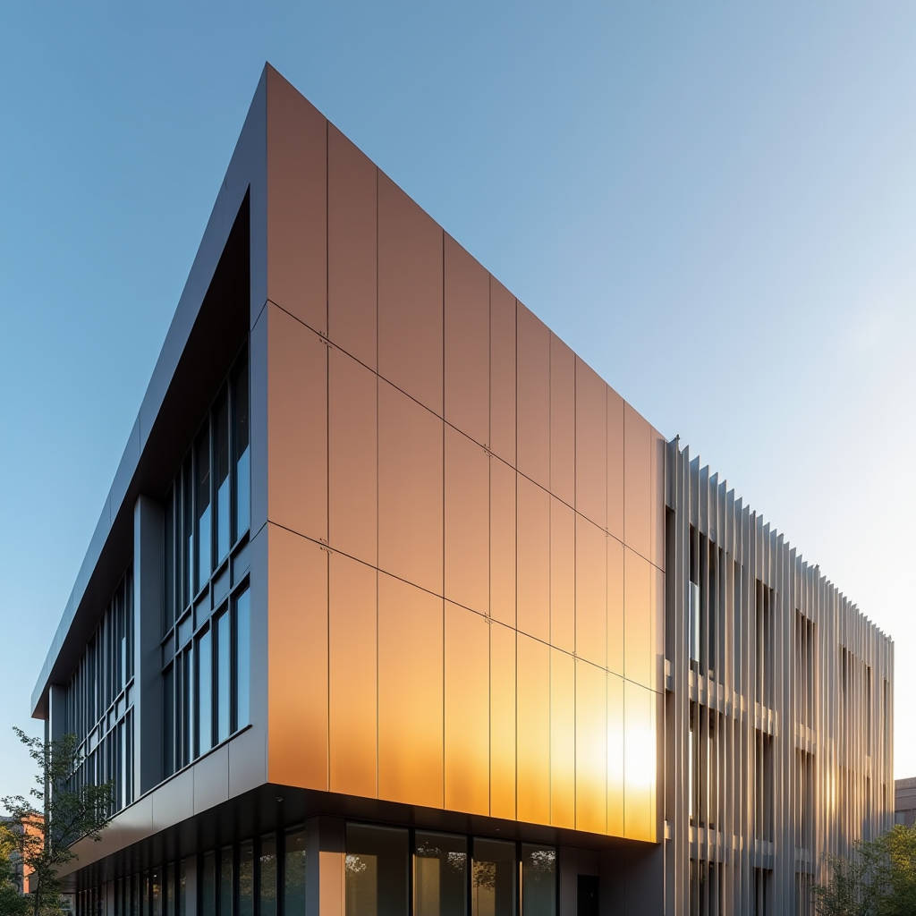
Aluminum Facade Fabrication sits at the intersection of precision engineering and architectural ambition. Every solid aluminum panel that leaves a fabrication facility carries a set of decisions made weeks or months earlier — about alloy grade, temper, coating chemistry, and dimensional tolerances. Getting those decisions right means the difference between a facade that performs for 30 years and one that starts showing distress in five. This article focuses on a dimension of fabrication that rarely gets the attention it deserves: thermal movement accommodation in solid aluminum cladding systems. When panels span 3 meters or more, the linear expansion of aluminum becomes a structural reality that no amount of clever detailing can ignore. For architects specifying large-format panels and facade contractors responsible for installation, understanding how fabrication tolerances interact with thermal dynamics is not optional. It is the foundation of a weathertight, wrinkle-free building skin.
Why Thermal Movement Defines Aluminum Facade Performance
Aluminum expands at roughly 2.4 mm per linear meter for every 100°C temperature change. On a 4-meter panel subjected to a 60°C surface temperature swing between a winter night and summer midday, that translates to nearly 5.8 mm of movement. Multiply that across a facade with hundreds of panels, and the cumulative displacement can exceed 50 mm across a building elevation. Fabrication shops that do not account for this in panel sizing, joint design, and attachment engineering are essentially building latent failure into the system.
The coefficient of thermal expansion for 5000-series and 3000-series aluminum alloys — the two most common families in solid aluminum cladding — hovers around 23.8 × 10⁻⁶ /°C. This is roughly twice that of steel and three times that of concrete. When a solid aluminum panel is mechanically fixed to a steel subframe embedded in a concrete slab, three materials with three different expansion rates are forced into a relationship. The fabrication strategy must resolve this mismatch, not ignore it.
What makes this particularly challenging in Aluminum Facade Fabrication is that the very properties that make aluminum desirable — its light weight, its ability to be formed into complex geometries, its corrosion resistance — also make it thermally active. A 2.5 mm thick solid panel does not have the thermal mass to resist rapid temperature changes. It heats up fast, cools down fast, and moves with every cycle. Over a 30-year service life in a temperate climate, a facade panel might experience 15,000 to 20,000 thermal cycles. Each cycle is a micro-test of the fabrication quality.
Alloy Selection and Its Impact on Fabrication Strategy
Not all aluminum alloys behave identically under thermal load. The choice of alloy directly influences how a fabrication shop approaches panel sizing, ribbing, and attachment detailing. Three alloys dominate the solid aluminum cladding market:
AA 5005 (Al-Mg system): The workhorse of architectural cladding. With magnesium content around 0.8-1.1%, it offers a balance of formability, corrosion resistance, and anodizing response. Its thermal expansion coefficient is 23.8 × 10⁻⁶ /°C. Yield strength in the H14 temper runs approximately 150 MPa. This alloy bends well, welds cleanly, and accepts PVDF coatings with excellent adhesion. Most fabrication shops in Asia and Europe default to 5005 for standard rainscreen panels.
AA 3003 (Al-Mn system): Slightly softer than 5005, with yield strength around 125 MPa in H14 temper. Its thermal expansion is marginally higher at 24.0 × 10⁻⁶ /°C. The advantage is superior formability for panels requiring deep draws or complex perforation patterns. The trade-off: panels may require additional stiffening ribs to maintain flatness under thermal cycling.
AA 5754 (Al-Mg system): Higher magnesium content (2.6-3.6%) gives this alloy yield strength approaching 190 MPa in H22 temper. Thermal expansion is 23.9 × 10⁻⁶ /°C. This is the choice for large-format panels exceeding 3 meters in any dimension, where wind load deflection limits demand higher stiffness. The higher strength allows fabrication shops to use thinner material — 2.0 mm 5754 can often replace 2.5 mm 5005 — but the material cost is 15-20% higher.
The fabrication implications cascade from this alloy choice. A shop running 5754 panels needs different tooling clearances, different bend radii, and different welding parameters than one running 3003. The thermal expansion differences, while small in absolute terms, accumulate over large panel dimensions. A 4-meter 3003 panel will move approximately 0.8 mm more than a 4-meter 5005 panel under the same temperature swing. That 0.8 mm must be absorbed somewhere in the joint system.
Fabrication Tolerances That Matter for Thermal Movement
The standard fabrication tolerance for solid aluminum panels is often quoted as ±1.5 mm on length and width, and ±0.5 mm on thickness. But these numbers, drawn from general sheet metal practice, do not address the tolerances that actually matter for thermal performance: joint gap consistency, fastener slot precision, and flatness under thermal load.
A panel-to-panel joint designed for 10 mm nominal gap will function differently if fabrication tolerances produce actual gaps ranging from 8 mm to 12 mm. At 8 mm, a 5.8 mm thermal movement consumes 73% of the available gap. At 12 mm, the same movement consumes only 48%. The joint sealant — typically a high-performance silicone with ±25% movement capability — has a defined working range. Fabrication shops that hold joint-critical dimensions to ±0.5 mm rather than ±1.5 mm give the installation team a fighting chance at long-term weathertightness.
Fastener slot tolerances are equally critical. Most solid aluminum panel systems use slotted connections at the fixed point to allow directional movement. A slot specified at 12 mm ± 0.5 mm provides a known movement envelope. A slot that comes off the CNC router at 11 mm or 13 mm changes the entire thermal accommodation strategy. The best fabrication shops — including facilities like Futeng® that specialize in architectural aluminum — use CNC machining centers with positioning accuracy of ±0.1 mm for all attachment features. This level of precision is not about aesthetics; it is about ensuring that the engineered movement joints actually work as calculated.
Coating Systems and Thermal Behavior
The coating on a solid aluminum panel does more than provide color. It influences the panel's surface temperature, which directly affects thermal movement. Dark-colored panels absorb more solar radiation and run hotter than light-colored panels on the same building, on the same day. A black PVDF-coated panel can reach 80°C on a 35°C summer afternoon, while a white panel on the same facade might stay at 45°C. The 35°C surface temperature difference produces additional thermal movement of roughly 0.84 mm per meter of panel length.
This means fabrication shops and specifiers must consider color as a thermal variable, not just an aesthetic one. The three dominant coating systems each have different solar absorptance characteristics:
| Coating System | Typical DFT (μm) | Solar Reflectance (Light Colors) | Solar Reflectance (Dark Colors) | Max Service Temp | Thermal Movement Factor |
|---|---|---|---|---|---|
| PVDF (70% Kynar 500®) | 25-35 | 0.70-0.85 | 0.05-0.30 | 120°C | 1.0 (baseline) |
| FEVE (Fluoroethylene Vinyl Ether) | 25-40 | 0.65-0.80 | 0.05-0.28 | 100°C | 1.0-1.05 |
| Polyester (Super Durable) | 20-30 | 0.60-0.75 | 0.04-0.25 | 90°C | 0.95-1.0 |
| Anodized (Class I, AA-M12C22A31) | 15-25 | 0.50-0.70 | 0.03-0.20 | 150°C | 1.0 |
The thermal movement factor is a practical multiplier that fabrication engineers can apply to baseline expansion calculations. A dark FEVE-coated panel in a hot climate may need 5% more joint width than a dark PVDF panel, simply because the FEVE coating absorbs marginally more solar energy. These are small numbers that compound across thousands of panels.
PVDF coatings based on 70% Kynar 500® resin remain the industry standard for architectural aluminum, governed by AAMA 2605. The specification requires a minimum total dry film thickness of 25 μm for a two-coat system and 30 μm for a three-coat system. The coating must withstand 4,000 hours of accelerated weathering with color change (ΔE) not exceeding 5.0 units. For projects in coastal or high-UV environments, the three-coat system with a clear topcoat provides measurable additional protection against chalking and fading.
Substructure Compatibility and Thermal Isolation
The aluminum panel does not exist in isolation. It attaches to a subframe — typically aluminum extrusions, galvanized steel, or stainless steel — which in turn connects to the building structure. The thermal expansion mismatch between these materials creates shear forces at every connection point. A solid aluminum panel expanding at 23.8 × 10⁻⁶ /°C against a galvanized steel subframe expanding at 12.0 × 10⁻⁶ /°C generates a differential movement of roughly 11.8 × 10⁻⁶ /°C. Over a 3-meter panel length and a 60°C temperature swing, that is approximately 2.1 mm of differential movement at each connection.
Fabrication shops address this through three primary strategies:
Slotted connections: The most common approach. The panel's attachment clips feature elongated holes that allow the panel to slide relative to the subframe. The slot length is calculated based on the expected differential movement plus a safety factor of 1.5. For a 2.1 mm calculated movement, the slot provides at least 3.2 mm of travel in each direction. CNC-punched slots are preferred over manually drilled ones because the slot edges are cleaner and the dimensions are more consistent.
Thermal breaks: For projects where energy codes require continuous insulation, thermal break pads made from polyamide or PVC are inserted between the panel clip and the subframe. These pads reduce thermal bridging but also introduce a degree of compliance into the connection. The pad material must have sufficient compressive strength (typically >50 MPa) to prevent creep under dead load while allowing micro-movement.
Floating subframes: For large-format panels (over 3.5 meters in any dimension), a floating subframe system decouples the panel from the primary structure. The panel is rigidly fixed to an intermediate aluminum frame, which is then connected to the building with slotted attachments. This approach isolates panel-level thermal movement from building-level structural movement, which is particularly important in seismic zones.
The AAMA 501.4 standard provides a test method for evaluating the thermal movement capability of curtain wall and cladding systems. While originally developed for curtain wall, the principles apply directly to rainscreen cladding. A system that passes AAMA 501.4 has demonstrated the ability to accommodate thermal movement without distress to seals, fasteners, or panel finishes.
Panel Geometry and the Flatness Challenge
Thermal movement does not just affect joints. It affects panel flatness. A solid aluminum panel that is perfectly flat at 20°C in the fabrication shop may develop oil-canning — a visible waviness or buckling — when it heats up to 70°C on a summer facade. The mechanism is straightforward: the panel expands, but the perimeter attachments constrain it, creating compressive stresses that buckle the panel out of plane.
Fabrication shops combat thermal buckling through stiffening strategies. The most common is the application of aluminum stiffener ribs bonded to the panel back with structural adhesive. The rib spacing is calculated to keep the panel's width-to-thickness ratio within limits that prevent buckling under the expected thermal compressive stress. For a 2.5 mm thick 5005-H14 panel, a rib spacing of 400-500 mm typically maintains flatness for panels up to 1.5 meters wide. Wider panels require closer rib spacing or thicker material.
The stiffener attachment method matters. Mechanical fasteners (rivets or screws) create point connections that can telegraph through to the panel face under thermal cycling, producing visible dimpling. Structural adhesive bonding — using two-part epoxy or polyurethane adhesives — distributes the connection stress over a larger area and eliminates face dimpling. The adhesive must maintain bond strength across the full temperature range the panel will experience, typically -40°C to +80°C. ASTM C881 provides performance specifications for epoxy adhesives used in structural bonding applications.
Perforated panels present a special case. The perforations reduce the panel's effective stiffness, making it more susceptible to thermal buckling. Fabrication shops must either increase the material thickness, decrease the rib spacing, or both. A panel with 30% open area (typical for solar shading applications) may require material 0.5 mm thicker than a solid panel of the same dimensions to achieve equivalent flatness under thermal load.
Quality Control Protocols for Thermal-Critical Fabrication
Fabrication quality control for thermally active cladding systems must go beyond dimensional checks. The following QC protocols separate high-performance fabrication from commodity sheet metal work:
Incoming material verification: Every coil of aluminum entering the fabrication shop should be accompanied by mill test certificates that verify alloy composition, temper, and mechanical properties. A shop that does not verify incoming material is gambling. A coil of 3003-H14 mistakenly run as 5005-H14 will produce panels with different thermal expansion characteristics and lower strength. The difference may not be visible at installation but will manifest over years of thermal cycling.
Slot dimension verification: Every production batch should include a statistical sample of slotted connections measured with a calibrated go/no-go gauge. The gauge confirms that the slot length and width fall within the specified tolerance band. A slot that is too short restricts thermal movement. A slot that is too wide introduces slop that can lead to panel rattling under wind load.
Adhesive bond testing: For stiffener-to-panel adhesive bonds, destructive testing of sample coupons from each production batch provides confidence that the bond will survive thermal cycling. A pull-off test per ASTM D4541 should show cohesive failure within the adhesive, not adhesive failure at the bond line. Cohesive failure indicates that the adhesive is stronger than the bond to the substrate — the desired failure mode.
Thermal cycling simulation: For critical projects, a full-scale mockup of a representative facade section should undergo thermal cycling in a controlled environment. The mockup cycles between -20°C and +80°C for a minimum of 50 cycles while engineers monitor joint movement, sealant adhesion, and panel flatness. This test, while expensive, reveals problems that calculations alone cannot predict.
The Centre for Window and Cladding Technology (CWCT) in the UK provides detailed guidance on thermal cycling test protocols for rainscreen cladding systems. Their Sequence B testing includes thermal cycling as a standard component of system performance verification.
Practical Engineering Data for Specification
For facade engineers and specifiers, the following data points provide a practical starting point for thermal movement calculations in solid aluminum cladding systems:
- Linear thermal expansion coefficient: 23.8 × 10⁻⁶ /°C (5005, 5754); 24.0 × 10⁻⁶ /°C (3003)
- Design temperature range (temperate climate): -20°C to +70°C (90°C span)
- Design temperature range (desert climate): -10°C to +85°C (95°C span)
- Design temperature range (coastal tropical): +5°C to +65°C (60°C span)
- Minimum joint width for 3m panel (temperate): 10 mm (sealant), 15 mm (open joint)
- Minimum joint width for 4m panel (temperate): 14 mm (sealant), 20 mm (open joint)
- Minimum joint width for 4m panel (desert): 16 mm (sealant), 22 mm (open joint)
- Recommended slot length safety factor: 1.5 × calculated movement
- Stiffener spacing for 2.5mm panel (5005-H14): 400-500 mm centers
- Stiffener spacing for 3.0mm panel (5005-H14): 500-600 mm centers
These numbers assume mechanically restrained connections at panel corners with intermediate connections providing directional release. Fixed-point locations should be specified at the panel center or at one corner, depending on the overall facade geometry and the location of building movement joints. The fixed point is the reference from which all thermal movement radiates. Placing it incorrectly can double the effective panel length for thermal movement calculations.
Installation Sequencing and Thermal Considerations
Even perfectly fabricated panels can perform poorly if installed without regard for thermal conditions. A panel installed tight on a cold winter morning will be in compression by summer afternoon. A panel installed with generous gaps on a hot day may show excessive joint width in winter. The fabrication shop cannot control installation conditions, but it can provide clear guidance on the temperature at which joint dimensions were calibrated.
Best practice is to fabricate panels with joint dimensions calibrated to a reference temperature of 20°C. The installation team should be aware that joints will appear wider at lower temperatures and narrower at higher temperatures. If the installation temperature deviates significantly from 20°C, the joint width should be adjusted accordingly. A 10°C deviation changes the joint width by approximately 0.24 mm per meter of panel length — a small number that matters for tight-tolerance systems.
For projects where panels are fabricated months before installation, storage conditions matter. Panels stored in direct sunlight can reach surface temperatures of 60°C or higher. If they are installed immediately after being brought into an air-conditioned interior at 22°C, the thermal shock can cause temporary distortion. Allowing panels to acclimate to installation temperature for 24 hours before fixing is a simple precaution that avoids unnecessary callbacks.
When Fabrication Precision Meets Site Reality
The gap between fabrication shop precision and site reality is where many facade problems originate. A panel fabricated to ±0.5 mm tolerance on a CNC machine gets installed on a concrete slab that may be ±15 mm from design position. The subframe installer compensates with shims and slotted brackets, but the accumulated tolerance stack can consume the thermal movement allowance before the panel sees its first temperature cycle.
This is why the most effective Aluminum Facade Fabrication programs treat the panel and its attachment system as a single engineered assembly, not as separate components. The panel dimensions, the slot locations, the clip geometry, and the subframe adjustment range are all designed together, with a tolerance budget that allocates allowable deviation to each component. The panel gets ±0.5 mm, the clip gets ±0.3 mm, the subframe bracket gets ±2.0 mm, and the concrete substrate gets ±10 mm. The total budget is tracked through fabrication and installation, and any component that exceeds its allocation triggers a review.
Thermal movement in solid aluminum cladding is not a problem to be solved. It is a physical reality to be managed. The management happens in the fabrication shop, long before the first panel reaches the site.
For project teams specifying solid aluminum cladding, the key takeaway is that thermal performance is a fabrication issue, not just a design issue. The alloy, the coating, the stiffener pattern, the slot dimensions, and the QC protocols all contribute to a facade that moves predictably and stays flat. Cutting corners in fabrication to save cost per square meter is a false economy when the result is a facade that buckles, leaks, or rattles within the first five years of service. The engineering is well understood. The standards exist. The difference between a 30-year facade and a 5-year facade is the discipline to apply that knowledge consistently, panel by panel, joint by joint.