Aluminum Panel Fabrication Four Engineering Decisions That Define Solid Cladding Performance
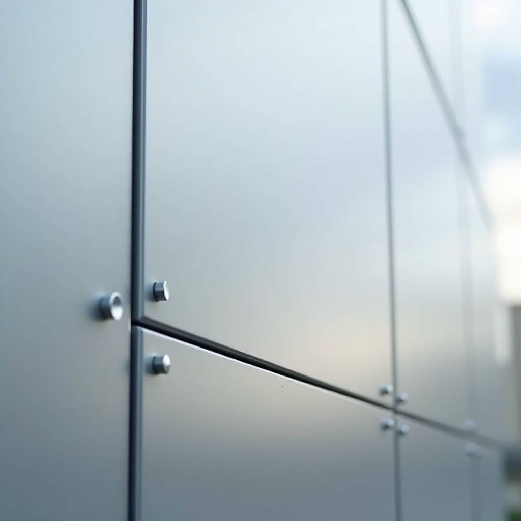
When a curtain wall contractor in Dubai asks whether a 3.0mm solid aluminum panel can span 1,200mm between stiffeners without oil-canning, the answer does not live in a catalog. It lives in the fabrication shop — in the gauge of the brake press, the back-routing depth on the stiffener grid, the sequence of welding, and the thermal history of the PVDF line. Aluminum Panel Fabrication is not simply cutting and folding metal. It is the controlled conversion of flat mill-finish sheet into an engineered, dimensionally stable building skin that must hold its line across decades of thermal cycling, wind load, and UV exposure. This article unpacks the four fabrication decisions that make or break a solid aluminum cladding project: alloy selection, forming methodology, stiffener attachment, and coating process control. Each decision carries cost and performance consequences that procurement teams and facade engineers need to understand before the first sheet hits the CNC router.
Alloy and Temper: The Invisible Foundation of Panel Performance
Not all aluminum is equal, and the differences become painfully visible about 18 months after handover. The starting point for architectural solid aluminum panels is almost always the 3xxx series — specifically 3003-H14 or 3004-H14. These manganese-alloyed grades offer the right balance of formability, corrosion resistance, and moderate strength. Some fabricators push 5052-H32 for high-wind zones or large-format panels, trading a slight penalty in bend radius for a meaningful gain in tensile strength. The choice matters because it dictates everything downstream: the minimum bend radius the brake can achieve without micro-cracking, the springback compensation needed in the flat pattern, and the panel's long-term resistance to thermal creep.
Fabricators who cut corners here reach for 1100-series commercially pure aluminum. It is cheaper, bends easily, and looks identical on the rack. But 1100 carries roughly half the yield strength of 3003-H14. On a 2.5mm panel spanning 900mm between stiffeners, that difference translates to visible deflection under wind suction — the kind that shows up in raking light and generates punch-list items that erode margin. The ASTM B209 standard governs aluminum sheet and plate specifications, and any serious Aluminum Panel Fabrication operation should provide mill certs traceable to the heat number. If the cert says "commercially pure" and the specification called for 3003, the panel will fail — not catastrophically, but cosmetically, which in architectural terms amounts to the same thing.
The temper designation is equally critical. H14 (strain-hardened and partially annealed) is the workhorse. H24 (strain-hardened and partially annealed, but starting from a different initial temper) appears occasionally. The difference is subtle but real: H14 generally offers slightly better flatness retention after routing, which matters when the panel is 1,500mm wide and the architect specified a 5mm joint. At Futeng®, incoming coil is verified against both the alloy spec and the temper before it enters the fabrication line — a step that costs 15 minutes per batch and prevents weeks of rework downstream.
Forming Methodology: Brake Press, Panel Bender, or CNC Folder?
The forming method determines not just the speed of production but the geometry of the panel edge and the consistency of the return leg. Most solid aluminum panel fabrication shops run three types of forming equipment, and the smart ones know which machine to use for which panel geometry.
The hydraulic press brake remains the most flexible option. With properly ground tooling — typically a 0.8mm radius punch for 2.0-3.0mm 3003 material — a skilled operator can produce return legs from 15mm to 150mm with consistent angles. The limitation is operator skill. A 3,000mm-long panel with a 25mm return leg requires the operator to support the sheet through the full bend cycle. If the sheet droops, the bend line wanders, and the panel-to-panel joint alignment suffers. For panels longer than 2,400mm, many fabricators switch to a panel bender — a machine that clamps the sheet and swings the bending leaf, eliminating the sheet-handling variable. The trade-off is that panel benders typically max out at around 200mm on the return leg, and the tooling investment is substantial.
CNC folding centers occupy a middle ground. They handle complex geometries — multiple bends on different edges, partial-height returns, joggle details for interlocking joints — with repeatability that no manual brake can match. But they are slower than a dedicated panel bender on simple rectangular panels. A well-run fabrication shop routes each job to the right machine based on panel dimensions, bend complexity, and volume. The wrong routing decision adds cost without adding value. A 50-panel order of 600mm x 1,200mm simple trays does not belong on a CNC folder; it belongs on a press brake with a back gauge. Conversely, a 20-panel order of faceted trapezoidal panels with compound-angle returns should never touch a manual brake.
One underappreciated variable in forming is the bend deduction calculation. Solid aluminum, unlike steel, has a significant springback factor — typically 2-3 degrees for 3003-H14 at a 90-degree bend with a 0.8mm radius punch. The flat pattern must account for this, or the finished panel dimensions will drift. Shops that rely on rule-of-thumb bend deductions rather than empirically derived tables for each alloy and thickness combination produce panels that fit — mostly. The "mostly" shows up on site, where the installer compensates with joint width variation that the architect notices.
Stiffener Attachment: The Engineering That Nobody Sees
Solid aluminum panels are not inherently stiff. A 2.5mm-thick 1,200mm x 2,400mm sheet, unsupported, will deflect under its own weight when lifted at the corners. The stiffener grid — typically aluminum extrusions of 6063-T5 or 6061-T6 — transforms the panel from a limp sheet into a rigid cassette. The attachment method is where fabrication quality diverges sharply.
The industry standard for high-end work is back-routing and intermittent welding. The stiffener is positioned on the panel back, the fabricator routes a shallow groove through the stiffener flange and into (but not through) the panel face, and then lays a series of 25-40mm stitch welds at 150-200mm centers. The routing depth is critical: 0.3-0.5mm into the panel face for 2.5-3.0mm material. Deeper routing weakens the panel and creates a visible witness line on the face under certain lighting conditions. Shallower routing produces a weak weld that can fail in fatigue under cyclic wind loading.
Some fabricators substitute structural adhesive bonding for welding — either two-part epoxy or acrylic-based systems. Adhesive bonding eliminates the heat-affected zone and the risk of face distortion, and it can be faster in production. The downside is that adhesive performance depends on surface preparation (abrasion and solvent wipe), cure time, and long-term UV and moisture resistance. The AAMA 2605 standard for high-performance organic coatings does not directly address adhesive bonding, so the specifier must evaluate the adhesive system separately. For projects in coastal or high-humidity environments, welded stiffeners remain the more conservative choice.
Another attachment method — mechanical fastening with stainless steel rivets or screws — appears in economy-grade work. It is fast, requires no special equipment, and is easy to inspect. But every fastener is a point load and a potential source of galvanic corrosion if the isolation detail is not perfect. For exposed exterior applications on buildings above three stories, mechanical fastening of stiffeners is generally not recommended by facade engineering consultants. The cost saving on fabrication is quickly consumed by the risk premium on the warranty.
The stiffener layout itself deserves engineering attention. A grid of vertical and horizontal stiffeners at 500-600mm centers is typical for 2.5mm 3003 panels in moderate wind zones. For panels in hurricane-prone regions (design wind speeds above 150 mph per ASCE 7), the spacing may need to tighten to 400mm, and the stiffener section may need to increase from a 25mm x 25mm x 2mm angle to a 38mm x 38mm x 3mm angle. These calculations should be project-specific and stamped by a licensed engineer. The fabricator's role is to execute the engineered design precisely — not to substitute based on what is in stock.
Coating Process Control: PVDF, Powder, and the Finish That Lasts
The coating system is the panel's interface with the environment, and it is where fabrication process control has the most visible consequences. For architectural solid aluminum panels, the dominant specification is PVDF (polyvinylidene fluoride) resin-based coating, applied as a liquid spray system and oven-cured. The relevant standard is AAMA 2605, which sets requirements for color retention, chalk resistance, gloss retention, and film integrity after accelerated weathering.
The coating process starts not with the spray gun but with the pretreatment line. A proper pretreatment sequence for aluminum involves alkaline cleaning, rinsing, chromate conversion coating (or a chromium-free alternative meeting AAMA 2605 requirements), and a final rinse. Each stage must be controlled for concentration, temperature, and dwell time. A panel that skips proper pretreatment will pass visual inspection at the factory and start delaminating at the coating-substrate interface within three to five years. The failure mode is distinctive: the coating peels in sheets, and the exposed aluminum shows no evidence of corrosion — indicating that the coating never bonded in the first place.
After pretreatment, the panel receives a primer coat (typically 5-8 microns dry film thickness), followed by a color coat (25-30 microns DFT) and a clear topcoat (12-15 microns DFT). The total system DFT should be in the range of 42-53 microns for a three-coat system. Some specifications call for a two-coat system (primer plus color) at 30-35 microns total DFT. The three-coat system provides better gloss retention and metallic flake orientation, but it costs more and requires tighter process control to avoid orange peel.
The curing oven is where many problems originate. PVDF coatings require a peak metal temperature (PMT) of 232-249°C for proper cross-linking. If the PMT is too low, the coating is under-cured — it will be soft, prone to scratching, and vulnerable to solvent attack during cleaning. If the PMT is too high, the coating can yellow or the aluminum substrate can anneal, changing the panel's mechanical properties. The oven must be profiled regularly with thermocouples attached to sample panels to verify that the entire load reaches the target PMT range. A fabricator who cannot produce oven profile data for a given batch is guessing.
Powder coating — typically polyester-based — is an alternative for projects where AAMA 2605 performance is not required. AAMA 2604 (high-performance organic coating) and AAMA 2603 (standard performance) define the relevant standards. Powder coating offers faster turnaround, lower cost, and a thicker single-coat film. But its color and gloss retention under UV exposure are inferior to PVDF, particularly for bright colors and metallics. For a building in Phoenix or Singapore, where UV exposure is relentless, the lifecycle cost analysis almost always favors PVDF.
The table below summarizes the key performance differences between these coating systems for solid aluminum panel fabrication:
| Parameter | AAMA 2605 (PVDF 3-Coat) | AAMA 2604 (Polyester Powder) | AAMA 2603 (Polyester Spray) |
|---|---|---|---|
| Minimum Total DFT | 42-53 microns | 60-80 microns | 25-30 microns |
| Color Retention (10yr S. Florida) | Delta E ≤ 5 | Delta E ≤ 8 | No requirement |
| Chalk Resistance (10yr) | Rating ≥ 8 | Rating ≥ 6 | Rating ≥ 4 |
| Gloss Retention (10yr) | ≥ 50% | ≥ 30% | No requirement |
| Typical Warranty Period | 20-30 years | 10-15 years | 5-10 years |
| Relative Cost per sqm | 100% (baseline) | 60-75% | 40-55% |
| Recommended Application | Exterior facade, high-rise | Interior, soffit, low-rise | Interior only, utility |
Quality Control: What to Inspect Before the Panels Ship
Aluminum Panel Fabrication quality control falls into three buckets: dimensional, visual, and performance. Each requires specific tools and acceptance criteria, and the specifier should agree on these before production begins.
Dimensional QC starts with the flat pattern. The fabricator should check the first article against the approved shop drawing at every dimension: overall length and width, return leg depth, stiffener location, and hole/slot positions for the mounting system. Tolerances for solid aluminum panels are typically ±1.5mm on overall dimensions and ±0.5mm on return leg depth for panels up to 1,500mm. For larger panels, the tolerance loosens to ±2.0mm. These numbers come from the practical limits of the forming process and the thermal expansion of the panel — a 3,000mm panel will expand approximately 2.1mm across a 30°C temperature swing, so chasing sub-millimeter accuracy is pointless.
Visual QC covers the coating surface. The standard reference is ASTM D523 for gloss measurement and ASTM D2244 for color measurement. The fabricator should inspect each panel under controlled lighting — typically 500-1,000 lux from a diffuse source — at a viewing distance of 1.5-2.0 meters. Defects that are not visible under these conditions are generally not considered rejectable. Common coating defects include orange peel, dirt inclusion, dry spray, and color variation between panels. The AAMA 2605 standard provides visual comparison standards for these defects, and the specifier should reference them rather than relying on subjective judgment.
Performance QC involves destructive and non-destructive testing. Coating adhesion is tested by the cross-hatch method per ASTM D3359, with a rating of 4B or 5B typically required. Impact resistance is tested per ASTM D2794. For the stiffener welds, a sample of panels (typically 1 per 50 or 1 per batch) should be subjected to a pull-off test to verify weld strength. The test involves attaching a pull-off fixture to the stiffener and applying tensile force until failure. The failure mode should be in the parent metal, not at the weld interface.
One area that deserves more attention than it typically receives is the inspection of the panel edges and corners. The cut edge of a solid aluminum panel is a potential corrosion initiation site, particularly in coastal environments. The PVDF coating does not wrap around the cut edge, so the edge is protected only by the pretreatment layer. For projects within 5km of a marine coastline, the specification should require edge sealing — either a brush-applied touch-up coating or a full edge-wrap detail where the return leg is formed before coating. The latter is more expensive but provides continuous coating coverage across the panel face and return.
Logistics and Handling: Protecting the Fabrication Investment
A perfectly fabricated panel that arrives on site with a dent, a scratch, or a bent corner is a problem. Solid aluminum panels are heavier than ACM — a 2.5mm panel weighs approximately 6.8 kg/m², compared to roughly 5.5 kg/m² for a 4mm ACM panel. That extra mass, combined with the panel's stiffness characteristics, demands specific handling protocols.
Panels should be packed vertically in purpose-built stillages, with interleaving foam or felt separators between each panel face. The stillage should support the panels along their full width, not at point contacts. For export shipments, the stillages should be enclosed in plywood crates with desiccant packs to prevent condensation during ocean transit. The crates should be labeled with the project name, panel type, and a unique identifier that traces back to the fabrication batch records.
On site, the panels should be stored under cover, off the ground, and in their original packing until immediately before installation. If panels must be stored outdoors, they should be covered with breathable tarpaulins — never plastic sheeting, which traps moisture and can cause water staining or coating blisters. The handling team should use suction cup lifters for panels larger than 1m², and they should never lift a panel by one corner or allow it to flex during transport from the storage area to the installation point.
The cost of a damaged panel is not just the replacement fabrication cost. It is the schedule delay while the replacement is produced (typically 3-4 weeks for a custom color), the cost of the crane or access equipment that sits idle, and the ripple effect on the critical path. A 2% damage allowance in the fabrication order is standard practice and far cheaper than the alternative.
Specifying Aluminum Panel Fabrication: What the Documents Should Include
Too many facade specifications treat Aluminum Panel Fabrication as a commodity — a single line item that says "Aluminum cladding panels, 2.5mm, PVDF coated, as per drawings." That level of vagueness invites value engineering that the specifier cannot control. A proper fabrication specification should address at minimum the following:
- Alloy and temper: 3003-H14 or 3004-H14 as baseline; 5052-H32 for high-wind or large-format applications.
- Sheet thickness: 2.0mm minimum for interior soffits; 2.5mm standard for exterior; 3.0mm for panels exceeding 1.5m² or in high-wind zones.
- Stiffener material: 6063-T5 or 6061-T6 extruded aluminum, with section size determined by engineering calculation.
- Stiffener attachment: Back-routed and stitch-welded, with routing depth not exceeding 0.5mm into the panel face.
- Coating system: AAMA 2605 three-coat PVDF, with primer, color coat, and clear topcoat. Minimum total DFT 42 microns.
- Pretreatment: Chromate conversion coating per ASTM B449, or chromium-free alternative with documented equivalence.
- Quality control: First-article inspection, dimensional check per ISO 2768-m, visual inspection per AAMA 2605, adhesion test per ASTM D3359.
- Documentation: Mill certs for the aluminum, oven profile data for the coating, QC reports for each batch.
The specification should also require the fabricator to submit a fabrication plan that describes the routing of each panel type through the shop — which machine, which tooling, which inspection gate. This document is not a formality. It reveals whether the fabricator has thought through the job or is planning to figure it out on the shop floor.
For projects in the Middle East, Southeast Asia, or other regions where the supply chain crosses international borders, the specification should address the logistics plan as well. Who is responsible for the stillages? What is the packing standard for ocean freight? What is the procedure for documenting and replacing transit-damaged panels? These questions are tedious in the specification phase and critical during the execution phase.
The American Architectural Manufacturers Association (AAMA) publishes the standards referenced throughout this article. The ASTM International standards for aluminum sheet (B209), coating adhesion (D3359), and impact resistance (D2794) are available directly. The ISO 2768 general tolerances standard provides a useful reference for dimensional acceptance criteria. For wind load calculations, ASCE 7 is the governing standard in the United States and is widely referenced internationally. These documents form the technical backbone of any defensible Aluminum Panel Fabrication specification.
Solid aluminum panel fabrication is a discipline that rewards specificity. The difference between a facade that performs for 30 years and one that generates warranty claims in year three is rarely a single catastrophic error. It is the accumulation of small decisions: the alloy that was almost right, the weld that was almost deep enough, the oven that was almost at temperature, the packing that was almost adequate. Each decision is made on the shop floor, and each one is controllable if the specification is clear and the QC is rigorous. For procurement teams and facade engineers, the task is not to micromanage the fabricator. It is to define the outcome with enough precision that the fabricator knows exactly what "good" looks like — and then to verify that it was delivered.