Anodized Aluminium Panel Wind Load Engineering and Alloy Selection for High Rise Facades
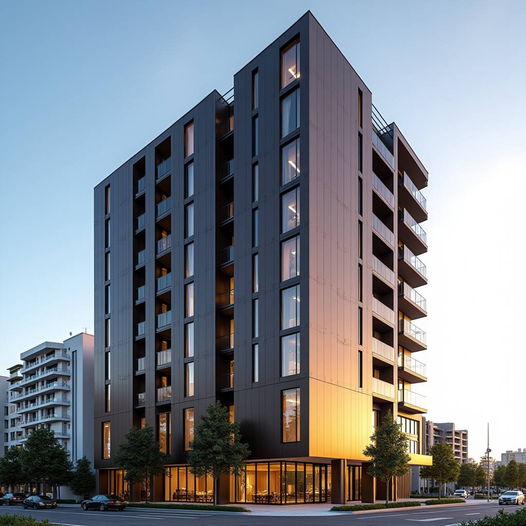
Anodized Aluminium Panel systems occupy a distinct position in the facade industry, and the question that keeps resurfacing from contractors and specifiers alike is straightforward: can these panels maintain dimensional stability and color consistency when installed on high-rise structures subjected to severe wind loads? The short answer is yes, but only when the alloy temper, anodizing bath chemistry, and substructure engineering are treated as a single integrated system rather than three separate purchasing decisions. Over the last decade, I have walked enough job sites across Southeast Asia and the Middle East to know that the failures rarely trace back to the anodized layer itself. They trace back to decisions made six months earlier on a spreadsheet, where someone substituted a cheaper temper or shaved 0.3mm off the panel thickness without recalculating the deflection limits. This article breaks down what actually matters when specifying Anodized Aluminium Panel facades for wind-critical buildings: the numbers behind flexural rigidity, the overlooked role of interlayer heat buildup, and the QA protocols that separate a 30-year facade from one that starts showing oil-canning within the first monsoon season.
Why Wind Load Performance Demands More Than a Thick Panel
Most spec sheets for Anodized Aluminium Panel products list a thickness, a yield strength, and a generic "wind load resistance" value. On a real building, those three numbers barely scratch the surface. Wind pressure on a facade is not uniform. It peaks at corners, edges, and parapets, where negative suction pressures can reach 2.5 to 3.0 times the magnitude of the positive pressure on the building's mid-span. The American Society of Civil Engineers standard ASCE 7-22 provides pressure coefficient maps that make this painfully clear: a panel that works perfectly at the building centerline may be under-specified by a factor of two at the corner zone.
The immediate temptation is to increase panel thickness. Going from 2.0mm to 3.0mm solid aluminium adds roughly 50% more material, but the flexural stiffness increase is not linear with thickness. For a rectangular plate under uniform pressure, the maximum deflection is inversely proportional to the cube of the thickness. That means a 3.0mm panel deflects roughly 70% less than a 2.0mm panel under identical loading. But thickness alone cannot compensate for poor alloy selection. An Anodized Aluminium Panel fabricated from a 5052-H32 alloy will deliver markedly different deflection behavior than one made from 3003-H14, even at identical thickness. The magnesium content in 5052 (around 2.5%) boosts tensile strength to approximately 230 MPa, compared to roughly 150 MPa for 3003. When wind gusts hit a facade, what matters is the combination of thickness, alloy grade, temper, and the span between fixing points. Ignore any one of those variables and the math falls apart.
Alloy Selection: The Foundation Nobody Discusses in the Spec Room
Architects spend hours debating the shade of an anodized bronze versus a clear silver finish. Meanwhile, the alloy designation buried in Section 05 40 00 of the specification determines whether those panels will still look flat after five years of thermal cycling. For solid Anodized Aluminium Panel applications on exterior facades, three alloy families dominate the market: 1xxx (commercially pure), 3xxx (Al-Mn), and 5xxx (Al-Mg).
The 1xxx series, specifically 1100-H14, anodizes beautifully. The nearly pure aluminium (99.0% minimum) produces an oxide layer with exceptional clarity and color consistency. The problem is mechanical: yield strength hovers around 95-125 MPa, which means panel deflections under wind load become the governing design constraint long before the material approaches its ultimate tensile limit. For low-rise buildings in sheltered locations, 1100 anodized panels can work. For anything above four stories or within 50 kilometers of a coastline, the required thickness to control deflection typically makes the system cost-prohibitive.
The 3xxx series, primarily 3003-H14, offers a practical middle ground. It anodizes acceptably, though the manganese content (1.0-1.5%) can produce a slightly warmer tone in the oxide layer that varies between batches. Yield strength at 145 MPa provides a meaningful stiffness improvement over 1100. For mid-rise commercial buildings, 3003-H14 remains the most commonly specified alloy for Anodized Aluminium Panel cladding, largely because it balances formability, cost, and anodizing response.
The 5xxx series, specifically 5052-H32, is where serious wind-load engineering begins. Yield strength of 195 MPa and tensile strength of 230 MPa mean that a 2.5mm 5052 panel can often replace a 3.0mm 3003 panel, saving weight without sacrificing stiffness. The trade-off is anodizing behavior. Magnesium-rich intermetallic phases at the surface can produce a slightly more diffuse oxide layer, and achieving a perfectly uniform dark bronze across a large batch of 5052 panels requires tighter process control at the anodizing line. This is where a supplier like Futeng®, with dedicated anodizing tank lines calibrated for 5xxx alloys, becomes relevant to the procurement conversation. The engineering team knows that the same 20-micron oxide thickness specification produces different visual results on 5052 versus 3003, and they adjust bath parameters accordingly.
Oxide Layer Thickness and the AAMA 611 Standard
The architectural anodizing industry operates under AAMA 611, the voluntary specification for anodized architectural aluminum. This standard defines Class I and Class II anodized coatings. Class I, the high-performance designation, requires a minimum oxide thickness of 18 microns (0.7 mils). Class II permits a minimum of 10 microns (0.4 mils). For exterior Anodized Aluminium Panel facades, Class I is the only defensible choice. A 10-micron oxide layer simply cannot withstand decades of UV exposure, acid rain, and salt spray without color shift and eventual chalking.
But here is the detail that separates a specification from a working facade: oxide thickness alone does not guarantee weather resistance. The sealing quality matters equally. Anodized aluminium develops a porous oxide structure during the electrolytic process. Those pores must be sealed, typically through hydrothermal sealing in deionized water at 96-100°C, or through mid-temperature sealing with nickel acetate. An improperly sealed 20-micron oxide layer will absorb contaminants and lose its color stability faster than a properly sealed 15-micron layer. The AAMA 611 standard includes a modified stain test (ASTM D3359) and an acid dissolution test (ASTM B680) specifically to verify seal quality. If your panel supplier cannot produce test certificates for both oxide thickness and seal quality on the same batch of Anodized Aluminium Panel material, find another supplier.
The Thermal Factor: How Heat Builds Inside the Cavity
Wind load analysis tends to dominate the structural conversation, but thermal movement is the silent partner that amplifies every stress concentration. An Anodized Aluminium Panel with a dark bronze or black finish can reach surface temperatures of 80-85°C under direct summer sun in the Middle East or Southeast Asia. The aluminium substrate expands at roughly 24 × 10⁻⁶ per °C. For a 3-meter panel length subjected to a 60°C temperature swing (from 25°C night to 85°C day), the linear expansion is approximately 4.3mm. If the fixing system does not accommodate that movement, the panel will buckle.
The problem compounds when the ventilated cavity behind the panel traps heat. A rainscreen system with a 50mm air gap behind an Anodized Aluminium Panel can see cavity temperatures 15-20°C higher than ambient air temperature. This heat buildup affects the panel substrate, the aluminium substructure, and the thermal insulation layer simultaneously. The differential expansion between the aluminium panel and the steel or aluminium support rails creates shear forces at the fixing points. Over thousands of thermal cycles, these forces can loosen fasteners, elongate fixing holes, and eventually produce the characteristic "oil-canning" distortion that makes a facade look wavy even when the wind is calm.
The engineering countermeasure is not complicated, but it requires discipline. Panel lengths should be limited to approximately 3.0-3.5 meters for dark anodized finishes unless expansion joints are explicitly designed into the system. Fixing points should use slotted holes oriented to permit movement in the panel's long axis. The coefficient of thermal expansion for the substructure material should be matched as closely as possible to the panel material. Aluminium substructures paired with Anodized Aluminium Panel facades eliminate the differential expansion problem entirely, which is why they are the standard recommendation for high-thermal-stress environments.
Deflection Limits: Why L/175 Is Not a Universal Answer
Industry practice for aluminium cladding panels frequently cites L/175 as the allowable deflection limit under design wind load, where L is the span between fixing points. This number comes from a reasonable place: it keeps panel deflection below the threshold where the human eye can perceive waviness under diffuse lighting. But L/175 is a guideline, not a law, and it fails in two specific scenarios.
First, when the Anodized Aluminium Panel has a highly reflective finish. Clear anodized and light bronze finishes act as mirrors under direct sunlight. A deflection of L/200 can be visible as a distortion in the reflected image, even though the physical displacement is well within structural limits. For high-gloss anodized finishes on prominent facades, tightening the deflection limit to L/240 or even L/300 is a prudent specification upgrade that costs nothing in material but prevents a lot of post-installation arguments about "wavy panels."
Second, when the panel aspect ratio departs significantly from square. A long, narrow panel spanning 1.2 meters between vertical rails but measuring 3.6 meters in length will exhibit different deflection behavior than a 1.2 × 1.2 meter panel. The two-way bending action that stiffens a square panel diminishes as the aspect ratio increases, and the panel begins to behave more like a one-way beam. The L/175 limit assumes two-way bending. For aspect ratios above 3:1, a more conservative limit of L/200 or a detailed finite element analysis is warranted.
The following table summarizes the recommended deflection limits for Anodized Aluminium Panel applications based on finish type, building height, and exposure category. These values are derived from field observations across multiple projects and are offered as practical engineering guidance rather than code mandates.
| Building Condition | Finish Type | Recommended Deflection Limit | Panel Aspect Ratio Limit | Minimum Alloy Recommendation |
|---|---|---|---|---|
| Low-rise, sheltered (0-15m) | Matte / Light Bronze | L/175 | Up to 4:1 | 3003-H14 |
| Mid-rise, urban (15-50m) | Clear / Medium Bronze | L/200 | Up to 3:1 | 3003-H14 or 5052-H32 |
| High-rise, exposed (50m+) | Dark Bronze / Black | L/240 | Up to 2.5:1 | 5052-H32 |
| Coastal, any height | Any anodized | L/200 minimum | Up to 3:1 | 5052-H32, Class I only |
| High-gloss architectural feature | Clear / Light Bronze | L/300 | Up to 2:1 | 5052-H32 |
Fixing System Design: The Hidden Cost Driver
The substructure and fixing method for an Anodized Aluminium Panel facade typically accounts for 35-45% of the total installed cost, yet it receives disproportionately little attention during the value engineering process. Three fixing systems dominate the market: exposed rivet systems, cassette systems with hidden clips, and tray panels with rear-rail support. Each interacts differently with wind loads.
Exposed rivet systems are the most economical and the most widely used in industrial and low-budget commercial projects. The panel is fixed directly to the substructure with aluminium or stainless steel rivets at 300-400mm centers. The advantage is simplicity and speed of installation. The disadvantage is that every rivet hole is a stress concentration point. Under cyclic wind loading, the aluminium around the rivet hole can work-harden and eventually crack, particularly if the rivet was over-driven during installation. For buildings in typhoon or hurricane zones, exposed rivet fixing should be limited to panel sizes under 1.5 square meters unless the panel edge distance and rivet diameter have been specifically engineered for the load case.
Cassette systems with hidden clips eliminate the visible fastener problem and distribute wind loads more evenly across the panel perimeter. The folded return edges of the cassette engage with aluminium clips that are fixed to the substructure. This creates a continuous support condition along all four edges, which dramatically improves the panel's resistance to wind-induced deflection. The trade-off is cost: cassette fabrication requires CNC folding equipment and tighter dimensional tolerances, and the installation is slower. For an Anodized Aluminium Panel cassette system on a 10,000-square-meter facade, the cost premium over exposed rivet fixing can range from 25-40%, depending on panel complexity and local labor rates.
Tray panels with rear-rail support represent the high end of the performance spectrum. The panel is bonded or mechanically fixed to an aluminium rail system on its rear face, and the rails are then hung from the substructure. This decouples the panel's thermal movement from the building structure and allows for individual panel replacement without disturbing adjacent panels. The system is common in high-end commercial towers and institutional buildings where maintenance access is a long-term consideration. The installed cost is typically 50-70% above an exposed rivet system, but the lifecycle cost can be lower when factoring in reduced maintenance and easier panel replacement over a 30-year service life.
QA Protocols That Catch Problems Before Installation
The quality assurance process for Anodized Aluminium Panel procurement should begin at the anodizing line, not at the receiving dock. Three specific tests deserve a place in every project specification, and they should be performed on samples drawn from the actual production batch, not from a pre-qualification sample submitted months earlier.
First, the coating mass test per ASTM B137 determines the weight of the anodic oxide layer per unit area. This is a destructive test that strips the oxide layer and measures the mass difference. For Class I architectural anodizing, the minimum coating mass is 0.43 mg/cm², corresponding to approximately 18 microns. The test should be performed on a minimum of three samples per batch, and the results should be recorded and traceable to the panel serial numbers.
Second, the seal quality test per ASTM B680 uses an acid dissolution method to measure the rate at which the sealed oxide layer dissolves in a chromic-phosphoric acid solution. A properly sealed Anodized Aluminium Panel will show a mass loss of no more than 2.0 mg/cm² after 15 minutes of immersion. Values above 3.0 mg/cm² indicate incomplete sealing and a high risk of premature color fading and corrosion staining.
Third, the UV accelerated weathering test per ASTM G154 provides a comparative measure of color stability. Panels are exposed to alternating cycles of UV radiation and condensation for a minimum of 1,000 hours. The color change (ΔE) measured per ASTM D2244 should not exceed 5.0 for dark colors and 3.0 for light colors. This is particularly critical for Anodized Aluminium Panel installations in tropical and high-altitude locations where UV exposure is intense.
Beyond laboratory tests, a simple field inspection protocol can catch the majority of installation defects. After the first 200 square meters of panels are installed, the facade should be inspected under low-angle morning or late-afternoon light, which reveals surface waviness and oil-canning that overhead midday sun masks. Any panel showing visible distortion should be measured with a straightedge and feeler gauge. Deflections exceeding 2mm over a 1-meter span at zero wind load indicate a problem with the fixing system or panel flatness that will not improve with time.
Coastal Environments: When Salt Spray Rewrites the Rules
Coastal installations within 5 kilometers of breaking surf impose a set of requirements on Anodized Aluminium Panel systems that inland projects can safely ignore. The combination of chloride ions, high humidity, and UV radiation accelerates the degradation of underspecified anodized finishes at a rate that surprises even experienced contractors.
The primary failure mode is pitting corrosion initiating at imperfections in the oxide layer. Salt spray testing per ASTM B117 demonstrates that Class I anodized coatings (18+ microns) on 5xxx series alloys can withstand 1,000+ hours of salt spray exposure without significant pitting, while Class II coatings (10 microns) on 3xxx alloys may show pitting within 300-500 hours. For buildings within 500 meters of the shoreline, an additional layer of protection is advisable: specifying a minimum oxide thickness of 25 microns, which exceeds the Class I minimum by nearly 40%. Some anodizing facilities can achieve this with extended bath times, though it adds approximately 10-15% to the finishing cost.
The substructure material choice in coastal environments also shifts. Galvanized steel substructures, common in inland projects, will corrode in a marine atmosphere within 5-10 years regardless of the coating specification. Stainless steel grade 316 or all-aluminium substructures are the only viable options for coastal Anodized Aluminium Panel facades. The cost premium for 316 stainless brackets and fasteners over galvanized steel is approximately 30-40%, but the alternative is a facade that requires substructure replacement within a decade.
The American Architectural Manufacturers Association (AAMA) publishes technical information reports that address coastal material selection. The ISO 9227 standard for salt spray testing provides the methodology for comparative corrosion resistance evaluation. For projects in the Middle East Gulf region, the combination of salt spray and sand abrasion creates a uniquely aggressive environment that demands both high oxide thickness and regular cleaning protocols to remove salt deposits before they can initiate corrosion cells.
Color Consistency Across Production Batches
Anodizing is an electrochemical process, not a paint application. The color of an Anodized Aluminium Panel depends on the alloy composition, the anodizing bath chemistry (sulfuric acid concentration, temperature, current density), the dye bath parameters if colored, and the sealing method. Variation in any of these parameters shifts the final color. For a project requiring 5,000 square meters of panels produced over three months, achieving batch-to-batch color consistency is arguably the hardest quality control challenge in the entire supply chain.
The industry standard for color measurement is the CIE L*a*b* system, with tolerances typically specified as ΔE ≤ 2.0 for adjacent panels and ΔE ≤ 3.0 for panels on different elevations. These numbers sound tight, and they are. A ΔE of 2.0 is barely perceptible to the human eye under controlled lighting, but on a facade under natural daylight, even a ΔE of 1.5 can be visible if the panels are adjacent and the light hits them at a glancing angle.
The practical solution involves three measures. First, the entire project quantity should be anodized as a single production campaign whenever possible, using the same anodizing tank and the same bath chemistry. Second, the raw aluminium coil or sheet stock should come from a single heat lot to minimize alloy composition variation. Third, the panels should be numbered and a facade map should be prepared before installation, so that any subtle color variation is distributed across the facade rather than concentrated in a single visible area. These measures add administrative complexity but cost almost nothing compared to the expense of removing and replacing panels that the architect rejects for color mismatch.
Supply Chain Realities: Lead Times and Regional Capacity
Procurement managers dealing with Anodized Aluminium Panel specifications quickly learn that anodizing capacity is the bottleneck. The global supply chain for architectural anodizing is concentrated in a relatively small number of facilities with tanks large enough to handle panel sizes of 1.5 meters by 4 meters or larger. Lead times for custom anodized panels typically range from 6 to 14 weeks, depending on the facility's backlog and the complexity of the finish specification.
Standard clear anodized and light bronze finishes are available from multiple suppliers with lead times at the lower end of that range. Dark bronze, black, and custom-dyed colors require dedicated tank runs and can push lead times to the upper end. The lesson for project scheduling is that the anodized finish specification should be locked in at least 16 weeks before panels are required on site. Changing the color specification after the anodizing run has begun will add 4-6 weeks to the schedule and may require re-qualification of the entire batch.
For projects in regions without local architectural anodizing capacity, the logistics of shipping finished Anodized Aluminium Panel products add another layer of complexity. The panels cannot be stacked directly against each other without interleaving protective film, and the film must be UV-stable if the panels will be stored outdoors for more than a few weeks. Ocean freight from anodizing facilities in East Asia to project sites in the Middle East or Europe typically adds 4-6 weeks of transit time, plus customs clearance. The protective film should be specified as a UV-resistant, low-adhesion polyethylene film that removes cleanly after 6 months of outdoor exposure, because project delays are the rule rather than the exception.
Making the Specification Stick: What to Write in Section 05 40 00
The most technically sound Anodized Aluminium Panel specification is worthless if it cannot be enforced during construction. Three clauses belong in every architectural specification for anodized aluminium cladding, and they should be written as pass/fail requirements rather than aspirational guidelines.
First, the alloy and temper designation must be stated explicitly with no substitutions permitted without engineer-of-record approval. "Aluminium alloy 5052-H32 per ASTM B209" leaves no room for interpretation. "Aluminium alloy 3003-H14 or equivalent" invites the contractor to propose a cheaper alternative that may not meet the deflection criteria.
Second, the anodizing specification must reference AAMA 611 Class I and include the specific oxide thickness, seal quality test method, and color tolerance. The phrase "anodized finish" alone is not a specification; it is a wish. The spec should read: "Architectural Class I anodized finish per AAMA 611, minimum oxide thickness 18 microns (ASTM B137), seal quality per ASTM B680 with maximum mass loss 2.0 mg/cm², color tolerance ΔE ≤ 2.0 per ASTM D2244."
Third, the specification must include a requirement for a performance mock-up. A minimum of 20 square meters of the Anodized Aluminium Panel system, including the substructure, fixings, and all perimeter details, should be erected on site or at a testing facility and subjected to the design wind pressure per ASTM E330. The mock-up should be inspected for deflection, permanent deformation, and fastener distress. This test costs money and time, but it costs far less than discovering a systemic problem after 3,000 square meters are already installed.
The ASTM B209 standard for aluminium sheet and plate, the ASTM E330 standard for structural performance testing, and the Aluminum Association design manual collectively provide the technical foundation for a defensible specification. The engineering judgment lies in applying these standards to the specific wind environment, thermal conditions, and aesthetic requirements of each project.
Anodized Aluminium Panel facades engineered with attention to alloy selection, oxide thickness, deflection limits, and thermal movement accommodation will perform reliably for 30 years or more. The failures I have investigated over the years share a common thread: someone along the chain treated the anodized finish as a commodity and the structural engineering as an afterthought. The finish and the structure are one system. Specify them together, test them together, and the facade will do its job without drama.