Fluorocarbon Coated Aluminum Panel AAMA 2605 Compliance and PVDF Coating System Technical Specification
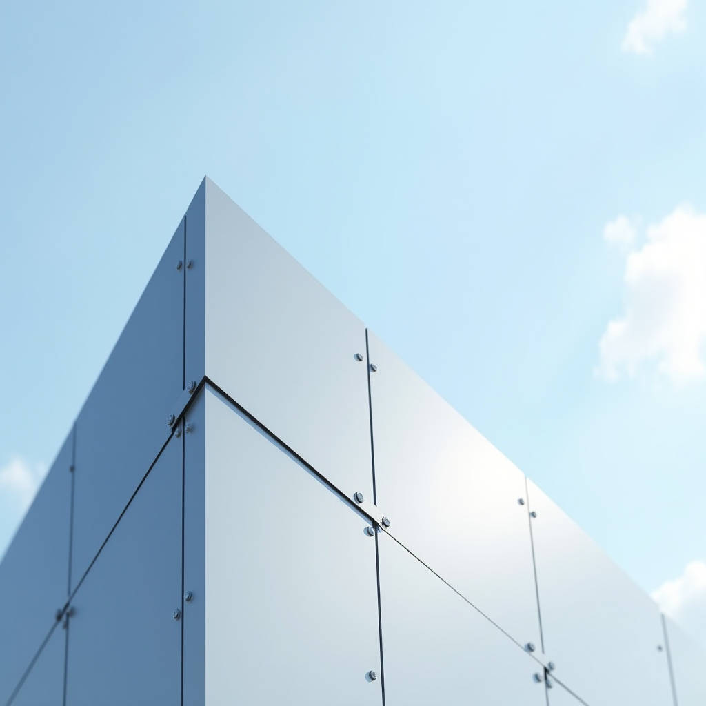
When a curtain wall consultant stamps a specification requiring AAMA 2605 compliance, they are not asking for a generic factory finish. They are mandating a Fluorocarbon Coated Aluminum Panel system built on 70% PVDF resin chemistry, a baked film measured in microns, and a performance warranty that must hold across 25 years of UV exposure, salt spray, and industrial fallout. The distinction between a panel that merely looks acceptable on day one and one that still reads within 3 Delta E units of its original color two decades later sits entirely in the coating formulation, pretreatment sequence, and cure cycle. This article examines the technical chain that separates compliant PVDF-coated solid aluminum cladding from under-specified alternatives, with particular attention to film thickness verification, accelerated weathering correlation, and the fabrication tolerances that determine whether a project passes punch-list inspection or generates a dispute.
What the AAMA 2605 Label Actually Requires
AAMA 2605 is not a single test. It is a performance specification that bundles nine separate laboratory procedures, each designed to stress a different failure mode of the organic coating system. For a Fluorocarbon Coated Aluminum Panel to carry the 2605 designation, the coating must survive 4,000 hours of salt spray (ASTM B117) with no blistering and less than 1/16-inch creep from scribe, 10 years of South Florida exposure with color retention above 5 Delta E, and 4,000 hours of humidity resistance (ASTM D2247) with no formation of blisters larger than No. 8 size. The spec also requires minimum film thickness: 1.2 mils (30 microns) for a two-coat system, 1.5 mils (38 microns) for three-coat, and 1.8 mils (46 microns) for four-coat, with the topcoat alone carrying the PVDF resin.
The resin chemistry matters because not all fluoropolymers are equal. A legitimate 70% PVDF coating uses Kynar 500® or Hylar 5000® resin as the binder, with the remaining 30% consisting of acrylic modifiers and pigment dispersions. The acrylic component is necessary for adhesion and pigment wetting, but any formulation that drops below 70% PVDF sacrifices the carbon-fluorine bond density that gives the coating its ultraviolet inertness. Independent lab analysis can verify resin content through Fourier-transform infrared spectroscopy (FTIR), and experienced specifiers increasingly request batch-level FTIR reports alongside standard physical test certificates.
Pretreatment: The Layer Nobody Sees
Before a single micron of PVDF topcoat reaches the aluminum substrate, the metal surface must undergo a conversion coating that creates a chemically bonded interface. The industry standard for architectural aluminum is a hexavalent-chromium or trivalent-chromium chromate conversion coating applied in a multi-stage immersion or spray line. The chromium compounds react with the aluminum oxide layer to form a complex chrome-aluminum matrix that provides two functions: it passivates the surface against filiform corrosion and it creates a microscopically rough anchor profile for the primer layer.
Chromate coating weight is measured in milligrams per square foot, typically 15-25 mg/ft² for architectural applications. Below 10 mg/ft², the corrosion protection drops sharply. Above 40 mg/ft², the coating becomes electrically resistive and can interfere with the electrostatic spray application of the primer. The pretreatment line must also include a deoxidizing stage to remove smut and a cascade rinse system that keeps final-rinse conductivity below 30 microsiemens. Any residual chloride or sulfate on the surface before priming becomes a corrosion initiation site, regardless of how thick the PVDF topcoat is applied.
Film Build: Two-Coat, Three-Coat, and Four-Coat Systems
The coating architecture for a Fluorocarbon Coated Aluminum Panel is not a single sprayed layer. It is a stratified system where each layer performs a distinct function. The primer, typically an epoxy or polyurethane-based formulation, provides adhesion to the chromate conversion coating and serves as the primary corrosion barrier. The color coat carries the PVDF resin, the pigment, and the UV-absorbing package. In three-coat and four-coat systems, a clear PVDF topcoat adds additional film thickness, gloss control, and a sacrificial UV-absorbing layer that protects the color coat from photo-oxidation.
Film thickness verification on the production line uses eddy-current gauges calibrated to the specific aluminum alloy. Measurements are taken on every panel at multiple points, and the data is recorded against the panel serial number. The table below summarizes the typical film build specifications for each system type, based on AAMA 2605 requirements and common architectural practice.
| Coating System | Primer (mils/µm) | Color Coat (mils/µm) | Clear Coat (mils/µm) | Total DFT (mils/µm) | Typical Application |
|---|---|---|---|---|---|
| Two-Coat (Primer + Color) | 0.2-0.3 / 5-8 | 1.0-1.2 / 25-30 | N/A | 1.2-1.5 / 30-38 | Interior walls, soffits, sheltered areas |
| Three-Coat (Primer + Color + Clear) | 0.2-0.3 / 5-8 | 0.8-1.0 / 20-25 | 0.5-0.7 / 12-18 | 1.5-2.0 / 38-50 | Standard exterior facades, curtain walls |
| Four-Coat (Primer + Barrier + Color + Clear) | 0.2-0.3 / 5-8 | 0.8-1.0 / 20-25 | 0.7-1.0 / 18-25 | 1.8-2.5 / 46-63 | Coastal zones, high-pollution industrial areas |
The four-coat system introduces a barrier coat between the primer and the color coat. This barrier layer, typically a PVDF-acrylic blend without pigment, serves as an additional corrosion shield and improves the color uniformity of metallic and mica finishes by providing a consistent base reflectance. For projects within 500 meters of breaking surf or in regions with combined high humidity and industrial SO₂ emissions, the four-coat specification is increasingly treated as the baseline rather than an upgrade.
Accelerated Weathering vs. Real-World Performance
QUV-B and Xenon arc weathering chambers produce data in weeks, but the correlation between accelerated testing and actual facade performance is not linear. AAMA 2605 requires 10-year South Florida exposure at 45° south-facing, which is the gold standard for real-time weathering data. The Florida environment delivers approximately 280 MJ/m² of annual UV radiation, high humidity, and nighttime condensation cycles that drive moisture into any micro-crack in the coating film.
The failure mode that separates quality PVDF coatings from underperformers is not catastrophic peeling but chalking. Chalking occurs when the organic binder at the coating surface photo-degrades, releasing pigment particles as a fine powder that can be wiped off with a finger. AAMA 2605 permits a maximum chalking rating of No. 8 (ASTM D4214) after 10 years. In practice, a properly formulated 70% PVDF Fluorocarbon Coated Aluminum Panel should hold at No. 9 or No. 10 for the full 10-year period, with measurable chalking only beginning to appear in years 15-20. The carbon-fluorine bond energy of approximately 485 kJ/mol is higher than the photon energy of solar UV radiation at the earth's surface, which is the fundamental physical reason PVDF outperforms polyester and polyurethane coatings.
Color Consistency and the Delta E Problem
Architects specify a RAL, Pantone, or custom color, and expect every panel on the facade to match. The reality of PVDF coating production is that color is a function of film thickness, pigment dispersion, bake temperature, and substrate preparation. A variation of 0.2 mils in color coat thickness can shift the perceived color of a metallic finish by more than 1 Delta E unit. The cure oven temperature profile, which typically ramps from 230°C to 250°C peak metal temperature over 8-12 minutes, must be uniform across the entire panel surface to avoid color drift between the center and edges.
Quality-focused manufacturers, including suppliers like Futeng®, implement spectrophotometric quality control at multiple stages: incoming pigment batch verification, wet-coating color measurement, post-cure panel measurement, and final assembly inspection under controlled D65 illumination. The production tolerance for a single batch is typically held to less than 1.0 Delta E (CIE Lab, D65/10° observer), while batch-to-batch tolerance for the same project is maintained under 2.0 Delta E. For large facade projects exceeding 10,000 square meters, the specification should require a single production run or documented color continuity protocols between runs.
Fabrication After Coating: The Edge Condition Problem
Solid aluminum panels are cut, routed, bent, and perforated after the coil or sheet has been coated. This means every cut edge, every punched hole, and every routed groove exposes bare aluminum that is no longer protected by the PVDF system. The corrosion risk at these edges is managed through several strategies. For panels fabricated from pre-coated coil, the cut edges on the interior face are typically hidden within the perimeter extrusion or behind gaskets, and the exposed cut edge area is small relative to the total coated surface. For panels that require post-fabrication touch-up, a two-component PVDF air-dry repair coating can be applied to cut edges, though the repair coating will never achieve the same film integrity as the factory-baked system.
The perforated panel application deserves special attention. When a Fluorocarbon Coated Aluminum Panel is perforated with thousands of holes for acoustic or decorative purposes, each hole creates a cylindrical cut surface through the coating. The total exposed aluminum area can be significant. The industry approach is to specify that perforations be made before coating whenever possible, with the liquid PVDF spray penetrating the hole interiors during application. When perforation must occur after coating, a chromate conversion coating dip or a PVDF clear coat dip for the entire panel after perforation can restore corrosion protection to the hole interiors.
Substrate Alloy and Temper Selection
The aluminum substrate beneath the fluorocarbon coating is not a generic material. Architectural cladding typically uses 3003-H14, 5005-H14, or 5052-H32 alloys, each with different strength, formability, and corrosion resistance characteristics. Alloy 3003-H14 offers good formability for complex panel geometries and has a tensile strength of approximately 150 MPa. Alloy 5052-H32 provides higher strength (230 MPa tensile) and superior resistance to marine atmospheric corrosion due to its magnesium content, making it the preferred substrate for coastal projects. The alloy selection affects the panel's flatness tolerance, its ability to resist oil-canning under thermal cycling, and its long-term corrosion behavior if the coating is ever breached.
For 2.0mm, 2.5mm, and 3.0mm solid aluminum panels—the standard thicknesses for architectural cladding—the flatness tolerance after fabrication should not exceed 0.8% of the panel diagonal dimension for 5005-H14, measured per ASTM E1030. A 1,200mm x 2,400mm panel with a diagonal of approximately 2,683mm should show no more than 21mm of deviation from a flat plane. Achieving this tolerance requires not only correct alloy and temper selection but also proper stress-relief during the coating bake cycle and careful handling during fabrication to avoid introducing residual stress.
Thermal Movement and Panel Joint Design
A solid aluminum panel with a PVDF coating will expand and contract with temperature changes at a rate of approximately 2.4mm per meter per 100°C of temperature change. On a dark-colored panel in a desert climate, the surface temperature can swing from 5°C at night to 80°C under direct solar radiation, producing a thermal movement of roughly 1.8mm per meter. The joint design between panels must accommodate this movement without binding, buckling, or transferring stress to the coating at panel edges.
The standard joint width for Fluorocarbon Coated Aluminum Panel facades is 10-20mm, with the exact dimension calculated based on panel size, color, climate zone, and the thermal expansion coefficient of the supporting subframe. Open-joint systems (rainscreen) allow air circulation behind the panel, which reduces the temperature differential and the associated thermal movement. Closed-joint systems with wet-seal gaskets require wider joints and more careful calculation because the sealant itself imposes movement constraints. The joint design also affects the visual appearance of the facade: a 15mm shadow gap reads differently at 20 meters than at 5 meters, and the specifier should review full-scale mockups under natural lighting conditions before finalizing joint dimensions.
Specifying PVDF Coatings for Coastal and Industrial Environments
Marine environments combine three aggressive factors: chloride ion deposition, high relative humidity, and UV radiation. The chloride ions from sea spray can penetrate micro-defects in the coating and initiate pitting corrosion on the aluminum substrate if the pretreatment layer is inadequate. Industrial environments add sulfur dioxide and nitrogen oxides, which combine with atmospheric moisture to form acidic solutions that attack the coating surface. AAMA 2605 does not have a separate coastal or industrial classification, so the specifier must add project-specific requirements to the base specification.
For coastal projects, the minimum recommendation is a four-coat PVDF system on 5052-H32 alloy with a minimum total dry film thickness of 2.0 mils (50 microns). The chromate conversion coating weight should be at the upper end of the standard range, 25-35 mg/ft². For industrial environments with documented SO₂ levels above 20 µg/m³ annual average, the specification should require a minimum of five years of accelerated cyclic corrosion testing per ISO 12944-6, C4 or C5 classification, in addition to the standard AAMA 2605 test suite. The American Architectural Manufacturers Association publishes technical interpretation documents that provide guidance on environmental severity classification.
Quality Assurance Documentation and Batch Traceability
A Fluorocarbon Coated Aluminum Panel shipment should arrive with a documentation package that enables full traceability from the aluminum ingot to the finished panel. The minimum documentation set includes: mill test certificates for the aluminum coil or sheet (showing alloy, temper, mechanical properties, and chemical composition per ASTM B209), pretreatment process logs (showing bath chemistry, temperature, and dwell time for each stage), coating application records (showing film thickness measurements per panel, oven temperature profiles, and paint batch numbers), and final inspection reports (showing color measurements, gloss readings, and visual inspection results).
The paint batch number is the critical link in the traceability chain. Each batch of PVDF liquid coating is formulated to a specific color standard and has a defined pot life and application window. If a project requires multiple paint batches, the batch numbers must be documented against the panel serial numbers so that any color variation observed during installation can be traced to its source. The ASTM International standard D3359 for adhesion testing and D4214 for chalking evaluation are commonly referenced in the QA documentation package.
Cost Drivers Beyond the Square-Meter Price
The procurement cost of PVDF-coated solid aluminum panels is driven by factors that are often invisible in a unit-price comparison. The PVDF resin cost is tied to the global fluoropolymer market, which is influenced by fluorspar mining output and refrigerant industry demand. Metallic and mica colors require additional clear coat layers and have lower first-pass yield rates due to the difficulty of achieving uniform pigment orientation. Custom colors that fall outside the standard RAL or Pantone libraries require laboratory color matching, trial batches, and dedicated production runs, all of which add engineering cost.
The table below provides indicative cost factors relative to a standard two-coat solid-color PVDF system on 2.5mm 3003-H14 substrate. These are multiplier factors, not absolute prices, and they reflect the additional material, labor, and quality-control cost for each option.
| Cost Variable | Cost Multiplier vs. Base | Key Driver |
|---|---|---|
| Two-coat solid color (base) | 1.00 | Standard production, high yield |
| Three-coat metallic/mica | 1.25-1.40 | Additional clear coat, lower yield, color matching complexity |
| Four-coat high-durability | 1.50-1.70 | Barrier coat, extended cure time, thicker film |
| Custom color match | 1.10-1.30 | Lab formulation, trial batches, dedicated run |
| 5052-H32 alloy upgrade | 1.08-1.15 | Higher alloy cost, marine-grade specification |
| Perforated panel (post-coat) | 1.30-1.60 | Laser/punch time, edge treatment, scrap rate |
These multipliers should be applied to the base panel cost before adding fabrication, packaging, and logistics. The total installed cost will also include the subframe system, brackets, fasteners, and installation labor, which typically represent 40-60% of the facade cost depending on the complexity of the building geometry and the site access conditions. The ISO 12944 series provides a useful framework for estimating the total lifecycle cost of protective coating systems in different environmental categories.
Installation Handling and Site Storage
The protective strippable film applied to PVDF-coated panels at the factory is not a permanent protection system. It is designed to survive transport and installation, but it degrades under UV exposure and can bond permanently to the coating if left in place for more than 90 days under direct sunlight. Site storage of Fluorocarbon Coated Aluminum Panel inventory should be in a covered, dry area with panels stored vertically on A-frame racks with padded contact points. Stacking panels horizontally, even with interleaving, risks trapping moisture and debris that can abrade the coating surface.
During installation, cut edges should be inspected for burrs that can scratch adjacent panels during handling. Any panel that requires field cutting should be cut with a fine-tooth carbide blade and the cut edge should be treated with a chromate conversion coating pen and PVDF touch-up paint within the same working day. The Painting and Decorating Contractors of America publishes guidelines for field touch-up of factory-applied coatings that are referenced by many project specifications.
Warranty Structure and What It Covers
A PVDF coating warranty is a contractual document, not a marketing statement. The standard architectural warranty for a Fluorocarbon Coated Aluminum Panel covers film integrity (no peeling, cracking, or blistering) and color retention (within specified Delta E limits) for a period of 20-25 years from the date of substantial completion. The warranty is typically issued by the coating manufacturer (not the panel fabricator) and requires that the project be registered at the time of specification, that the coating applicator be certified by the resin manufacturer, and that the panels be installed in accordance with the coating manufacturer's published application guidelines.
The warranty exclusions are as important as the coverage. Exclusions typically include damage from abrasive cleaning, chemical exposure beyond atmospheric norms, panel deformation from structural movement, and color fade on surfaces that are not vertical or near-vertical (soffits, sloped surfaces, and horizontal ledges may have reduced warranty terms due to increased UV exposure and moisture dwell time). The specifier should review the warranty language during the submittal review phase, not after the project is complete.
Specifying a Fluorocarbon Coated Aluminum Panel system is an exercise in understanding the complete technical chain: alloy chemistry, pretreatment parameters, PVDF resin content, film thickness stratification, cure cycle control, and fabrication sequencing. Each link in that chain has a measurable tolerance, and the cumulative effect of those tolerances determines whether the facade performs for 10 years or 30 years. The AAMA 2605 specification provides the testing framework, but the project-specific environmental conditions, the quality of the applicator's process control, and the rigor of the QA documentation are what ultimately determine the outcome on the building.