Clip In Aluminum Panel Facade Engineering From Wind Loads to Coating Performance
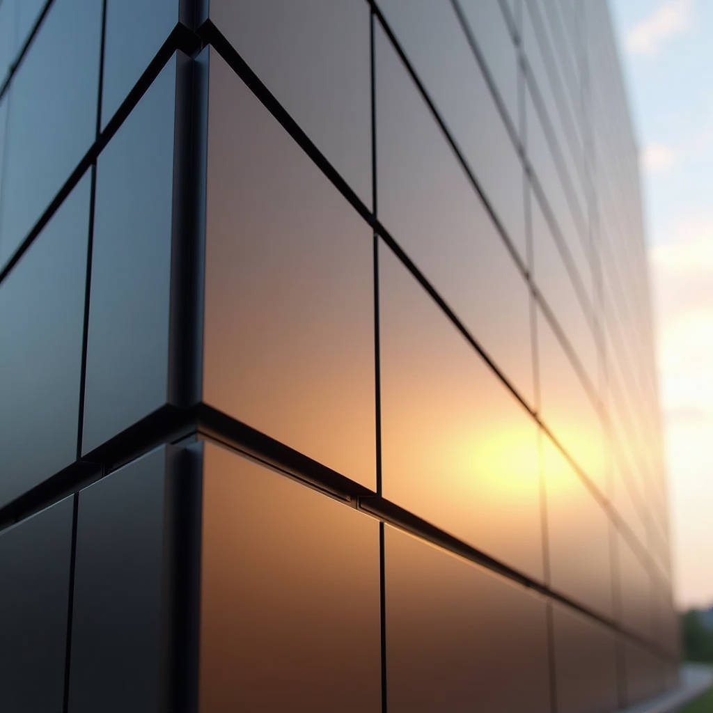
When a facade contractor asks about Clip In Aluminum Panel systems, the conversation quickly moves past generic ceiling tiles and into load-bearing exterior cladding territory. The distinction matters because solid aluminum panels engineered for clip-in attachment on vertical facades operate under fundamentally different structural demands than their interior ceiling counterparts. Wind pressure, thermal movement, and long-term weather exposure all converge on the connection points. A properly specified clip-in aluminum facade panel system distributes these forces across a concealed substructure while maintaining the clean, uninterrupted sightlines that architects specify for high-end commercial envelopes. This article examines the engineering logic behind clip-in solid aluminum cladding, the substrate and fastener requirements that prevent field failures, and the cost-performance calculus that makes these systems viable for projects ranging from airport terminals to corporate headquarters.
What Separates Clip In Aluminum Panel Facades From Interior Ceiling Systems
The term "clip-in" appears across both interior ceiling catalogs and exterior facade specifications, but the shared vocabulary hides a significant engineering gap. Interior clip-in ceiling panels typically use 0.36mm to 0.95mm thick aluminum alloy, often 1100 series, with powder-coated finishes rated for indoor humidity exposure. These panels clip onto 15/16-inch suspension grids and carry essentially zero structural load beyond their own weight. Exterior Clip In Aluminum Panel cladding systems, by contrast, start at 2.0mm solid aluminum sheet thickness and commonly reach 3.0mm for high-wind zones. The alloy shifts to 3003 or 5052 series for the strength-ductility balance required in outdoor thermal cycling. PVDF fluoropolymer coatings replace powder coatings because the 30-40 micron film thickness and Kynar 500 resin chemistry resist UV degradation, acid rain, and salt spray over decades of exposure. The clip mechanism itself differs: where ceiling clips rely on spring tension against a lightweight grid, facade clips must transfer negative wind loads from the panel face back to the substructure through engineered aluminum extrusions or stainless steel brackets.
How The Concealed Clip Mechanism Handles Wind Loads
Wind load is the dominant design driver for any exterior cladding attachment. A Clip In Aluminum Panel system on a 30-meter-tall building in a coastal exposure zone might face design wind pressures exceeding 2.5 kPa. The clip connection must resist suction forces that try to pull the panel away from the building while allowing enough movement to accommodate thermal expansion. Most clip-in facade systems use a two-part connection: an aluminum carrier rail mechanically fastened to the vertical substructure, and a panel-integrated clip profile that engages the rail with an audible snap. The geometry of this interlock determines pull-out resistance. A well-designed clip profile with a 15mm engagement depth and 3mm material thickness at the hook can typically resist 1.8-2.2 kN per linear meter of panel edge. For a 600mm by 1200mm panel, that translates to roughly 3.0-3.5 kPa of wind resistance before factoring in safety margins. Engineers should verify these values against project-specific wind tunnel data or ASCE 7-22 calculations rather than relying on catalog numbers.
Substructure Compatibility And Material Pairing
Clip-in aluminum cladding does not float in space. The substructure beneath it determines whether the system performs or fails. Three substructure types dominate the market: aluminum T-profiles, galvanized steel hat channels, and adjustable steel angle systems. Each pairing with Clip In Aluminum Panel cladding requires careful attention to galvanic corrosion potential. Aluminum-to-aluminum contact is ideal and requires no isolation. Aluminum-to-galvanized steel contact demands a separation layer, typically a 0.5mm EPDM gasket or PVC isolation tape applied to the steel face before panel installation. Stainless steel fasteners (grade 304 or 316, depending on environmental corrosivity) should connect the carrier rail to the substructure, with nylon washers under screw heads where dissimilar metals meet. The substructure spacing itself follows from panel stiffness: a 2.5mm thick solid aluminum panel with 3003-H14 temper can typically span 600mm between supports without visible oil-canning, while 3.0mm panels can extend to 800mm spans under the same deflection criteria of L/175.
Thermal Movement Accommodation In Clip-In Design
Aluminum expands at roughly 2.4mm per linear meter for every 100°C temperature change. A 3-meter-long panel on a dark-colored facade in a desert climate might see surface temperatures swing from -10°C at night to 80°C under direct sun, producing a total movement of 6.5mm. Clip-in systems must absorb this without buckling the panel face or disengaging from the carrier rail. The solution typically involves a combination of slotted clip connections and panel edge gaps. Each clip attachment point on the panel should allow at least 3mm of longitudinal slip, and panel-to-panel joints should maintain a minimum 8mm gap for movement plus sealant accommodation. Some manufacturers integrate a sliding clip design where the panel-side clip can travel within a channel on the carrier rail, effectively decoupling thermal movement from structural attachment. Specifiers should request thermal movement test data per AAMA 501.5 when evaluating clip-in systems for projects with extreme temperature ranges.
Coating Performance And Finish Durability
The visible face of a Clip In Aluminum Panel carries the architectural finish, and the coating system must survive everything the environment throws at it. PVDF coatings using 70% Kynar 500 resin content remain the benchmark for exterior aluminum cladding. The coating thickness specification matters: 30-35 microns for standard architectural applications, 40-45 microns for coastal or industrial environments. Below is a comparison of the dominant coating technologies and their relevant performance parameters for clip-in aluminum facade panels.
| Coating Type | Film Thickness | UV Resistance | Salt Spray (ASTM B117) | Color Retention (10 yr) | Relative Cost |
|---|---|---|---|---|---|
| PVDF Kynar 500 (70% resin) | 30-45 µm | Excellent | 4,000+ hours | Delta E < 5 | High |
| PVDF Kynar 500 (50% resin) | 25-35 µm | Very Good | 3,000 hours | Delta E < 8 | Medium-High |
| FEVE Fluoropolymer | 30-40 µm | Excellent | 3,500+ hours | Delta E < 5 | High |
| Super Durable Polyester | 25-35 µm | Good | 1,500 hours | Delta E < 15 | Medium |
| Standard Polyester | 20-30 µm | Moderate | 500-800 hours | Delta E > 20 | Low |
For exterior clip-in cladding applications, PVDF with 70% Kynar 500 resin is the minimum defensible specification. Projects within 5 kilometers of saltwater should additionally specify a chrome-free pretreatment and a minimum 5-micron corrosion-resistant primer layer beneath the color coat. AAMA 2605 sets the performance standard that high-quality PVDF-coated panels must meet, covering gloss retention, color change, chalk resistance, and adhesion after accelerated weathering.
Installation Sequence And Quality Control Checkpoints
Site execution separates a successful Clip In Aluminum Panel facade from one that generates punch lists. The installation sequence follows a logical order: substructure survey and adjustment, carrier rail installation with laser alignment, panel clip attachment at the bench or on-site, and panel engagement onto rails from bottom to top. Each step contains specific tolerances. Substructure flatness should not exceed 3mm deviation over a 2-meter straightedge. Carrier rail spacing must match the panel module dimension within ±1.5mm across the entire elevation. Panel clips should be fastened to the panel rear face using stainless steel blind rivets or structural adhesive tape rated for exterior shear loads, with clip spacing matching the engineering calculation rather than installer convenience. During panel engagement, the installer should hear or feel a positive lock at each clip position. A panel that slides onto the rail without resistance indicates a clip that has not engaged, which will fail under the first significant wind event. Random pull-testing of 5% of installed panels using a suction cup and spring scale can verify engagement quality before the scaffold drops.
Acoustic Integration Without Compromising Clip-In Function
Solid aluminum panels reflect sound, which creates challenges in transportation hubs, concert halls, and open-plan offices where clip-in metal cladding appears on both exterior soffits and interior feature walls. The solution lies in micro-perforation combined with acoustic backing. A Clip In Aluminum Panel with 1.5mm diameter perforations at 15% open area, backed by a non-woven acoustic fleece, can achieve a Noise Reduction Coefficient (NRC) of 0.65-0.75 when installed with a 50mm air cavity and mineral wool infill. The perforation pattern must be engineered so that structural integrity remains sufficient for the span—typically this means limiting open area to 20% maximum and maintaining a minimum 5mm unperforated border around all clip attachment points. The acoustic fleece, usually black polyester or glass fiber tissue, should be factory-applied to the panel rear face to prevent site handling damage. For exterior soffit applications, the fleece must be hydrophobic to prevent moisture retention and freeze-thaw degradation.
Cost Structure And Value Engineering Levers
Budgeting for Clip In Aluminum Panel cladding requires understanding where the money goes. Material costs break down into aluminum sheet (40-50% of panel cost), coating (15-20%), clip hardware and carrier rails (20-25%), and fabrication labor (15-20%). The aluminum sheet thickness is the single largest cost lever: moving from 2.0mm to 2.5mm adds roughly 20% to the raw material cost but can reduce substructure requirements by allowing wider support spacing. Panel size standardization is the second major lever. Custom panel sizes with multiple unique dimensions increase fabrication waste and setup time. A project that limits panel types to 4-6 standard sizes can reduce fabrication costs by 12-18% compared to one with 20-plus unique dimensions. Clip hardware costs scale with wind load requirements: a project in a 150 mph wind zone might need 40% more clips per panel than one in a 110 mph zone. Suppliers like Futeng® can provide quantity-sensitive pricing on clip extrusions when the attachment pattern is rationalized during design development. Installation labor typically runs 30-40% of the total installed cost, and the clip-in mechanism's speed advantage over face-screwed systems can recover 15-20% of that labor component on large-scale projects.
Quality Standards And Testing Protocols
Specifying Clip In Aluminum Panel systems without referencing testing standards leaves the door open for substitution with inferior products. The core standards stack includes ASTM B209 for aluminum sheet material properties, AAMA 2605 for PVDF coating performance, and ASTM E330 for structural performance under uniform static air pressure. For clip-in systems specifically, ASTM E330 testing should simulate both positive and negative pressure cycles, with deflection measured at panel center and residual deformation checked after load removal. AAMA 501.1 covers dynamic water penetration testing, which is critical for clip-in joints that rely on gaskets rather than wet seals. For projects in seismic zones, AAMA 501.4 provides a protocol for evaluating cladding performance under inter-story drift conditions. The clip connection itself should be tested to failure in pull-out, with the failure mode documented: a ductile failure where the clip deforms before releasing is preferable to a brittle failure where the clip snaps suddenly. Test reports should be project-specific rather than generic catalog data, and the testing laboratory should hold ISO/IEC 17025 accreditation.
Common Failure Modes And Prevention Strategies
Field experience with Clip In Aluminum Panel facades reveals several recurring failure patterns that good specification and inspection can prevent. Oil-canning, the visible waviness across the panel face, results from residual stresses in the aluminum sheet combined with inadequate panel thickness for the support spacing. Prevention requires specifying a minimum thickness-to-span ratio of 1:250 and requesting that the fabricator use stress-relieved sheet stock. Clip disengagement under wind suction typically traces back to insufficient engagement depth or installation error. Specifying a minimum 12mm clip engagement and requiring third-party pull testing on 5% of panels addresses this. Galvanic corrosion at clip-to-substructure interfaces appears within 2-3 years when isolation materials are omitted. The fix is simple: EPDM or PVC isolation at every dissimilar metal contact point, documented in the shop drawing review. Coating delamination at panel edges often results from inadequate edge coverage during the coating process. The specification should require a minimum 15mm coating return onto the panel rear face at all edges. Finally, acoustic vibration in high-wind conditions can occur when large unperforated panels lack sufficient stiffening. Adding a bead of structural silicone between the panel rear face and the carrier rail at mid-span can dampen vibration without constraining thermal movement.
Sourcing Considerations For International Projects
Procurement teams managing international construction projects face specific challenges when sourcing Clip In Aluminum Panel systems. Lead times for custom-fabricated panels typically range from 6-10 weeks from approved shop drawings, with PVDF coating adding 2-3 weeks to the schedule. Ocean freight from Asian manufacturing hubs to North American or European ports adds 4-6 weeks, making total procurement timelines of 14-18 weeks realistic for most projects. Documentation requirements should include mill test certificates for the aluminum coil confirming alloy and temper, PVDF coating batch certificates showing resin content and film thickness, and factory production sample panels for onsite mockup approval before full production begins. Packaging specification matters: panels should ship with interleaving polyethylene film between faces, edge protectors on all four sides, and crating that prevents panel movement during transit. A 2% overage allowance for site damage and future replacement panels is standard practice. For projects requiring LEED or BREEAM certification, the aluminum should contain a minimum 30% recycled content, and the coating facility should provide VOC emissions documentation. Suppliers with ISO 9001 and ISO 14001 certifications simplify the compliance documentation chain for the main contractor.
Designing For Disassembly And End-Of-Life
The clip-in attachment method carries an underappreciated advantage for sustainable building design: it enables non-destructive disassembly. Unlike face-screwed or adhesive-fixed cladding, a Clip In Aluminum Panel system can be removed panel by panel using a suction cup lifter and a release tool that disengages the clip mechanism from the carrier rail. This matters for two reasons. First, individual damaged panels can be replaced without disturbing adjacent panels, reducing maintenance costs and material waste over the building's service life. Second, at end-of-life demolition, the aluminum panels can be fully recovered for recycling. Aluminum recycling requires only 5% of the energy needed for primary aluminum production, and the PVDF coating burns off cleanly in the remelt process without producing toxic byproducts. Specifying mechanical clip connections rather than adhesive bonds means the entire cladding system can be separated into single-material streams: aluminum panels, aluminum or steel carrier rails, and stainless steel fasteners. A design-for-disassembly approach aligns with the ISO 20887 standard for adaptability and disassembly in buildings, and it contributes credits under LEED v4.1's Building Life-Cycle Impact Reduction category.
The engineering reality of clip-in aluminum cladding is that success lives in the details: the engagement depth of the clip profile, the isolation material at dissimilar metal junctions, the coating thickness at panel edges, and the substructure tolerance on the day of installation. When these details are specified clearly and verified systematically, the result is a facade system that delivers the architectural intent of seamless, monolithic metal surfaces while performing reliably under wind, weather, and time. The clip-in mechanism itself is not a commodity feature. It is a structural connection that deserves the same engineering attention as any other load path in the building envelope. For project teams evaluating these systems, the priority should be to review clip connection test data, verify thermal movement accommodation, and confirm that the coating specification matches the environmental exposure. Getting those three elements right eliminates most of the problems that generate change orders and warranty claims downstream.